Table of Contents
Advertisement
Quick Links
Advertisement
Table of Contents

Related Manuals for Art Pro Channel


Summary of Contents for Art Pro Channel
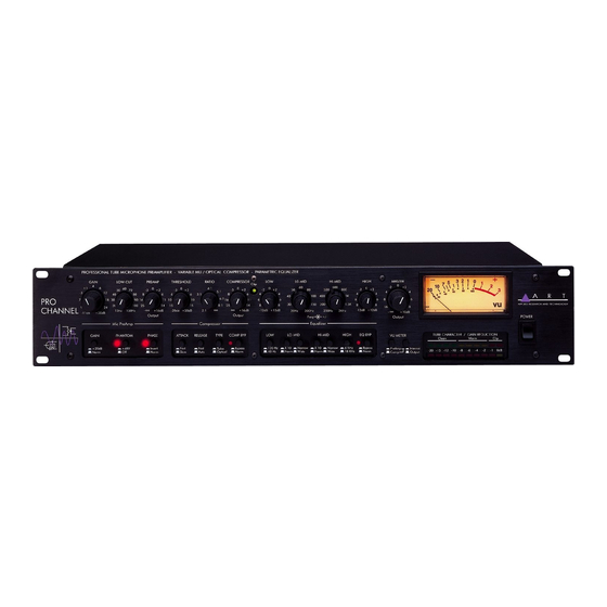
- Page 1 APPLIED RESEARCH & TECHNOLOGY, Inc. 215 TREMONT STREET ROCHESTER, NEW YORK 14608 USA (716) 436-2720 – Voice (716) 436-3942 – Fax Internet http://www.artroch.com E-mail: art@art.com Pro Channel Professional Tube Mic Preamp, Compressor & Equalizer 215-5004-100...
- Page 2 Pro Channel PROFESSIONAL TUBE MIC PREAMP, COMPRESSOR & EQUALIZER USER’S GUIDE...
-
Page 3: Table Of Contents
Contents FEATURES................. 4 OVERVIEW ................ 5 ? ........5 HY USE AN EXTERNAL PROCESSING CHANNEL ..................5 ESIGN OTES SETTING UP ..............6 ..................6 NPACKING AC P ................6 OWER OOKUP ................6 UDIO ONNECTIONS ..................6 NSTALLATION .................7 AFETY RECAUTIONS ..................7 OWERING FRONT PANEL CONTROLS & INDICATORS...... 7 .................7 REAMP IRCUIT... - Page 4 What is the best way to use EQ?..............18 ................19 PECIAL FFECTS ..................19 ROUNDING TUBE REPLACEMENT............19 BLOCK DIAGRAM.............20 A R T PRO CHANNEL SPECIFICATIONS......21 WE’RE ON-LINE!...............22 WARRANTY AND SERVICE INFORMATION .....22 ................22 IMITED ARRANTY .................... 23 ERVICE...
-
Page 5: Features
– all in one unit. Developed in partnership with studio and live sound engineers, the Pro Channel possesses a “sound” that is not available from any other product on the market – at any price! The Pro Channel was designed and constructed with the best components, assuring a lifetime of quiet, reliable performance. -
Page 6: Overview
“big” consoles use external EQs, compressors and preamps! The goal of any recording is to get the sounds right before you commit them to tape. The Pro Channel exists to help you get it right so you don’t have to “fix it in the mix.” Design Notes The Pro Channel is a multi-purpose tool for audio engineering and recording. -
Page 7: Setting Up
Pro Channel. Audio Connections Audio connections to and from the Pro Channel are balanced XLR (Pin 2 = Hot (+), Pin 3 = Cold (-), Pin 1 = Ground) and unbalanced ¼” (Tip = Hot (+), Sleeve = Ground). -
Page 8: Safety Precautions
Pro Channel on before any monitoring levels or power amps are turned on. The Pro Channel has the ability to add over 80dB of gain to its input signal. This can cause the Pro Channel to produce a “thump” on power up and power down. -
Page 9: Gain Switch
Array (under the VU meter) for a visual reference to the Pro Channel’s internal signal levels. Hint: the “sweet spot” for the Pro Channel is when all 4 of the yellow “warm” LEDs in the Tube Character Array are lit. -
Page 10: Tube Drive/Gain Reduction Display
6dB before audible distortion occurs. If this light flickers, don’t panic. The unique design of the Pro Channel allows the tube to distort well before any other gain stage. When a tube goes into distortion, it is a gradual process and tends to sound pleasing for a range before it turns into a distortion box. -
Page 11: Compressor Circuit
Compressor Circuit Threshold Control The Threshold control sets the point at which the compressor circuit will act on the input signal. Turning this control counterclockwise lowers the Threshold (adding more compression to a signal). Turning this control clockwise raises the threshold. Setting the Threshold control is dependent on the Preamp Output control (or the output of the device plugged into the compressor return insert... -
Page 12: Type Switch
Type Switch This switch covers one of the more unique features of the Pro Channel. In the “out” position (Optical), the Pro Channel’s compressor employs the award-winning Vactrol®- based compression element from our Pro VLA. Switching to the “in” position engages the dual-triode variable-mu control element. -
Page 13: Clip Indicator
Turn down either the Preamp Output control, the Compressor Output control, or the output level of the device plugged into the compressor return insert point. Equalizer Circuit The equalizer circuit in the Pro Channel is a tube-based, semi-parametric, four-band equalizer. All of the bands overlap, giving you the ultimate in flexibility. -
Page 14: Lo-Mid Shift X 10 Switch
Lo-Mid Shift x 10 Switch The Lo-Mid Shift x 10 switch determines the range over which the Lo-Mid frequency control will cover. In its “out” position, the range is set at 20Hz to 200Hz. In its “in” position the range is set at 200Hz to 2KHz. Note: You’ll notice the Low Frequency and Lo-Mid Frequency controls overlap (meaning they cover the same frequencies). -
Page 15: High Shift Switch
Master Controls Master Output Level Control The Master Output control sets the final output level leaving the Pro Channel. When the control is fully counterclockwise, there is no output. Turning the control clockwise increases the level of the output to a maximum of +10dB of gain. When setting the Output Level control, refer to the VU Meter (set for the “Output”... -
Page 16: Vu Meter
A backlit, average reading VU meter is provided to accurately monitor levels at several points in the Pro Channel. The “0VU” level is calibrated to +4dBu at any of the internal points, or at the ¼” Output connector. For the same calibration on the XLR output, a 600Ω... -
Page 17: Input
This jack may be used to connect the output of a piece of equipment to the input of the compressor circuit in the Pro Channel. Since there is no input level control to the compressor in the Pro Channel, the piece of equipment patched into the insert loop should have an output level control. -
Page 18: Loop Connections
To use only the compressor circuit of the Pro Channel: Plug a line level signal (or a send from a mixer) into the Compressor Return Jack. Connect the Compressor Send jack to the input of the next piece of equipment (or the return of a mixer). -
Page 19: Eq Tips
EQ Tips What is the best way to use EQ? There are two schools of thought on EQ: 1) Use as much as you need to make things sound good. 2) Don’t use any EQ. Most people follow the suggestion of “if it sounds good, it is good.” You need to use your ears and judge for yourself as their are no steadfast rules for EQ’ing. -
Page 20: Special Effects
Placing signals purposely out of phase can also yield interesting results. No harm will come to the Pro Channel with this type of experimentation. However, be sure to have output and monitoring levels turned DOWN before “testing”... -
Page 21: Block Diagram
Block Diagram - 20 -... -
Page 22: A R T Pro Channel Specifications
A R T Pro Channel Specifications Dimensions 6.5"D x 19"W x 3.50"H Weight 12.0 lbs Maximum Gain XLR to XLR 83dB ¼” to ¼” 65dB Dynamic Range >100dB (20-20KHz) Frequency Response 20Hz to 20KHz (±0.5dB) Low-Cut Filter Single-Pole Variable -3dB@10Hz to 250Hz Input / Output Connections XLR balanced &... -
Page 23: We're On-Line
We’re on-line! For Product information, questions, applications, tips, answers and general discussion with A R T employees look for A R T on the Internet. Email us at art@artroch.com Check out our Web Site at: http://www.artroch.com Warranty and Service Information Limited Warranty Applied Research and Technology, Inc. -
Page 24: Service
Service The following information is provided in the unlikely event that your unit requires service. Use this procedure to return units in the United States only. For service outside the United States, please contact your authorized A R T distributor. 1) Be sure the unit is the cause of the problem.
Need help?
Do you have a question about the Pro Channel and is the answer not in the manual?
Questions and answers