Table of Contents
Advertisement
Quick Links
TABLE OF CONTENTS
Introduction ......................................................................................... 2
Installation ........................................................................................... 3
AC Power Hookup ............................................................................. 3
Audio Connections ............................................................................ 3
Safety Precautions ............................................................................ 3
Controls and Indicators ....................................................................... 4
Input Gain Control ............................................................................. 4
Sample Rate Switch .......................................................................... 4
Sample Rate LED Indicators ............................................................. 5
Signal Level LED Indicators ............................................................... 5
Tube Warmth Control ........................................................................ 6
Power LED Indicator ......................................................................... 6
Connections ........................................................................................ 7
¼" Input Jacks.................................................................................... 8
¼" Output Jacks ................................................................................ 8
S/PDIF Output Jack ........................................................................... 8
S/PDIF Input Jack ............................................................................. 8
Power Jack ....................................................................................... 9
Operation ........................................................................................... 10
Warranty Information ........................................................................ 14
Service ............................................................................................... 15
DI/O Specifications ............................................................................ 16
The ART
DI/O
- 1 -
Advertisement
Table of Contents

Related Manuals for Art DIO Preamp System II


Summary of Contents for Art DIO Preamp System II
-
Page 1: Table Of Contents
¼” Input Jacks... 8 ¼” Output Jacks ... 8 S/PDIF Output Jack ... 8 S/PDIF Input Jack ... 8 Power Jack ... 9 Operation ... 10 Warranty Information ... 14 Service ... 15 DI/O Specifications ... 16 The ART DI/O - 1 -... -
Page 2: Introduction
You can loop thru the DI/O to add “analog” warmth and musicality to an existing digital track. The latest refinements in ART’s award winning tube pre-amp design are integrated on the front end, before the A/D converter, for analog gain and dynamic range control. -
Page 3: Installation
States of America have been modified to comply with the required electrical specifications. Only use the adapter that came with the DI/O. If the adapter becomes lost or damaged; contact ART Customer Service for replacement. If you need to purchase one locally, just make sure that you specify 9 Volt AC output (not DC), at 800 ma. -
Page 4: Controls And Indicators
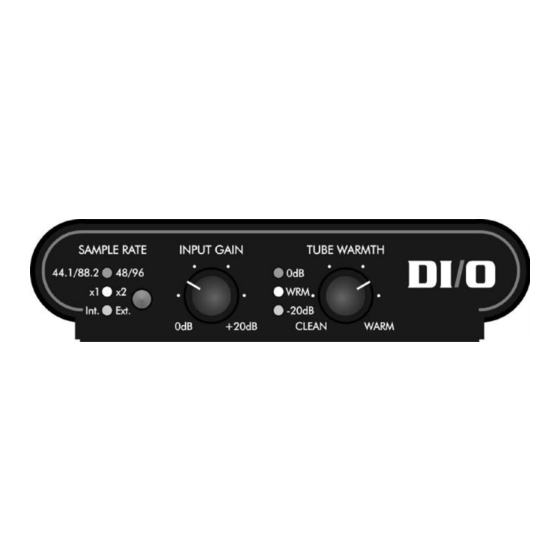
CONTROLS & INDICATORS INPUT GAIN CONTROL The Input Gain control allows you to add gain to the input signal before the tube and A/D converter. Turn the control clockwise to increase gain and counterclockwise to decrease gain. At the fully counterclockwise position (0dB), incoming signals are passed at unity gain to the A/D converter. -
Page 5: Sample Rate Led Indicators
SAMPLE RATE LED INDICATORS The Sample Rate LED Indicators show the current sample rate that the DI/O’s A/D and D/A are operating at. When set to one of the internally generated sample rates (44.1, 48, 88.2, or 96kHz), the DI/O provides the Master clock source from its internal crystal clock. -
Page 6: Tube Warmth Control
TUBE WARMTH CONTROL This control allows you to vary the tube circuits warmth contribution to the audio signal chain. At the Clean end, there is essentially no tube processing and the yellow Warm LED should not light. As you turn up the control, the drive to the tube is increased while its output is adjusted, to maintain a fairly constant output signal to the A/D. -
Page 7: Connections
CONNECTIONS variety of equipment. All inputs and outputs are located on the rear panel. Standard ¼” audio inputs and outputs make patching simple. - 7 -... -
Page 8: ¼" Input Jacks
¼” INPUT JACKS The ¼” Input jacks are for instrument and line level signals. They have a high input impedance to minimize any loading effects on instrument pickups. They can also handle up to +20 dBu signals for line level signal sources. -
Page 9: Power Jack
DI/O. If the adapter ever becomes damaged, immediately discontinue use. They can be purchased locally or directly from ART. Just make sure that you specify 9 Volt AC output (not DC), at 800 ma. Fill in the following information for your reference:... -
Page 10: Operation
OPERATION The main function of the DI/O is to provide a high-quality alternative to the digital audio converters of your computer’s soundcard. Simply plug the analog output from your instrument, mixer, or preamp into the DI/O’s 1/4” Inputs and connect the DI/O’s S/PDIF Output to your soundcard. -
Page 11: Other Applications
The DI/O contains tube circuitry that can be used to warm-up digital recordings. The amount of tube warmth is increased by turning the DI/O’s Tube Warmth knob clockwise. This control lets you increase the amount of tube drive without increasing the DI/O’s output level. You can add warmth to any sound without having to readjust the levels going through the DI/O. -
Page 12: Special Effects
USING BOTH ANALOG INS AND OUTS The DI/O also can be used on completely analog signal paths. For example, during a live performance, the DI/O can sweeten up the harsh sound of some keyboards and synthesizers. Simply use the 1/4” Input and Output jacks to insert the DI/O between your keyboards and amplifiers. - Page 13 They may sound better, they may sound worse. The choice is yours. Please realize that unauthorized alterations to the DI/O will result in voiding the warranty. For more application ideas, information, and suggestions on complementary equipment that can be used with the DI/O, visit our website at: http://www.artproaudio.com - 13 -...
-
Page 14: Warranty Information
WARRANTY INFORMATION Limited Warranty Applied Research and Technology will provide warranty and service for this unit in accordance with the following warrants: Applied Research and Technology, (A R T) warrants to the original purchaser that this product and the components thereof will be free from defects in workmanship and materials for a period of three years from the date of purchase. -
Page 15: Service
SERVICE The following information is provided in the unlikely event that your unit requires service. 1) Be sure that the unit is the cause of the problem. Check to make sure the unit has power supplied, all cables are connected correctly, and the cables themselves are in working condition. -
Page 16: Di/O Specifications
Output Impedance Tube Type Power Requirements ART maintains a policy of constant product improvement. ART reserves the right to make changes in design or make additions to or improvements upon this product without any obligation to install same on products previously manufactured.
Need help?
Do you have a question about the DIO Preamp System II and is the answer not in the manual?
Questions and answers