Advertisement
Quick Links
AKG.WIRELESS
Bedienungshinweise . . . . . . . . . . . . . . . . . . . S. 2
Bitte vor Inbetriebnahme des Gerätes lesen!
User Instructions . . . . . . . . . . . . . . . . . . . . . p. 10
Please read the manual before using the equipment!
Mode d'emploi . . . . . . . . . . . . . . . . . . . . . . . p. 19
Veuillez lire cette notice avant d'utiliser le système!
Istruzioni per l'uso . . . . . . . . . . . . . . . . . . . . p. 27
Prima di utilizzare l'apparecchio, leggere il manuale!
Modo de empleo . . . . . . . . . . . . . . . . . . . . . p. 35
Antes de utilizar el equipo, sírvase leer el manual!
PR40
Instruções de uso . . . . . . . . . . . . . . . . . . . . p. 43
Favor leia este manual antes de usar o equipamento!
WMS40
microtools
portablereceiver
WIRELESS
MICROPHONE
SYSTEM
P
Advertisement

Related Manuals for AKG PR 40


Summary of Contents for AKG PR 40
- Page 1 AKG.WIRELESS WIRELESS MICROPHONE SYSTEM WMS40 microtools Bedienungshinweise ....S. 2 Bitte vor Inbetriebnahme des Gerätes lesen! User Instructions ..... p. 10 Please read the manual before using the equipment! Mode d’emploi .
-
Page 2: Fcc Statement
FCC Statement • This equipment has been tested and • found to comply with the limits for a Class B digital device, pursuant to Parts 74, 15, and 90 of the FCC Rules. These limits are • designed to provide reasonable protec- tion against harmful interference in a resi- dential installation. - Page 3 Shielded cables and I/O cords must be used for this equipment to comply with the relevant FCC regulations. Changes or modifications not expressly approved in writing by AKG Acoustics may void the user’s authority to operate this equipment. This device complies with Part 15 of the FCC Rules.
-
Page 4: Safety And Environment
1 Safety and Environment 1.1 Safety 1. Do not expose the equipment to direct sunlight, excessive dust, moi- sture, rain, mechanical vibrations, or shock. 1.2 Environment 1. The AC adapter will draw a small amount of current even when the equipment is switched off. - Page 5 2 Description 2.1 Introduction Thank you for purchasing an AKG product. This Manual contains important instructions for setting up and operating your equipment. Please take a few minutes to read the instructions below carefully before operating the equipment. Please keep the Manual for future reference.
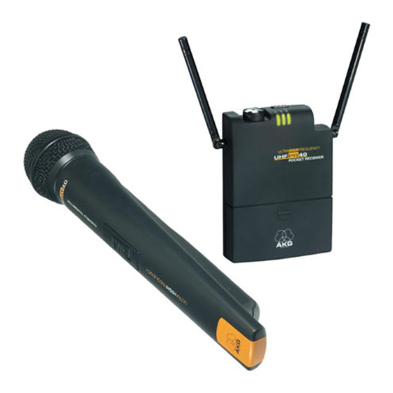
- Page 6 • CU 40 charger rela • Custom versions of AKG headphones with .1-in. jack plug. (On request – K 10 shown.) 2.4 Description The PR 40 is a portable diversity receiver for use with all AKG WMS 40 Series freq...
- Page 7 ENG use. Thanks to its compact dimensions and convenient belt clip, the PR 40 is an excellent receiver for tour guide and small interpretation systems. A preset squelch will mute the receiver if...
- Page 8 Fig. 1: Top panel controls.
- Page 9 2.5 Controls 2.5.1 Top Panel (Fig. 1) ON/OFF: On/off switch. Output jack: This .1-in. TRS jack on the receiver top panel provides a fixed-level line output and an adjusta- ble mono headphone output. The volume control (3) lets you adjust the volume level of the headphone out- put.
- Page 10 Volume control: Sets the volume level of the headphone output (2). The color of the volume control knob indicates the receiving frequency of your receiver. RF LED: Indicates the field strength of the received signal: LED lighting green: optimum field strength.
- Page 11 LED lights red: batteries will be dead in about 60 minutes. Antennas: Being a diversity receiver, the PR 40 uses two antennas to receive the transmitter signals at two different spots. The diversity circuit will automatically activate the anten- na that provides the better signal.
- Page 12 µ ¸ ver, cuit µ ¸ Fig. 2: Bottom and rear panels.
- Page 13 2.5.2 Rear Panel (Fig. 2) Type plate with approval marks and frequency information (frequencies, frequency sets, color code). µ Belt clip for fixing the receiver on your belt. 2.5.3 Bottom Panel (Fig. 2) ¸ Charging contacts for charging rechargeable batteries inside the bat- tery compartment using the optional CU 40 charger.
- Page 14 3 Setting Up 3.1 Powering To power the PR 40 portable receiver you can use the supplied 1.5 V AAA size dry batteries or 1.5 V AAA size rechargeable batteries (not supplied). 3.2 Inserting/Replacing and Testing Batteries (Fig. 3) 1. Depress the snap hook on the battery compartment lid (1).
- Page 15 Fig. 3: Inserting batteries.
- Page 16 3. If there are dead or defective batte- ries inside the battery compartment, remove the batteries. 4. Insert the supplied or new batteries (2) into the battery compartment as shown in fig. 3. 5. Set the ON/ OFF switch (3) to ON. If the batteries are in good condition, the BATT LED (4) will light green.
- Page 17 3.3 Using Rechargeable Batteries (Fig. 4) Fig. 4: Using the optional CU 40 charger. Instead of dry batteries, you can also use two 1.5 V rechargeable batteries to power the receiver. We recommend SANYO HR-4U (650 mAh) or Panasonic Rechargeable PRO+ (550 mAh) NiMH rechargeable batteries.
- Page 18 er (1) into the optional CU 40 charger (2) as shown in fig. 4. Important: Before placing the receiver in the charger, switch the receiver OFF and fold the antennas all the way down, against the side panels of the receiver. With the antennas folded down, it will be easier to center the receiver inside the char- ging compartment and the charger...
- Page 19 4 Applications 4.1 Mounting the Receiver on a Mixer, Pedalboard, or Video Camera 1. Press the ends of the belt clip inward as shown in fig. 5 and remove the belt clip. 2. Cut two 2-inch lengths off the sup- plied Velcro strip.
- Page 20 strips and attach it to the receiver rear panel. 4. Remove the backing from the other strip and attach it to the mixer, pedal- board, or camera. Fig. 6: Optimum antenna position. To ensure perfect reception, position the Velcro strip so that the antennas on the receiver will protrude above the mixer, pedalboard, or camera.
- Page 21 4.1.1 Audio Connection (Fig. 7) The supplied connecting cable lets you connect the line output on the receiver dal- to an audio input on a mixing console, pedalboard, or video camera. 1. Check what connector type you will need for your equipment and solder the connector to the cable.
- Page 22 ole, will Fig. 7: Audio connection power OFF. Refer to the manual of your equip- ment. 3. Plug the .1-in. jack plug (1) on the connecting cable into the output jack (2) on the receiver.
- Page 23 AKG headphones in a custom version with a 0.1-in. TRS jack plug. Important: Do not connect head- phones with an impedance of less than 16 Ω to the PR 40 receiver. Headphones with a lower im- pedance would overload...
- Page 24 cei- Fig. 8: connecting headphones. s in 1. To relieve the connection of the strain of the headphone cable, pass the headphone cable under the belt clip If y as shown in fig. 8 (left). 2. Plug the .1-in. jack plug (1) on the ver.
- Page 25 4.3 Aligning the Antennas (Fig. 9) For optimum recep- tion, point each antenna away from the receiver at an angle of 45 de- grees. With antennas aligned like this, the diversi- function will operate optimally Fig. 9: Optimum and prevent dis- antenna alignment turbances such as noise or dropouts most efficiently.
- Page 26 protrude above the equipment case. This will prevent dropouts due to shadow effects of the case. 5 Cleaning To clean the transmitter case, use a soft cloth moistened with water.
- Page 27 6 Specifications Receiving frequency range: 710 to 865 MHz Modulation: Audio bandwidth: 40 to 20,000 Hz T.H.D.: <0.8% Signal/noise ratio: 108 dB(A) typ. with Current consumption: 120 mA typ. Battery life: >6 hours (2 x 1.5 V AAA size batteries) Audio outputs: Unbal.
- Page 28 Ci riserviamo il diritto di effettuare modifiche tecniche. Nos reservamos el derecho de introducir modificaciones técnicas. Especificações sujeitas à mudanças sem aviso prévio. AKG Acoustics GmbH Lemböckgasse 21–25, P.O.B. 158, A-1230 Vienna/AUSTRIA, Tel: (+43 1) 86 654-0*, Fax: (+43 1) 86 654-7516, www.akg.com, e-mail: sales@akg.com, Hotline: (+43 676) 83200 888, hotline@akg.com AKG Acoustics GmbH Bodenseestraße 228, D-81243 München/GERMANY, Tel: (+49 89) 87 16-0, Fax: (+49 89) 87 16-200, www.akg.com/de, e-mail: infode@akg.com,...
Need help?
Do you have a question about the PR 40 and is the answer not in the manual?
Questions and answers