Table of Contents
Advertisement
Quick Links
Advertisement
Table of Contents

Subscribe to Our Youtube Channel
Related Manuals for Neousys Technology PCIe-PoE354at

Summary of Contents for Neousys Technology PCIe-PoE354at
- Page 1 PCIe-PoE354at/PCIe-PoE352at User’s Manual Neousys Technology Inc. PCIe-PoE354at/PCIe-PoE352at 4-Port / 2-Port Server-grade Gigabit 802.3at PoE+ Frame Grabber Card User’s Manual Rev. A1 Published Jun 18th, 2015 Copyright © 2015 Neousys Technology Inc. All Right Reserved. Page 1 of 31...
- Page 2 PCIe-PoE354at/PCIe-PoE352at User’s Manual Date Description Version 2015/06/18 First formal release Copyright © 2015 Neousys Technology Inc. All Right Reserved. Page 2 of 31...
-
Page 3: Table Of Contents
2.3 PCIe-PoE352at Top View....................... 8 Chapter 3 Getting Start...........................9 3.1 Configure Board ID of PCIe-PoE354at/352at..............9 3.2 Configure 12 VDC Source (PCIe-PoE354at Only)............11 3.3 Install the PCIe-PoE352at....................12 3.4 Install the PCIe-PoE354at Frame Grabber Card............14 3.5 Connect a PoE or Non-PoE Device...................16 Chapter 4 Driver Installation and Settings.................. -
Page 4: Declaimer
Company/product names mentioned herein are used for identification purposes only and are trademarks and/or registered trademarks of their respective companies. Copyright © 2015 Neousys Technology Inc. All Right Reserved. Page 4 of 31... -
Page 5: Chapter 1 Introduction
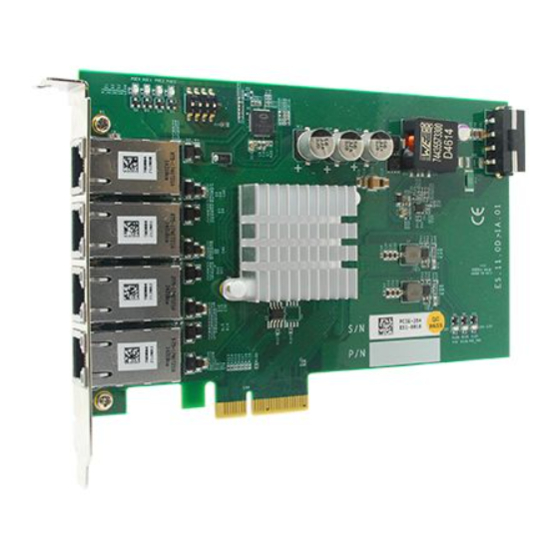
PCIe-PoE354at/PCIe-PoE352at User’s Manual Chapter 1 Introduction 1.1 Overview PCIe-PoE354at is world’s first PoE frame grabber card combing server-grade GigE controller and 802.3at PoE+ capability. Inheriting Neousys’ expertise in PoE technology, PCIe-PoE354at further implements the updated 802.3at-2009 standard and offers up to 25.5W of power each port. -
Page 6: Product Specification
0°C ~ 55°C with air flow Dimension 167.7 mm (W) x 111.2 mm (H) * PCIe-PoE354at is designed to obtain 12 VDC for PoE devices from either PCI Express bus or on-board 4-pin power connector according to a user-configurable jumper. 1.2.2 Specification of PCIe-PoE352at... -
Page 7: Chapter 2 Know Your Pcie-Poe354At/352At
Know your PCIe-PoE354at/352at 2.1 Unpacking your PCIe-PoE354at/352at When you receive the package of PCIe-PoE354at/352at, please check immediately if the package contains all the items listed in the following table. If any item is missing or damaged, please contact your local dealer or Neousys Technology Inc. for further assistance. -
Page 8: Pcie-Poe352At Top View
PCIe-PoE354at/PCIe-PoE352at User’s Manual 2.3 PCIe-PoE352at Top View Copyright © 2015 Neousys Technology Inc. All Right Reserved. Page 8 of 31... -
Page 9: Chapter 3 Getting Start
PCIe-PoE354at/352at incorporates a DIP switch to configure user-defined board ID. The board ID can be used as a parameter in API to specify the PCIe-PoE354at/352at card. The DIP switch is located on the upper-left corner of PCB. P1 ~ P3 of DIP switch are used to specify the board ID. - Page 10 PCIe-PoE354at/PCIe-PoE352at User’s Manual Copyright © 2015 Neousys Technology Inc. All Right Reserved. Page 10 of 31...
-
Page 11: Configure 12 Vdc Source (Pcie-Poe354At Only)
PCIe-PoE354at/PCIe-PoE352at User’s Manual Configure 12 VDC Source (PCIe-PoE354at Only) PCIe-PoE354at/352at requires 12 VDC power for its PoE+ PSE function. By default, both PCIe-PoE354at and PCIe-PoE352at obtain 12 VDC directly from the PCI Express connector so no external power plug is needed. -
Page 12: Install The Pcie-Poe352At
Align and insert the golden-finger connector of PCIe-PoE352at into the PCI Express slot until it’s firmly contacted. Fix the PCIe-PoE352at to the host computer using with a screw. Copyright © 2015 Neousys Technology Inc. All Right Reserved. Page 12 of 31... - Page 13 PCIe-PoE354at/PCIe-PoE352at User’s Manual Copyright © 2015 Neousys Technology Inc. All Right Reserved. Page 13 of 31...
-
Page 14: Install The Pcie-Poe354At Frame Grabber Card
Most modern computers have x16 PCI Express slot(s) for installing a graphics card. It can be possibly configured as a PCI Express Root Port for installing a general PCI Express card. Please contact the vendor of your computer to check if PCIe-PoE354at can be fitted into your x16 PCI Express slot. - Page 15 PCIe-PoE354at/PCIe-PoE352at User’s Manual If the PCIe-PoE354at is configured to obtain 12 VDC from 4-pin power connector, plug in the 4-pin power plug from your ATX power supply and make sure they are firmly contacted. Note When configuring PCIe-PoE354at to obtain 12 VDC from 4-pin power connector. For most Copyright ©...
-
Page 16: Connect A Poe Or Non-Poe Device
PCIe-PoE354at and PCI-PoE352at can work with both PoE Powered Devices (PD) and regular Ethernet devices. A CAT5 or CAT6 cable is usually used for PoE applications. Since PCIe-PoE354at and PCIe-PoE352at are designed for Gigabit Ethernet connectivity, a CAT-6 cable is highly recommended. -
Page 17: Chapter 4 Driver Installation And Settings
Neousys provides a very convenient utility in “Drivers & Utilities DVD” to allow the “One-Click” driver installation. This utility automatically detects your Windows operating system and installs corresponding driver for your PCIe-PoE354at/352at with just one mouse click. 4.1.1 Install Driver Using “One-Click” Driver Installation Insert the “Drivers &... -
Page 18: Install Driver Manually
PCIe-PoE354at/PCIe-PoE352at User’s Manual 4.1.2 Install Driver Manually You can also manually install the driver for PCIe-PoE354at/352at. Please refer to the following information about installing the driver for different operating system. Windows XP Execute x:\Driver_Pool\GbE_I350\XP\APPS\PROSETDX\XP2K3_32\DxSetup.exe , where x: denotes the volume of your DVD drive Windows 7 or Windows 8/8.1 32-bit... -
Page 19: Driver Settings
PCIe-PoE354at/PCIe-PoE352at User’s Manual 4.2 Driver Settings PCIe-PoE354at and PCIe-352at offer the Gigabit Ethernet connectivity via Intel® I350 GbE controller. When connecting to a high-speed PoE device, such as a GigE camera, you can adjust some driver settings to have better transmission throughput and connection stability. - Page 20 Click Configure button and a property dialog appears. Click on the Advanced tab. Select the Jumbo Packet settings, and select the expected jumbo frame size. (for connecting a Ethernet device with high data rate, 9014 Bytes is suggested) Copyright © 2015 Neousys Technology Inc. All Right Reserved. Page 20 of 31...
-
Page 21: Receive Buffer
(maximal 2048 bytes) for better performance. You can change the settings of receive buffer by following the steps listed below. Open the Network Connections and double-click on a corresponding Local Area Connection. Copyright © 2015 Neousys Technology Inc. All Right Reserved. Page 21 of 31... - Page 22 PCIe-PoE354at/PCIe-PoE352at User’s Manual Click Configure button and a property dialog appears. Click on the Advanced tab. Select the Performance Options settings and click the Properties button. Copyright © 2015 Neousys Technology Inc. All Right Reserved. Page 22 of 31...
- Page 23 PCIe-PoE354at/PCIe-PoE352at User’s Manual Adjust the value of Receive Buffers. (for connecting a Ethernet device with high data rate, 2048 Bytes is suggested) Copyright © 2015 Neousys Technology Inc. All Right Reserved. Page 23 of 31...
-
Page 24: Transmit Buffers
You can change the settings of transmit buffer by following the steps listed below. Open the Network Connections and double-click on a corresponding Local Area Connection. Copyright © 2015 Neousys Technology Inc. All Right Reserved. Page 24 of 31... - Page 25 PCIe-PoE354at/PCIe-PoE352at User’s Manual Click Configure button and a property dialog appears. Click on the Advanced tab. Select the Performance Options settings and click the Properties button. Copyright © 2015 Neousys Technology Inc. All Right Reserved. Page 25 of 31...
- Page 26 PCIe-PoE354at/PCIe-PoE352at User’s Manual Adjust the value of Transmit Buffers. Copyright © 2015 Neousys Technology Inc. All Right Reserved. Page 26 of 31...
-
Page 27: Appendix A Using Per-Port Poe On/Off Control
Click “Next >” and specify the directory of installing related files. The default directory is C:\Neousys\WDT_DIO. Once the installation is finished, a dialog appears to prompt you to reboot the system. Copyright © 2015 Neousys Technology Inc. All Right Reserved. Page 27 of 31... - Page 28 \Sample\IVIS_DTIO_Demo (iVIS-200 DTIO Demo) * \Sample\POE_Demo (PoE per-port Control Demo) \Sample\PWM_Demo (PWM Control Demo) * \Sample\WDT_Demo (Watchdog Demo) * * These sample programs can not work with PCIe-354at/352at Copyright © 2015 Neousys Technology Inc. All Right Reserved. Page 28 of 31...
-
Page 29: Per-Port On/Off Control Function Reference
Get the current power on/off status of designated PoE port. Parameter boardId DWORD value (0 ~ 7) to indicate board ID of selected PCIe-PoE354at/352at card. Please refer to section 3.1 for configuring board ID for your PCIe-PoE354at/352at. port DOWRD value (1 ~ 4) to specify the PoE port. -
Page 30: Pci_Enablepoeport
Enable (turn on) PoE power for designated PoE port. Parameter boardId DWORD value (0 ~ 7) to indicate board ID of selected PCIe-PoE354at/352at card. Please refer to section 3.1 for configuring board ID for your PCIe-PoE354at/352at. port DOWRD value (1 ~ 4) to specify the PoE port. - Page 31 Disable (turn off) PoE power for designated PoE port. Parameter boardId DWORD value (0 ~ 7) to indicate board ID of selected PCIe-PoE354at/352at card. Please refer to section 3.1 for configuring board ID for your PCIe-PoE354at/352at. port DOWRD value (1 ~ 4) to specify the PoE port.
Need help?
Do you have a question about the PCIe-PoE354at and is the answer not in the manual?
Questions and answers