Task Force Tips Ball Intake Valve Instructions For Installation, Safe Operation And Maintenance
Hide thumbs
Also See for Ball Intake Valve:
Table of Contents
Advertisement
INSTRUCTIONS FOR INSTALLATION, SAFE OPERATION AND MAINTENANCE
WARNING
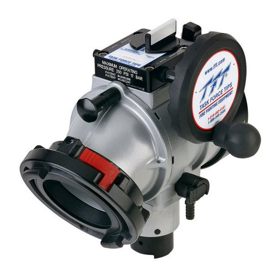
BALL INTAKE VALVE
JUMBO BALL INTAKE VALVE
SHORT
BALL INTAKE VALVE SHORT RC
TASK FORCE TIPS LLC
MADE IN USA • tft.com
©Copyright Task Force Tips, LLC 2002 - 2018
MANUAL:
Understand manual before use. Operation of this device without understanding the manual
and receiving proper training is a misuse of this equipment. Obtain safety information at
tft.com/serial-number
BALL INTAKE VALVE SHORT
W/ PARALLEL DRIVE GEARBOX
JUMBO BALL INTAKE VALVE
SHORT W/ PARALLEL DRIVE
GEARBOX
BALL INTAKE VALVE RC
Ball Intake Valve
Ball Intake Valve RC
Jumbo Ball Intake Valve
Jumbo Ball Intake Valve RC
BALL INTAKE VALVE
JUMBO BALL INTAKE VALVE
JUMBO BALL INTAKE VALVE
SHORT RC
3701 Innovation Way, Valparaiso, IN 46383-9327 USA
800-348-2686 • 219- 462-6161 • Fax 219-464-7155
BALL INTAKE VALVE
W/ PARALLEL DRIVE GEARBOX
JUMBO BALL INTAKE VALVE
W/ PARALLEL DRIVE GEARBOX
JUMBO BALL INTAKE VALVE RC
LIA-200 March 20, 2018 Rev19
Advertisement
Table of Contents

Related Manuals for Task Force Tips Ball Intake Valve


Summary of Contents for Task Force Tips Ball Intake Valve
- Page 1 JUMBO BALL INTAKE VALVE RC SHORT RC TASK FORCE TIPS LLC 3701 Innovation Way, Valparaiso, IN 46383-9327 USA 800-348-2686 • 219- 462-6161 • Fax 219-464-7155 MADE IN USA • tft.com ©Copyright Task Force Tips, LLC 2002 - 2018 LIA-200 March 20, 2018 Rev19...
-
Page 2: Table Of Contents
5.6 SUCTION SCREEN 5.7 PRESSURE LOSS 6.0 EXPLODED VIEWS AND PARTS LISTS 6.1 BALL INTAKE VALVE AB & AC SERIES EXPLODED VIEW AND PARTS LIST 6.2 JUMBO BALL INTAKE AP, AQ, AX & AZ SERIES EXPLODED VIEW AND PARTS LIST... -
Page 3: Meaning Of Signal Words
NOTICE 2.0 SAFETY Do not use AC current to operate the Ball Intake Valve RC or the Jumbo Ball Intake Valve RC. The WARNING Ball Intake Valve RC and the Jumbo Ball Intake Valve RC are 12 or 24VDC systems ONLY! Using the wrong power source could cause electrocution, resulting in death or serious injury. -
Page 4: General Information
Ball Intake Valves. The Ball Intake Valve and the Jumbo Ball Intake Valve are intended for use on the intake manifold of a fire engine. The valve is kept closed while the water supply from a hydrant or another pumper to the engine is being established. This prevents the pump from sucking air through the intake manifold and losing its prime. -
Page 5: Specifications
The electric motor and other components are ignition sources. The electric BIV should be operated only WARNING in areas where there is adequate ventilation and no hazard of flammable vapor buildup. ©Copyright Task Force Tips, LLC 2002 - 2018 LIA-200 March 20, 2018 Rev19... -
Page 6: Electrical Testing
NOTE: Override knob will only turn in one direction. To ensure proper voltage to the Ball Intake Valve RC, the wiring needs to be checked for proper gauge for the installed length of wire, and for proper termination. Also, ensure that the power source supplying the BIV RC and the grounding are adequate (other electrical loads on a shared circuit with the BIV RC may cause a low-voltage situation). -
Page 7: Changing Handwheel To Left Side (Rc Models)
4.7 BALL INTAKE VALVE RC MANUAL OVERRIDE The Ball Intake Valve RC is motor driven but also has an override handwheel for operating the valve manually. The override handwheel may also be used in the event of power failure. If electrical power is supplied to the control panel then the LED valve position display will track the valve’s position as the handwheel is moved. -
Page 8: Changing Offset Of Crank Handle
If the shaft shears off, the valve can be operated temporarily using a wrench on the ½” hex on the opposite side of the crankshaft. For repair instructions, see section 9.2 CRANKSHAFT OVERRIDE AND REPLACEMENT. ©Copyright Task Force Tips, LLC 2002 - 2018 LIA-200 March 20, 2018 Rev19... -
Page 9: Rc Valve Operation
Disabling the relief valve may Discharge Opening result in system damage or hose rupture if the system exceeds operating limits. The pressure relief valve meets the requirements of NFPA 1901. ©Copyright Task Force Tips, LLC 2002 - 2018 LIA-200 March 20, 2018 Rev19... -
Page 10: Suction Screen
5 PSI AT 2000 GPM TFT JUMBO BIV With 6” Coupling 3 PSI AT 2000 GPM 1000 1500 2000 2500 FLOW (GPM) Figure 5.7 Intake Valve Pressure Loss ©Copyright Task Force Tips, LLC 2002 - 2018 LIA-200 March 20, 2018 Rev19... -
Page 11: Exploded Views And Parts Lists
6.0 EXPLODED VIEWS AND PARTS LISTS 6.1 BALL INTAKE VALVE - AB & AC SERIES EXPLODED VIEW AND PARTS LIST SIDE B COUPLING/ SPOUT Index Description QTY Part # Index Description Part # GASKET - 6.0" V3240 3/8-16 X 5/16 SOCKET SET SCREW VT37-16SS312 1/4"... -
Page 12: Jumbo Ball Intake Ap, Aq, Ax & Az Series Exploded View And Parts List
6.2 JUMBO BALL INTAKE VALVE - AP, AQ, AX & AZ SERIES EXPLODED VIEW AND PARTS LIST 9 10 SIDE B COUPLING/ SPOUT Index Description QTY Part # Index Description Part # GASKET - 6.0" V3240 3/8-16 X 5/16 SOCKET SET SCREW VT37-16SS500 COUPLING SH 6.0"NHF X PSF7.0-NFS... -
Page 13: Motor Assembly Biv Rc & Jumbo Biv Rc Exploded View And Parts List
1/4-20 X ½ BUTTON HEAD CAP SCREW VT25-20BH500 MOTOR ENCLOSURE TUBE Y4641 CIRCUIT BOARD STANDOFF Y5538 VALVE MOTOR BOARD A5825 MOTOR ENCLOSURE CAP Y4642 SMALLEY RING V4295 ©Copyright Task Force Tips, LLC 2002 - 2018 LIA-200 March 20, 2018 Rev19... -
Page 14: Side B Outlet Options Exploded Views And Parts Lists
CUP SEAL A1597 A1596 COUPLING A4655N A4662N A4667N A4670N GASKET V3196 V3198 V3210 V3220 NFS RING/O-RING A4561/VO-248 A4566/VO-248 MATE A4730 PLASTIC STRIP A1291 CUP SEAL A1596 BALL VB.437 ©Copyright Task Force Tips, LLC 2002 - 2018 LIA-200 March 20, 2018 Rev19... - Page 15 A1292 A1291 A1293 CUP SEAL A1597 A1596 A1594 LOCK-OUT SCREW A1294 A1294 COUPLING A4124 A4125 A4277 MATE A4730 PLASTIC STRIP A1291 CUP SEAL A1596 BALL VB.437 VB.437 ©Copyright Task Force Tips, LLC 2002 - 2018 LIA-200 March 20, 2018 Rev19...
-
Page 16: Parallel Drive Gearbox [A] Exploded View And Parts List
AY307 O-RING-206 VO-206 GEAR BUSHING A1548 INDICATOR GEAR A1557 DOUBLE GEAR A1554 O-RING-214 VO-214 TRUNNION BUSHING A1549 1/4-20 X 3/4 SOCKET HEAD SCREW VT25-20SH750 INNER TRUNNION A1553 ©Copyright Task Force Tips, LLC 2002 - 2018 LIA-200 March 20, 2018 Rev19... -
Page 17: Worm Drive Gearbox [B] Exploded View And Parts List
GEAR THRUST WASHER A1502 12 DP WORM X220 INTEGRAL WORM GEAR & TRUNNION A1501 3/8-16 X 1-1/2 BUTTON HEAD SCREW VT37-16BH1.5 O-RING-214 VO-214 CRANK BUSHING A1513 GEAR SPACER A1511 ©Copyright Task Force Tips, LLC 2002 - 2018 LIA-200 March 20, 2018 Rev19... -
Page 18: Air Vent/Drain [C] Exploded View And Parts List
1/2" BARB X 1/4"NPTM NIPPLE XX329 FOLLOWER U251 3/8-24 X 3/8 DOG POINT H515 DRAIN HOUSING A1543 O-RING 115 VO-115 DRAIN SLEEVE A1541 O-RING-110 VO-110 DRAIN LEVER A1542 ©Copyright Task Force Tips, LLC 2002 - 2018 LIA-200 March 20, 2018 Rev19... -
Page 19: Trouble Shooting
Polarity reversed or poor connection Check wiring and correct polarity OPEN & CLOSE LED blink every No communication with Valve Motor Check Blue & White communication 4 seconds wiring ©Copyright Task Force Tips, LLC 2002 - 2018 LIA-200 March 20, 2018 Rev19... -
Page 20: Warranty
Task Force Tips LLC, 3701 Industrial Way, Valparaiso, Indiana 46383-9327 USA (“TFT”) warrants to the original purchaser of its Ball Intake Valve and Ball Intake Valve RC (“equipment”), and to anyone to whom it is transferred, that the equipment shall be free from defects in material and workmanship during the five (5) year period from the date of purchase. -
Page 21: Maintenance
10. Date of each service test and service test results 11. Damage and repairs, including who made the repairs and the cost of repair parts 12. Reason removed from service ©Copyright Task Force Tips, LLC 2002 - 2018 LIA-200 March 20, 2018 Rev19... -
Page 22: Crankshaft Override And Replacement
If crankshaft binds, consult Task Force Tips Service Department to determine the appropriate repairs. 6. If crankshaft rotates freely after clearing any obstructions, then a replacement crank shaft may be ordered from Task Force Tips and replaced as described below. -
Page 23: Templates
FLAT OR #4 SCREWS TO STOP ROTATION 0.964” [24.5mm] SQUARE Ø1.00” [25mm] 0.919” [23mm] OPTIONAL FLAT 1/8” [3mm] DIA (4) PLACES HOLE LOCATIONS FOR QUICK CONNECT PLUG TEMPLATE 4.2B ©Copyright Task Force Tips, LLC 2002 - 2018 LIA-200 March 20, 2018 Rev19... -
Page 24: Inspection Checklist
Operating an appliance that fails any of the above inspections is a misuse of this equipment. TASK FORCE TIPS LLC 3701 Innovation Way, Valparaiso, IN 46383-9327 USA 800-348-2686 • 219- 462-6161 • Fax 219-464-7155 MADE IN USA • tft.com ©Copyright Task Force Tips, LLC 2002 - 2018 LIA-200 March 20, 2018 Rev19...
Need help?
Do you have a question about the Ball Intake Valve and is the answer not in the manual?
Questions and answers