Advertisement
Quick Links
G-Force
INSTRUCTION FOR INSTALLATION, OPERATION, AND MAINTENANCE
DANGER
TASK FORCE TIPS LLC
MADE IN USA · tft.com
©Copyright Task Force Tips LLC 2010-2024
Understand manual before use. Operation of this device without understanding the manual and
receiving proper training is a misuse of this equipment. Obtain safety information at tft.com/
serial-number.
This equipment is intended for use by trained and qualified emergency services personnel for
firefighting. All personnel using this equipment shall have completed a course of education
approved by the Authority Having Jurisdiction (AHJ).
This instruction manual is intended to familiarize firefighters and maintenance personnel with the
operation, servicing, and safety procedures associated with this product. This manual should be
kept available to all operating and maintenance personnel.
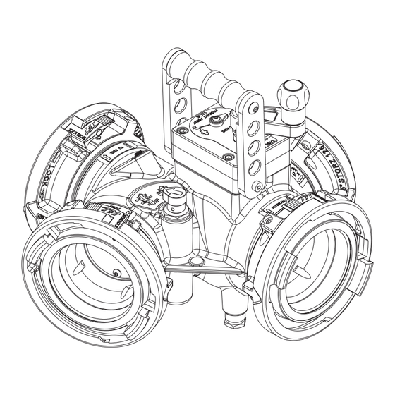
OASIS
HYDRANT ASSIST VALVE
3701 Innovation Way, Valparaiso, IN 46383-9327 USA
1
800-348-2686 · 219-462-6161 · Fax 219-464-7155
LIA-420 May 21, 2024 Rev08
Advertisement

Subscribe to Our Youtube Channel
Related Manuals for Task Force Tips OASIS


Summary of Contents for Task Force Tips OASIS
- Page 1 TASK FORCE TIPS LLC 3701 Innovation Way, Valparaiso, IN 46383-9327 USA 800-348-2686 · 219-462-6161 · Fax 219-464-7155 MADE IN USA · tft.com ©Copyright Task Force Tips LLC 2010-2024 LIA-420 May 21, 2024 Rev08...
- Page 2 6. Failure to follow these guidelines may result in death, burns or other severe injury. Fire and Emergency Manufacturers and Service Association, Inc. PO Box 147, Lynnfield, MA 01940 • www.FEMSA.org © 2020 FEMSA. All Rights Reserved. ©Copyright Task Force Tips LLC 2010-2024 LIA-420 May 21, 2024 Rev08...
- Page 3 6.0 MODIFICATION TO ALLOW SHUT OFF OF THE HYDRANT 7.0 WARRANTY 8.0 MAINTENANCE 8.0.1 TROUBLESHOOTING 8.1 SERVICE TESTING 8.2 REPAIR 9.0 EXPLODED VIEW AND PARTS LISTS 10.0 OPERATION AND INSPECTION CHECKLIST ©Copyright Task Force Tips LLC 2010-2024 LIA-420 May 21, 2024 Rev08...
- Page 4 To prevent mechanical damage, do not drop or throw equipment. GENERAL INFORMATION TFT’s Oasis Hydrant Assist Valve is a versatile valve that can be used as a hydrant booster, a gated wye, or for inline pumping during relay operations. In hydrant boosting operation, the valve is first connected to the hydrant and to the intake supply line on the first pumper. Inlet and outlet supply lines on a boost pumper are then connected to the valve to draw water directly from the hydrant connection and increase pressure/flow to the first pumper.
- Page 5 1. Remove the two 1/4-20 x 1/2” button head cap screws from the crank. 2. Place the crank in the desired position. REINSTALL CRANK IN THIS HOLE 3. Replace the screws. IF SHORTER SWING IS DESIRED Figure 4.2 ©Copyright Task Force Tips LLC 2010-2024 LIA-420 May 21, 2024 Rev08...
- Page 6 4. Open hydrant slowly when ready to flow. TASK FORCE TIPS ATTACK 800-348-2686 • Valparaiso, IN 46383-9327 INTAKE OASIS MODE 1 HYDRANT ASSIST Hydrant Pressure to Attack Engine VALVE Figure 5.2.1 ©Copyright Task Force Tips LLC 2010-2024 LIA-420 May 21, 2024 Rev08...
- Page 7 Source TASK FORCE TIPS 800-348-2686 • Valparaiso, IN 46383-9327 ASSIST OASIS MODE 2 BOOST HYDRANT ASSIST VALVE Source Pressure to Assist Pumper Boosted Flow to Attack Engine Figure 5.2.4 ©Copyright Task Force Tips LLC 2010-2024 LIA-420 May 21, 2024 Rev08...
- Page 8 “HYDRANT” port to “TO RELAY PUMP INLET” port and allowing water to flow from the “FROM PUMP RELAY” port to the “TO FIRE” port. Figure 5.3.2 ©Copyright Task Force Tips LLC 2010-2024 LIA-420 May 21, 2024 Rev08...
- Page 9 (TOTAL PRESSURE) NOTE: (1) Flow rates calculated assuming that 10 psi residual is remaining at the inlet to the attack pumper. Table 5.4 VALVE PRESSURE LOSS OASIS HYDRANT ASSIST VALVE PRESSURE LOSS SIDE PORT FLOW 57 PSI at 2000 GPM...
- Page 10 WARRANTY Task Force Tips LLC, 3701 Innovation Way, Valparaiso, Indiana 46383-9327 USA (“TFT”) warrants to the original purchaser of its products (“equipment”), and to anyone to whom it is transferred, that the equipment shall be free from defects in material and workmanship during the five (5) year period from the date of purchase for mechanical components, and the two (2) year period from the date of purchase for electrical components.
- Page 11 Repair parts and service procedures are available for those wishing to perform their own repairs. Task Force Tips assumes no liability for damage to equipment or injury to personnel that is a result of user service. Contact the factory or visit the web site at tft.com for parts lists, exploded views, test procedures and troubleshooting guides.
- Page 12 Operating equipment that has failed the checklist is a misuse of this equipment. TASK FORCE TIPS LLC 3701 Innovation Way, Valparaiso, IN 46383-9327 USA 800-348-2686 · 219-462-6161 · Fax 219-464-7155 MADE IN USA · tft.com ©Copyright Task Force Tips LLC 2010-2024 LIA-420 May 21, 2024 Rev08...
Need help?
Do you have a question about the OASIS and is the answer not in the manual?
Questions and answers