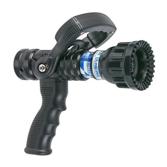
Task Force Tips ULTIMATIC Instructions For Installation, Safe Operation And Maintenance
Hand held automatic pressure control nozzles
Hide thumbs
Also See for ULTIMATIC:
- Instructions for installation, operation and maintenance (8 pages) ,
- Manual (24 pages) ,
- Instructions for safe operation and maintenance (12 pages)
Table of Contents
Advertisement
Quick Links
ULTIMATIC, MID-MATIC & HANDLINE
INSTRUCTIONS FOR INSTALLATION, SAFE OPERATION AND MAINTENANCE
WARNING
WARNING
WARNING
TASK FORCE TIPS, INC.
MADE IN USA • www.tft.com
©Copyright Task Force Tips, Inc. 2002 - 2012
TFT HAND HELD AUTOMATIC
PRESSURE CONTROL NOZZLES
Read instruction manual before use. Operation of this nozzle without understanding the manual
and receiving proper training can be dangerous and is a misuse of this equipment. Call 800-348-
2686 with any questions.
This instruction manual is intended to familiarize fi refi ghters and maintenance personnel with
the operation, servicing and safety procedures associated with the Ultimatic, Mid-Matic and
Handline fi re fi ghting nozzles.
This manual should be kept available to all operating and maintenance personnel.
ULTIMATIC
HANDLINE
MID-MATIC
3701 Innovation Way, Valparaiso, IN 46383-9327 USA
800-348-2686 • 219- 462-6161 • Fax 219-464-7155
LIN-030 February 14, 2012 Rev13
Advertisement
Table of Contents

Related Manuals for Task Force Tips ULTIMATIC


Summary of Contents for Task Force Tips ULTIMATIC
- Page 1 This instruction manual is intended to familiarize fi refi ghters and maintenance personnel with WARNING the operation, servicing and safety procedures associated with the Ultimatic, Mid-Matic and Handline fi re fi ghting nozzles. This manual should be kept available to all operating and maintenance personnel.
-
Page 2: Table Of Contents
2.0 GENERAL INFORMATION The Task Force Tips Ultimatic, Mid-Matic and Handline nozzles are designed to provide excellent performance under most fi re fi ghting conditions. Their rugged construction is compatible with the use of fresh water (see section 3.2 for saltwater use) as well as fi... -
Page 3: Various Models And Terms
* Other threads, coupling sizes, or connector styles can be specifi ed at time of order. Ultimatic, Mid-Matic and Handline nozzles are available in several models. Some common models are shown in fi gure 1. Nozzle must be mated to a hose line with matched threads. Mismatched or damaged threads may CAUTION cause nozzle to leak or uncouple from hose under pressure and could cause injury. -
Page 4: Mechanical Specifications
2.2 COLOR CODED VALVE HANDLE AND PISTOL GRIP The TFT ULTIMATIC, MID-MATIC & HANDLINE with lever type valve handles are supplied with black valve handle covers and pistol grips. The handle covers and pistol grips are available from TFT in various colors for those departments wishing to color code the nozzle to the discharge controls. - Page 5 Do not attempt to regain control of nozzle while fl owing water. Fire streams are capable of injury and damage. Do not direct water stream to cause injury or CAUTION damage to persons or property. ©Copyright Task Force Tips, Inc. 2002 - 2012 LIN-030 February 14, 2012 Rev13...
-
Page 6: Reach & Trajectory
4.2.1 PATTERN CONTROL TFT’s ULTIMATIC, MID-MATIC and HANDLINE have full pattern control from straight stream to wide fog. Turning the STREAM SHAPER clockwise (as seen from the operating position behind the nozzle) moves the SHAPER to the straight stream position. -
Page 7: Use Of Ultimatic, Mid-Matic & Handline Nozzles
Performance tests shall be conducted on the Ultimatic, Mid-Matic and Handline nozzle after a repair, or anytime a problem is reported to verify operation in accordance with TFT test procedures. Consult factory for the procedure that corresponds to the model and serial number of the nozzle. -
Page 8: Warranty
Task Force Tips, Inc., 3701 Innovation Way, Valparaiso, Indiana 46383-9327 USA (“TFT”) warrants to the original purchaser of its Ultimatic, Mid-Matic, and Handline series nozzles (“equipment”), and to anyone to whom it is transferred, that the equipment shall be free from defects in material and workmanship during the fi ve (5) year period from the date of purchase. -
Page 9: Nozzle Flow Charts
(1) Number in each box indicates flow (LPM). (2) Flows may vary with brand or condition of hose. (3) Flows are approximate and do not reflect losses in preconnect piping. (4) 1 BAR = 100 KPA ©Copyright Task Force Tips, Inc. 2002 - 2012 LIN-030 February 14, 2012 Rev13... - Page 10 (1) Number on top in each box indicates flow (LPM), and number on bottom indicates nozzle reaction (KG). (2) Flows may vary with brand or condition of hose. (3) Flows are approximate and do not reflect losses in preconnect piping. ©Copyright Task Force Tips, Inc. 2002 - 2012 LIN-030 February 14, 2012 Rev13...
- Page 11 (1) Number on top in each box indicates flow (LPM), and number on bottom indicates nozzle reaction (KG). (2) Flows may vary with brand or condition of hose. (3) Flows are approximate and do not reflect losses in preconnect piping. ©Copyright Task Force Tips, Inc. 2002 - 2012 LIN-030 February 14, 2012 Rev13...
-
Page 12: Inspection Checklist
7) Shaper turns freely and adjusts pattern through full range. 8) Shaper turns into full fl ush and out of fl ush with normal fl ow and pressure restored. Any Ultimatic, Mid-Matic or Handline nozzle failing any part of the inspection checklist is unsafe WARNING and must have the problem corrected before use.
Need help?
Do you have a question about the ULTIMATIC and is the answer not in the manual?
Questions and answers