Table of Contents
Advertisement
Quick Links
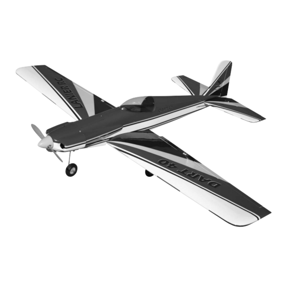
Dart ARF
Thank you for purchasing the Lanier R/C Dart. We are sure you
will be happy with the quality of the kit and happy with the flying
characteristics of the Dart. Because of it's light weight,the Dart will
fly exceptionally well on a standard .40 size motor. This makes the
Dart a perfect "first time" low wing airplane. The gentle flying char-
acteristics and good aerobatic ability make is a joy to fly.
Lanier R/C, INC. P.O. Box 458 Oakwood, Ga. 30566 PH 770 532 6401 ©copyright 1989 Lanier R/C, Inc.
1
1
Advertisement
Table of Contents

Related Manuals for Lanier R/C Dart ARF


Summary of Contents for Lanier R/C Dart ARF
- Page 1 Dart a perfect “first time” low wing airplane. The gentle flying char- acteristics and good aerobatic ability make is a joy to fly. Lanier R/C, INC. P.O. Box 458 Oakwood, Ga. 30566 PH 770 532 6401 ©copyright 1989 Lanier R/C, Inc.
- Page 2 Sloppy linkage and over speeding the plane will cause flutter which is not covered in the warranty. Lanier R/C is proud of the care and attention that goes into the manufacture of parts for its model kits. The company warrants that for a period of 90 days, it will replace, at the buyers request, any parts or material shown to the company’s satisfaction to have been defec-...
-
Page 3: Wing Assembly
Mount the servo using the hardware sup- plied with the radio.The output arm should be to the rear. Lanier R/C, INC. P.O. Box 458 Oakwood, Ga. 30566 PH 770 532 6401 © copyright 1989 Lanier R/C... - Page 4 1/2” in from the end of the wire. Drill a 1/16” hole at each location and install the #2 screws. Repeat for the other wing. Lanier R/C, INC. P.O. Box 458 Oakwood, Ga. 30566 PH 770 532 6401 © copyright 1989 Lanier R/C...
-
Page 5: Tail Assembly
Do the same to both sides of the fin. Lanier R/C, INC. P.O. Box 458 Oakwood, Ga. 30566 PH 770 532 6401 © copyright 1989 Lanier R/C... - Page 6 You must install the elevator joiner wire before installing stab. The elevator wire cannot be installed after the stab is glued in place. remove covering Lanier R/C, INC. P.O. Box 458 Oakwood, Ga. 30566 PH 770 532 6401 © copyright 1989 Lanier R/C...
- Page 7 (about 1”) and glue the hinges using thin CA. Flex in the other direction and apply glue on the other side of the hinges. Lanier R/C, INC. P.O. Box 458 Oakwood, Ga. 30566 PH 770 532 6401 © copyright 1989 Lanier R/C...
-
Page 8: Engine Mounting
If you use a spinner such as the Goldberg which is offset at the rear you will need to add 1/4” to the length. Lanier R/C, INC. P.O. Box 458 Oakwood, Ga. 30566 PH 770 532 6401 © copyright 1989 Lanier R/C... - Page 9 Be sure and use thread lock on the bolts. The engine is shown mounted sideways, it can me mounted in any position you desire, upside down or at an angle. Lanier R/C, INC. P.O. Box 458 Oakwood, Ga. 30566 PH 770 532 6401 © copyright 1989 Lanier R/C...
-
Page 10: Cowl Mounting
Tape in place about 1” back from the fire- wall with the front edge flush with the fire- wall..Two on top, two on the bottom. Lanier R/C, INC. P.O. Box 458 Oakwood, Ga. 30566 PH 770 532 6401 © copyright 1989 Lanier R/C... -
Page 11: Radio Installation
Remove the cowl and open the holes up with a 3/32” drill. Locate the control horns, nut plates and #2 screws. Lanier R/C, INC. P.O. Box 458 Oakwood, Ga. 30566 PH 770 532 6401 © copyright 1989 Lanier R/C... - Page 12 Make sure the aileron is centered and mark the location on the wire where it crosses the servo arm. Lanier R/C, INC. P.O. Box 458 Oakwood, Ga. 30566 PH 770 532 6401 © copyright 1989 Lanier R/C...
-
Page 13: Push Rod Installation
You can use a match if you don’t have a heat Repeat for the other aileron. gun. Lanier R/C, INC. P.O. Box 458 Oakwood, Ga. 30566 PH 770 532 6401 © copyright 1989 Lanier R/C... - Page 14 Reinstall the clevis on each pushrod with to remove the covering and seal it at the a silicone keeper and attach to the control same time. horns. Lanier R/C, INC. P.O. Box 458 Oakwood, Ga. 30566 PH 770 532 6401 © copyright 1989 Lanier R/C...
-
Page 15: Servo Installation
Attach the other connector to the inner most hole on a double sided four hole (3/4”) servo arm for the rudder and nose gear. Lanier R/C, INC. P.O. Box 458 Oakwood, Ga. 30566 PH 770 532 6401 © copyright 1989 Lanier R/C... -
Page 16: Fuel Tank Installation
The fuel pickup is straight with about 1/2” on each side of the cap. Lanier R/C, INC. P.O. Box 458 Oakwood, Ga. 30566 PH 770 532 6401 © copyright 1989 Lanier R/C... - Page 17 Attach fuel line (not supplied)from the vent line to the muffler pressure tap and from the fuel pick up line to the carb. Lanier R/C, INC. P.O. Box 458 Oakwood, Ga. 30566 PH 770 532 6401 © copyright 1989 Lanier R/C...
-
Page 18: Battery & Receiver Installation
Be sure to wrap the receiver in at least 1/2” of foam rubber. Lanier R/C, INC. P.O. Box 458 Oakwood, Ga. 30566 PH 770 532 6401 © copyright 1989 Lanier R/C... -
Page 19: Parts List
2. 3mm x 20mm bolts 3. 3mm aircraft lock nuts 4. 4mm x 25mm bolts 5. 4mm blind nuts 6. flat washers Lanier R/C, INC. P.O. Box 458 Oakwood, Ga. 30566 PH 770 532 6401 © copyright 1989 Lanier R/C... -
Page 20: Equipment Required
11. Pliers (needle nose) 12. Mixing sticks 13. 36” yard stick or tape measure 14. Scissors 15. Moto tool with sanding drum. Lanier R/C, INC. P.O. Box 458 Oakwood, Ga. 30566 PH 770 532 6401 © copyright 1989 Lanier R/C...
Need help?
Do you have a question about the Dart ARF and is the answer not in the manual?
Questions and answers