Lanier R/C Stinger ARF Assembly Instructions Manual
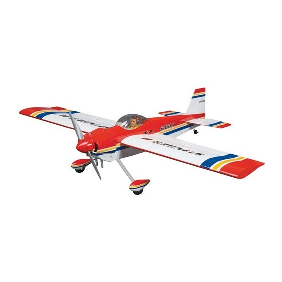
Lanier r/c stinger arf model aircraft
Hide thumbs
Also See for Stinger ARF:
- Instruction manual (24 pages) ,
- Assembly instructions manual (22 pages) ,
- Owner's manual (17 pages)
Table of Contents
Advertisement
Quick Links
Assembly Instructions
TM
Important Information:
Please inspect the plane before beginning to assemble to make sure you are happy
with it. After assembly has begun you cannot return the kit. If you find a problem
before beginning to assemble the plane you must contact us, please do not return
it to the dealer. Due to temperature changes the plane may develop some wrinkles
in the covering that you will need to remove with an iron. Be sure to seal the edges
down first so that you do not cause the covering to shrink and leave exposed areas
of wood. The model is built light to ensure good flight characteristics. With the
power available from the new breed of engines, it is necessary to use throttle man-
agement in order not to overstress the airframe. You must maintain good tight con-
trol linkage with no slop, good servos with plenty of power, and good servo arms
to protect against flutter. Sloppy linkage and overspeeding the plane will cause flut-
ter which is not covered in the warranty. Lanier R/C is proud of the care and atten-
tion that goes into the manufacture of parts for its model kits. The company war-
rants that for a period of 30 days, it will replace, at the buyers request, any parts
Lanier R/C, INC. P.O. Box 458 Oakwood, Ga. 30566 PH 770 532 6401
©copyright 1989 Lanier R/C, Inc.
1
1
Advertisement
Table of Contents

Related Manuals for Lanier R/C Stinger ARF


Summary of Contents for Lanier R/C Stinger ARF
- Page 1 Sloppy linkage and overspeeding the plane will cause flut- ter which is not covered in the warranty. Lanier R/C is proud of the care and atten- tion that goes into the manufacture of parts for its model kits. The company war- rants that for a period of 30 days, it will replace, at the buyers request, any parts Lanier R/C, INC.
- Page 2 Bigger does fly better but some of the hardware used on small plane will not be suitable for a giant scale. Lanier R/C, INC. P.O. Box 458 Oakwood, Ga. 30566 PH 770 532 6401 © copyright 1989 Lanier R/C...
- Page 3 Assembly Instructions Lanier R/C, INC. P.O. Box 458 Oakwood, Ga. 30566 PH 770 532 6401 © copyright 1989 Lanier R/C...
-
Page 4: Wing Assembly
1/2” exposed. make a mark 1/2” in from one end. Using an exacto knife, remove the covering Lanier R/C, INC. P.O. Box 458 Oakwood, Ga. 30566 PH 770 532 6401 © copyright 1989 Lanier R/C... -
Page 5: Tail Assembly
Do the same to both sides of the fin. Lanier R/C, INC. P.O. Box 458 Oakwood, Ga. 30566 PH 770 532 6401 © copyright 1989 Lanier R/C... - Page 6 Cut carefully and cut only the covering, don’t cut the balsa underneath as this would weaken the stab and fin. remove covering remove covering Lanier R/C, INC. P.O. Box 458 Oakwood, Ga. 30566 PH 770 532 6401 © copyright 1989 Lanier R/C...
- Page 7 Be careful not to put pres- sure on any of the surfaces, after all the wires are installed we will adjust the ten- sion. Lanier R/C, INC. P.O. Box 458 Oakwood, Ga. 30566 PH 770 532 6401 © copyright 1989 Lanier R/C...
-
Page 8: Landing Gear
When all wires are installed adjust each one so there is no play in the rod. Don’t over tighten the clevis so as not to twist or bend the stab and fin. Lanier R/C, INC. P.O. Box 458 Oakwood, Ga. 30566 PH 770 532... - Page 9 Install the wheel using the 3mm wheel collar. Tail Wheel Bracket Lanier R/C, INC. P.O. Box 458 Oakwood, Ga. 30566 PH 770 532 6401 © copyright 1989 Lanier R/C...
- Page 10 Take the two 3/8” x 1-3/8” x 7/8” wooden blocks and place on this line at the front of the wing bolt reinforcement plate. Lanier R/C, INC. P.O. Box 458 Oakwood, Ga. 30566 PH 770 532 6401 © copyright 1989 Lanier R/C...
-
Page 11: Engine Mounting
Thrust line Lanier R/C, INC. P.O. Box 458 Oakwood, Ga. 30566 PH 770 532 6401 © copyright 1989 Lanier R/C... -
Page 12: Cowl Mounting
Secure the cowl in place using side at the top. the 3mm screws. Lanier R/C, INC. P.O. Box 458 Oakwood, Ga. 30566 PH 770 532 6401 © copyright 1989 Lanier R/C... -
Page 13: Radio Installation
Assembly Instructions Radio Installation Install the aileron servos in the wing using the hardware that comes with the radio. The servo should be turned so the arm is position toward the rear of the wing and on the outboard side of the servo. Use the factory installed nylon fishing line to pull the aileron lead to the hole in the cen- ter of the wing. - Page 14 E-Z connector. This set up shows a Fox 4.2, if you are using a different engine you will have to adjust accordingly. Lanier R/C, INC. P.O. Box 458 Oakwood, Ga. 30566 PH 770 532 6401 © copyright 1989 Lanier R/C...
- Page 15 5” to 5-1/2” behind the leading edge. For all out aero- batics you can go back to 6-1/2” behind the leading edge. Lanier R/C, INC. P.O. Box 458 Oakwood, Ga. 30566 PH 770 532 6401 © copyright 1989 Lanier R/C...
-
Page 16: Control Throws
All you can get Aileron All you can get Rudder All you can get Center of Gravity 5 to 5-1/2” behind leading edge Lanier R/C, INC. P.O. Box 458 Oakwood, Ga. 30566 PH 770 532 6401 © copyright 1989 Lanier R/C... -
Page 17: Airframe Components
1. 4mm screws 5. Aluminum bracket 2. wooden mount blocks 6. Flying wire brackets 7. 2mm bolts 8. 2mm nuts 9. 2mm screws Lanier R/C, INC. P.O. Box 458 Oakwood, Ga. 30566 PH 770 532 6401 © copyright 1989 Lanier R/C... -
Page 18: Equipment Required
11. Pliers (needle nose) 12. Mixing sticks 13. 36” yard stick or tape measure 14. Scissors 15. Moto tool with sanding drum. Lanier R/C, INC. P.O. Box 458 Oakwood, Ga. 30566 PH 770 532 6401 © copyright 1989 Lanier R/C...
Need help?
Do you have a question about the Stinger ARF and is the answer not in the manual?
Questions and answers