Advertisement
Quick Links
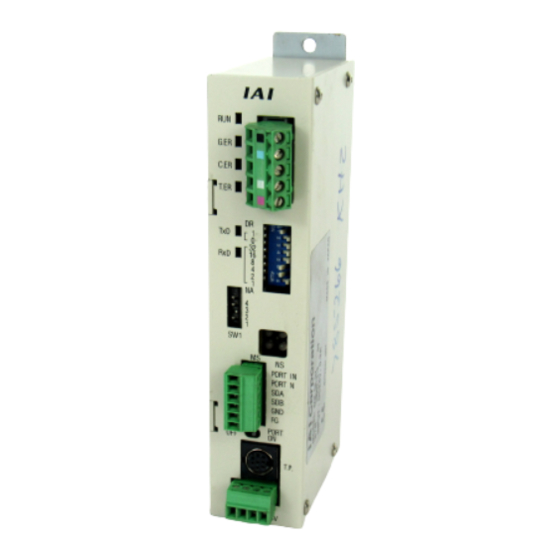
RCM-GW Gateway Unit
First Step Guide
First Edition
Thank you for purchasing our product.
Make sure to read the Safety Guide and detailed Instruction Manual (DVD) included with the product in addition to
this First Step Guide to ensure correct use.
This Instruction Manual is original.
Warning : Operation of this equipment requires detailed installation and operation instructions which are
provided on the DVD Manual included in the box this device was packaged in. It should be retained
with this device at all times.
A copy of the DVD Manual can be requested by contacting your nearest IAI Sales Office listed at
the back cover of the Instruction Manual or on the First Step Guide.
Using or copying all or part of this Instruction Manual without permission is prohibited.
The company names, names of products and trademarks of each company shown in the sentences are registered
trademarks.
Product Check
A standard configuration of this product is comprised of the following parts.
If you find any fault in the contained model or any missing parts, contact us or our distributor.
1. Parts
No.
Part Name
Model
Refer to "How to read the model plate" and
1
Controller Main Body
"How to read the model".
Accessories
DeviceNet type
SMSTB2.5/5-ST-5.08AU
Fieldbus
(Supplier : PHOENIX CONTACT)
2
CC-Link type
Connector
PROFIBUS type
Prepare Dsub 9-pin (female) connector.
SIO Communication
MC1.5/6-ST-3.5
3
Connector Plug
(Supplier : PHOENIX CONTACT)
Power Supply Input
MC1.5/4-ST-3.81
4
Connector Plug
(Supplier : PHOENIX CONTACT)
DeviceNet type
Please prepare separately
1301/2W, 1101/2W enclosed one unit
Terminal
CC-Link type
5
each
Resistance
Built-in
PROFIBUS type
(selected on terminal resistance switch)
6
First Step Guide
7
Instruction Manual (DVD)
8
Safety Guide
2. Instruction Manuals related to this product, which are contained in the Instruction Manual
(DVD).
No.
Name
1
DeviceNet Gateway Unit RCM-GW-DV Instruction Manual
2
CC-Link Gateway Unit RCM-GW-CC Instruction Manual
3
PROFIBUS Gateway Unit RCM-GW-PR Instruction Manual
4
ACON-C/CG Controller Positioner Type Instruction Manual
5
ACON-SE Controller Serial Communication Type Instruction Manual
6
PCON-C/CG/CF Controller Positioner Type Instruction Manual
7
PCON-SE Controller Serial Communication Type Instruction Manual
8
SCON Controller Instruction Manual
9
ERC2 Actuator with integrated Controller Instruction Manual (SIO type)
3. How to read the model plate
Model
MODEL RCM-GW-DV
SERIAL No. 800056144
Serial number
4. How to read the model
• R C M - G W - D V : D e v i c e N e t G a t e w a y U n i t
• R C M - G W - C C : C C - L i n k G a t e w a y U n i t
• R C M - G W - P R : P R O F I B U S G a t e w a y U n i t
1D
1. RCM-GW-DV
Item
Communication Protocol DeviceNet2.0 (certified interface)
For Communication
Baud Rate
Communication Cable
Length
(Note 1)
Number of Occupied Nodes 1 node
Communication Power
Supply
Communications Cable
Note 1 Refer to the instruction manuals for the master unit and the mounted programmable logic controller (stated as PLC
from now on) when a T-junction communication is to be conducted.
2. RCM-GW-CC
Item
Communication Protocol CC-Link Ver1.10/Ver2
Baud Rate
Communication System
Synchronization System
Transmission Path
Format
Error Control System
Remarks
Number of Occupied Stations
Communication Cable
Length
(Note 2)
Communications Cable
Note 1 When the host CC-Link master unit is Ver.1, the available RCM-GW-CC is limited to Ver.1.10. Even if the host CC-Link
master unit is Ver.2, RCM-GW-CC Ver.1.10 is connectable, but the available functions are limited.
[Refer to 5. Operation Modes and Main Functions [2] RCM-GW-CC or Instruction Manual (DVD)]
Applicable Cable Size
Note 2 Refer to the instruction manuals for the master unit and the mounted programmable logic controller (stated as PLC
0.3mm
2
(AWG22)
from now on) when a T-junction communication is to be conducted.
Applicable Cable Size
*1
CRC : Cyclic Redundancy Check It is a data error detection method often used for the synchronous transmission
1.25mm
2
(AWG16)
3. RCM-GW-PR
1211 1/4W
Item
Communication Protocol
Communication System
Baud Rate
Communication Cable
Length
(Type A Cable)
Number of Occupied Nodes 1 node
Communications Cable
4. Common Specifications
Item
Manual No.
Power Supply
ME0168
Current Consumption
ME0169
Heat Generation
ME0177
Connectable Models
ME0176
Number of Max. Controllable
ME0171
Axes
ME0170
Communication
ME0163
Protocol
ME0161
Communication System Start-Stop Synchronization System Half-Duplex Communication
ME0159
Baud Rate
Error Control System
Communication Cable
Length
Communications Cable
Surrounding air
MADE IN JAPAN
temperature
Surrounding humidity
Surrounding
environment
Surrounding storage
temperature
Surrounding storage
humidity
Vibration durability
Protection class
Cooling Method
Insulation Resistance
Product Life
External Dimensions
Weight
*1
CRC : Cyclic Redundancy Check It is a data error detection method often used for the synchronous transmission
Basic Specifications
Specification
Master/Slave Connection
Bit Strobe
Polling
Cyclic
500k/250k/125kbps
Max. Branch Line
Total Branch Line
Baud Rate
Max. Network Length
Length
Length
500kbps
100m
39m
250kbps
250m
6m
78m
125kbps
500m
156m
(Note) When DeviceNet dedicated thick cable is used
Voltage 24V DC10% Current Consumption 60mA Externally Supplied (Supplied from
DeviceNet communication cable side)
DeviceNet dedicated cable
Specification
(Note 1)
10M/5M/2.5M/625k/156kbps
Broadcast polling system
Frame synchronization system
Bus format (EIA RS485 conformance 3-line type)
X
X
1)
CRC (X
16
12
5
*1
Remote Device Station [Refer to Field Network Wirings and Settings Section]
Baud Rate
10Mbps
5Mbps
2.5Mbps
625kbps
156kbps
Total Cable
100m
160m
400m
900m
1200m
Length
CC-Link dedicated cable
Specification
PROFIBUS-DP (RS485 conformance)
Hybrid System (Master-Slave System or Token Passing System)
9.6k to 12Mbps (Automatic Following to the Master)
93.75/45.45/
Baud Rate
12/6/3Mbps
1.5Mbps
500kbps
187.5kbps
19.2/9.6kbps
Total Cable
100m
200m
400m
1000m
1500m
Length
Type A Cable for PROFIBUS-DP (Standard EN50170)
Specification
24V DC10
MAX. 300mA
7.2W
ERC2, PCON-C/CG/SE, ACON-C/CG/SE, SCON
16-axis (There is a limitation for RCM-GW-CC depending on the Operation Mode
[Refer to 5. Operation Modes and Main Functions [2] RCM-GW-CC or Instruction
Manual (DVD)])
RS485 conformance
230.4kbps
Non parity bit, CRC
*1
Total Cable Length 100m or less
Twisted-pair shielded cable
(Recommended : Taiyo Cabletec Corporation K-SB/20276 Length [m] 2P AWG22)
0 to 40C
85%RH or less (non-condensing)
[Refer to Installation Environment section]
10 to 65C
90%RH or less (non-condensing)
XYZ Each direction 10 to 57Hz Pulsating amplitude 0.035mm (continuous) 0.075mm (intermittent)
57 to 150Hz 4.9m/s
2
(continuous) 9.8m/s
2
(intermittent)
IP20
Natural air-cooling
Between power supply terminal and FG 500V DC 10M or more
(Reference) 5 to 10 years: It varies significantly by the effects of the usage condition
(especially temperature).
35W 178.5H 68.1D [mm]
Approx. 480g
5. Operation Modes and Main Functions
Operation Mode can be selected on the mode switch located on the front panel. [Refer to Field Network
Wirings and Settings Section]
[1] RCM-GW-DV
Position Number Specification
Direct Numeric Specification
Main Functions
Mode
Mode
Position Data Direct
×
○
Specification Movement
Velocity and Acceleration Direct Setup
×
○
Pressing Operation
○
○
Current Position Reading
×
○
Number of Positions Specification
(Note 4)
○
×
Completed Position Number Reading
○
×
Signal Reading for Each Status
○
○
Number of Max. Connectable Axes
16
16
Number of Selectable (Valid) Axes
0 to 15
0 to 15
Max. Value for Position Data
(Note 3)
Position Table Setting
9999.99
Specification (mm or deg)
[2] RCM-GW-CC
Direct Numeric Specification Mode
Position Number
Main Functions
Specification
Position Data
Normal
Pressing
Mode
Limit Mode
Positioning Mode
Available Mode
Position Data Direct
×
○
○
Specification Movement
Velocity and Acceleration Direct Setup
×
×
○
Pressing Operation
○
×
×
Current Position Reading
×
○
○
Number of Positions Specification
(Note 4)
○
×
×
Completed Position Number Reading
○
×
×
Number of Max. Connectable Axes
14
14
7
Number of Selectable (Valid) Axes
0 to 13
0 to 13
0 to 6
Max. Value for Position Data
Position Table
327.67
327.67
9999.99
Specification (mm or deg)
Setting
RCM-GW-CC Ver1.10
○
Corresponding Model
RCM-GW-CC Ver2
○
Corresponding Model
[3] RCM-GW-PR
Position Number
Direct Numeric Specification
Main Functions
Specification Mode
Mode
Position Data Direct
×
○
Specification Movement
Velocity and Acceleration Direct Setup
×
○
Pressing Operation
○
○
Current Position Reading
×
○
Number of Positions Specification
(Note 4)
○
×
Completed Position Number Reading
○
×
Signal Reading for Each Status
○
○
Number of Max. Connectable Axes
16
16
Number of Selectable (Valid) Axes
0 to 15
0 to 15
Max. Value for Position Data
Position Table Setting
9999.99
(Note 3)
Specification (mm or deg)
Note 1 Although an operation cannot be performed with specifying values directly, it is available to operate by rewriting the
data on the position table from the write command.
Please note, however, that the EEPROM has a 100,000 write limitation. Consider the effect of this mode with regard to
product lifespan.
Note 2 Direct reading cannot be performed since it is not the constant output. However, reading is available from the read
command.
Note 3 This is the maximum value that can be written to the data field; however, the maximum value input should not exceed
the actuator stroke.
Note 4 The number of available positions varies according to which PIO pattern is selected through the Operation Mode
parameter.
ERC2 Standard, PCON-C/CG/SE, ACON-C/CG and SCON
Limitation in Number of
PIO Pattern (Parameter No.25)
Positions by PIO Pattern
Select
0
1
2
3
Solenoid
Zone Signal
Position
Operation Type
Standard
Valve Type
Type
Zone Type
Position Number
ERC2
8
×
16
16
Specification Mode
Command
8
×
16
16
Specification Mode
Positioning
Teaching
256-point
512-point
Operation Type
Mode
Mode
Mode
Mode
PCON
Position Number
ACON
64
64
256
512
Specification Mode
SCON
Command
64
64
256
512
Specification Mode
[Refer to the instruction manual of each controller for PIO pattern details.]
Command Specification Mode
Positioner
Simplified Direct
Operation
Value Operation
(Note 1)
○
△
(Note 1)
(Note 1)
△
△
△
(Note 1)
△
(Note 1)
△
(Note 2)
○
○
×
○
○
○
○
16
16
0 to 15
0 to 15
(Note 3)
(Note 3)
9999.99
9999.99
Command Specification Mode
Positioner
Simplified Direct
Operation
Value Operation
○
(Note 1)
○
△
○
(Note 1)
(Note 1)
△
△
○
△
(Note 1)
△
(Note 1)
○
△
(Note 2)
○
×
○
×
×
○
○
3
16
16
0 to 2
0 to 15
0 to 15
(Note 3)
9999.99
(Note 3)
9999.99
(Note 3)
×
Command Specification Mode
Positioner
Simplified Direct
Operation
Value Operation
(Note 1)
△
○
(Note 1)
(Note 1)
△
△
△
(Note 1)
△
(Note 1)
△
(Note 2)
○
○
×
○
○
○
○
16
16
0 to 15
0 to 15
9999.99
(Note 3)
9999.99
(Note 3)
ERC2-SE
ACON-SE
PCON-SE
4
5
SIO
SIO Type
64
64
64
64
Electromagnetic
Electromagnetic
SIO Type
Valve Mode 1
Valve Mode 2
7
×
64
7
×
64
Advertisement

Related Manuals for IAI RCM-GW


Summary of Contents for IAI RCM-GW
- Page 1 (Supplier : PHOENIX CONTACT) CC-Link type ○ × Note 1 When the host CC-Link master unit is Ver.1, the available RCM-GW-CC is limited to Ver.1.10. Even if the host CC-Link Connector Corresponding Model PROFIBUS type Prepare Dsub 9-pin (female) connector.
- Page 2 HK-SB/20276 × L PORT IN terminal resistance. 2P × AWG22 PORT N DeviceNet/CC-Link/PROFIBUS Gateway Unit DeviceNet Type Teaching Pendant <Model RCM-GW-DV> CC-Link Type <Model RCM-GW-CC> Note E-Con connector (Manufactured by AMP : 4-1473562-4) Switching ON/OFF of the teaching PROFIBUS Type RCM-GW-DV...
- Page 3 (Class-III grounding) Baud rate setting switch Note : RCM-GW-PR is equipped with a built-in terminal resistance. If RCM-GW-PR is connected as the terminal, Station number setting switch turn the terminal resistance setting switch ON. If a connector that is equipped with a terminal resistance is...
-
Page 4: Troubleshooting
There is no sent data. Power Supply It can be recovered with a rebuild of the settings. 1) Supply the power to the IAI controller that is connected to Gateway Unit. Refer to Instruction Manual for the details of the CC-Link status check. −... - Page 5 SIO Communication Status Display LEDs Color Indication Description Flashing Data is being sent (from Gateway Unit to IAI controller). Data sending is being stopped (from Gateway Unit to IAI controller). Flashing Data is being received (from IAI controller to Gateway Unit).