Advertisement
Quick Links
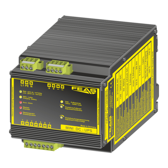
Betriebsanleitung
LDR30MH24
Bitte sorgfältig beachten!
1. Funktionsweise
Das LDR30MH24 ist ein 24V-Schaltnetzteil mit
integriertem Akkumulator um die Versorgung eines
Verbrauchers bei Netzausfall aufrecht zu erhalten.
LED-Anzeigen / LED-Display
Normalzustand / Normal mode
Netzeingang OK
green
Netz / Line
Line in ok
Akkumulator geladen
green
Akku - Laden
Battery charged
Charging - Battery
aufblinkend: Batterie lädt
orange
Flashing up: battery charging
Akkumulator wird getestet
orange
Testing Battery
Akkumulator OK
off
Akku Alarm / Accu Alarm
Battery ok
Netzteil OK
off
Überlast / Overload
Power supply ok
Temperatur OK
off
Übertemp. / Overtemp.
Temperature ok
Netzteil arbeitet
off
Pufferbetrieb / Buffer mode
Power supply active
Ausgangsspannung- und Pufferzeit-Einstellung / Output voltage and buffer time adjustment
Einstellung Pufferzeit
Adjustment buffer time
Einstellung Ausgangsspannung
Adjustment output voltage
Zum Erreichen der maximalen Ladekapazität ist es zwingend
erforderlich:
1)bei der ersten Inbetriebnahme des Ladereglers die Akkus
mindestens 24 Stunden zu laden;
2)die Akkus durch mindestens 3 volle Lade- und
Entladezyklen bei gleichzeitiger Stromentnahme (ca 50%)
zu konditionieren.
Wenn die oben beschriebene Prozedur nicht durchgeführt
wird, kann es vorkommen, dass schon nach wenigen
Minuten die LED "Akku voll" leuchtet, obwohl der Akku noch
nicht vollständig geladen ist.
Aufgrund der internen Transienten-Schutzschaltung
darf die Isolationsprüfung Ihrer Anlage nicht mit
unserem Gerät erfolgen.
Befestigung Alternativen
Mounting alternatives
a)
b)
Hutschiene
rail
Operating instructions
Read attentive please!
1. Mode of operation
The LDR30MH24 is a 24V power supply with integrated
battery which buffers the output in case of line in failure.
Warnzustand / Alert mode
Netzeingang fehlt
red
Line in failure
abblinkend: Batterie entlädt
orange
Flashing down: battery discharging
Akkumulator defekt / getrennt
red
Battery defect / disconnected
Netzteil unter Überlast
red
Power supply under overload
Temperatur zu hoch
red
Temperature too high
Versorgung aus Akkumulator
orange
Supply from battery
Begrenzung der Pufferzeit von 1 bis 20 Minuten
und unbegrenzt (25. Umdrehung nach rechts)
Limiting of buffer time from 1 till 20 minutes and unlimited (25th turn right)
Einstellung der Ausgangsspannung von 22,5 V bis 29,5V
Adjustment of the output voltage from 22,5V till 29,5V
For reaching the optimal capacity it is strongly essential:
1) with the first beginning of operation to charge the accus
for min. 24 hours;
!
2) to charge and discharge the accus minimum three times,
in order to condition the accus. This procedure should be
made with ca. 50% output load.
If the procedure mentioned above are not enforced, it is
possible that the LED "Akku voll" is switching on even if the
accu is not fully charged.
Due to the internal transient protection circuit, the insulation
!
test of your system must not be carried out with our device.
6,1 mm
Geeignet für M6
Schrauben
Suitable for
M6 screws
c)
Mutter M3
Schraube M3x6
Screw M3x6
Nut M3
Betriebsanleitung
Bitte sorgfältig beachten!
2. Montage
Das LDR30MH24 ist für die Hutschienenmontage
vorgesehen.
ACHTUNG! Zur besseren Wärmeabfuhr sollte das Gerät
einen Mindestabstand zu anderen Geräten von 15mm
haben.
3. Elektrischer Anschluss
Das Gerät laut Anschluss-Schema unten rechts an-
schließen. Hierbei unbedingt die allgemeinen Sicher-
heitsvorschriften auf der Rückseite beachten.
Unsachgemäßer Anschluss kann zu einem Defekt des
Gerätes führen.
4. Fernüberwachung
Um eine Fernüberwachung des LDR30MH24 zu
ermöglichen, sind vier Relais integriert. Die Funktion der
Relais kann dem Anschluss-Schema unten rechts
entnommen werden.
Manuelle Abschaltung im Pufferbetrieb
"Schlafenlegen"
Wenn sich das LDR30MH24 im Pufferbetrieb befindet,
d.h. es liegt keine Netzspannung an, kann das Gerät
über das anlegen einer Gleichspannung von 18 bis 50V
an Klemme 6 und 7 deaktiviert werden. In diesem
Zustand wird die Stromentnahme aus dem Akkumulator
auf ein Minimum reduziert.
N
PE
L1
85 - 270 V
AC
oder / or
120 - 380 V
DC
interne Relais-Belegung:
internal relays assignment:
Schraube M3
Mutter M3
Screw M3
Nut M3
- konform
LDR30MH24
2. Installation
The LDR30MH24 is suggested to be mounted on a DIN-
rail.
CAUTION! For improved heat dissipation, the device
should have a minimum separation distance of 15 mm
from other devices.
3. Electrical connection
Take care of a correct electrical connection. Take the
wiring diagram at the bottom of this side as help.
Inappropriate connection can lead to a defect of the
device.
4. Remote monitoring
In order to enable a remote monitoring of the
LDR30MH24 four relays are built in and routed to the
terminals. Look at the wiring diagram for exact
information.
.
Manual shut down in buffering mode
"sleep mode"
During the buffer mode it's possible to shut down the
LDR30MH24 manually. To shut down the device a
voltage of 18V - 50V DC has to be applied to connector 6
and 7. In that case the LDR30MH24 switches off and cut
off the battery from the line. Therefore the battery
discharge is reduced to a minimum.
Anschluss-Schema / Wiring diagramm
Ausgang / Output
-
24V / 2,0 A
1
- Gemeinsamer Relais-Kontakt / Shared relay contact
DC
gepuffert / buffered
Gemeinsamer Anschluss aller internen Relais.
Shared contact for all internal relays.
2
- Übertemperatur / Overtemperature
Öffnet wenn die Temperatur im LDR30MH24 zu hoch ist.
Opens when the temperature in the LDR30MH24 is too
high.
3
- Akkumulator defekt / Battery defect
Öffnet wenn der Akkumulator nicht angeschlossen oder
defekt ist.
Opens when the battery isn´t connected or defect.
4
- Akkumulator entladen / Battery discharged
Öffnet wenn der Akkumulator während eines Netzausfalls
fast völlig entladen ist. // Opens when line in is lost and
the battery is nearly discharged.
5
- Netzausfall / Line in lost
Öffnet wenn die Versorgungsspannung ausfällt.
Opens when the supply is lost.
6 + 7
- Schlafenlegen / Sleep mode
LDR30MH24
An 6 und 7 eine Gleichspannung von 18V bis 50V anlegen
um das "Schlafenlegen" zu aktivieren.
Apply 18V till 50V direct current at 6 and 7 to activate the
sleep mode.
1
2 3
4
5 6 7
©2019
®
Postfach 1521
GmbH
D - 22905 AHRENSBURG
Operating instructions
Read attentive please!
Stand: 24.06.2019
Telefon: 04102 - 42082
Telefax: 04102 - 40930
www.feas.de
Advertisement

Related Manuals for FEAS LDR30MH24


Summary of Contents for FEAS LDR30MH24
- Page 1 über das anlegen einer Gleichspannung von 18 bis 50V Ausgangsspannung- und Pufferzeit-Einstellung / Output voltage and buffer time adjustment and 7. In that case the LDR30MH24 switches off and cut an Klemme 6 und 7 deaktiviert werden. In diesem off the battery from the line. Therefore the battery...
- Page 2 Um den integrierten Akkumulator vor unzulässiger In order to protect the built-in batteries against Eingangsgrößen Input data Erwärmung zu schützen, ist das LDR30MH24 mit einem inadmissible heating the LDR30MH24 is equipped with a Eingangswechselspannung 85 - 270 V (44-66 Hz)