
Related Manuals for Panasonic HM500 Series


Summary of Contents for Panasonic HM500 Series
- Page 1 TOUCH TERMINALS HM500 Instruction Manual ACGM0194V2EN Version 2.0 2021.04 https://industry.panasonic.eu...
-
Page 2: Table Of Contents
Table of contents Introduction ...........................3 Product overview ..........................4 Standards and approvals ......................5 Product identification ........................6 Technical data common to all models ..................7 5.1 Hardware specifications ......................7 Environmental conditions ......................7 Electromagnetic compatibility (EMC) ..................8 Durability information ......................8 Viewing angles ........................8 Technical data by model .......................9 Dimensions ..........................10 HM504 ..........................10 HM507, HM510, HM513 ..................... -
Page 3: Introduction
Introduction Introduction This instruction manual contains information about the installation, transportation, storage, assembly, use and maintenance of programmable displays of the HM500 series. The following models are available: • HM504: Programmable display with TFT color 4.3” display touchscreen • HM507: Programmable display with TFT color 7” widescreen display touchscreen •... -
Page 4: Product Overview
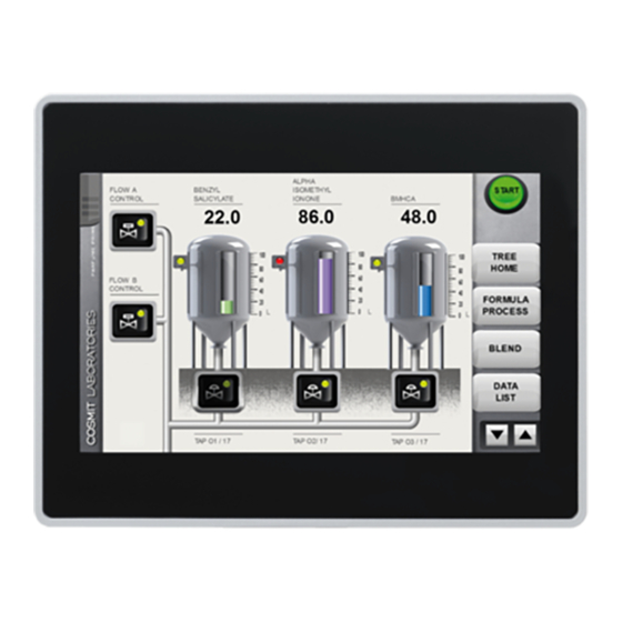
Product overview Product overview The HM500 series programmable displays combine state-of-the-art features and top performance with an oustanding design. They are the ideal choice for all demanding HMI applications including factory and building automation. The HM500 series programmable displays have been designed to run the HMWIN software. -
Page 5: Standards And Approvals
Standards and approvals Standards and approvals The products have been designed for use in an industrial environment in compliance with the 2004/108/EC EMC Directive. The products have been designed in compliance with: EN 61000-6-4 EN 55011 Class A EN 61000-6-2 EN 61000-4-2 EN 61000-4-3 EN 61000-4-4... -
Page 6: Product Identification
Product identification Product identification The product may be identified through a plate attached to the rear cover. You will have to know the type of unit you are using for correct usage of the information contained in the guide. The following information is provided by the plate: ● Product model name ● Product part number ● Month/year of production ● Serial number ●... -
Page 7: Technical Data Common To All Models
Technical data common to all models Technical data common to all models Hardware specifications Touch screen technology Resistive Back-up battery 3V 50mAh Lithium, rechargeable, not user-replaceable, model VL2330. Fuse Automatic Serial Port RS232, RS485, RS422 software configurable User memory • Flash 128Mb for HM504 and HM507 •... -
Page 8: Electromagnetic Compatibility (Emc)
Technical data common to all models Electromagnetic compatibility (EMC) Radiated disturbance test Class A EN 55011 Electrostatic discharge immunity test 8kV (air electrostatic discharge) EN 61000-4-2 4kV (contact electrostatic discharge) Radiated, radio-frequency, 80MHz – 1GHz, 10V/m EN 61000-4-3 electromagnetic field immunity test 1,4GHz – 2GHz, 3V/m 2GHz –... -
Page 9: Technical Data By Model
Technical data by model Technical data by model Model HM504 HM507 Display / Backlight TFT Color / LED Colors Resolution 480x272 800x480 Display size (inch) 4.3” 7” widescreen Dimming Horizontal viewing angle L/R: typ. 50° L/R: typ. 65° Vertical viewing angle U: typ. -
Page 10: Dimensions
Dimensions Dimensions HM504 Cutout Model HM504 149mm 109mm 136mm 96mm 56mm... -
Page 11: Hm507 Hm510 Hm513
Dimensions HM507, HM510, HM513 Cutout Model HM507 187mm 147mm 176mm 136mm 47mm HM510 287mm 232mm 276mm 221mm 56mm HM513 336mm 267mm 326mm 256mm 56mm... -
Page 12: Installation
Installation Installation Installation environment The equipment is not intended for continuous exposure to direct sunlight. This might accelerate the aging process of the front panel film. The equipment is not intended for installation in contact with corrosive chemical compounds. Check the resistance of the front panel film to a specific compound before installation. Do not use tools of any kind (screwdrivers, etc.) to operate the touch screen of the panel. In order to meet the front panel degree of protection if the following requirements are met: •... -
Page 13: Installation Procedure
Installation Installation procedure Place the fixing brackets as shown in the figure below. Make sure to screw each fixing screw until the bezel corner gets in contact with the panel. -
Page 14: Connections
Connections Connections HM504 Serial port 2x Ethernet port USB port Power supply Expansion slot for plug-ins SD card slot HM507, HM510 and HM513 Serial port 2x Ethernet port 2x USB port Power supply 2x Expansion slot for plug-ins SD card slot... -
Page 15: Serial Port
Connections Serial port The serial port is used to communicate with the PLC or with another type of controller. Different electrical standards are available for the signals in the PLC port connector: RS232, RS422, RS485. Use the corresponding communication cable for the connection. The serial port is software programmable. Make sure you select the appropriate interface in the pro- gramming software. -
Page 16: Optional Plug-Ins
Connections Optional plug-ins There are several optional plug-ins available for the HM500 series. Depending on the panel type, there are one or two expansion slots. Slot #2 and slot #4 are available only if the plugin module is equipped with the bus extension connector. -
Page 17: Power Supply, Grounding, And Shielding
Connections Power supply, grounding, and shielding The power supply terminal block is shown in the figure below. +24V Common NOTICE Make sure that the power supply has sufficient power capacity for the operation of the equipment. The unit must always be grounded to earth. Grounding helps limit the effects of noise due to electro- magnetic interference on the control system. Earth connection will have to be done using either the screw or the faston terminal located near the power supply terminal block. A label helps identify the ground connection. Also ground the terminal 3 on the power supply terminal block. -
Page 18: Battery
The equipment must be cleaned only with a soft cloth and neutral soap product. Do not use solvents. 12. Getting started The HM500 series panels must be programmed with the programming software HMWIN Studio, a Windows application. To program a panel you will have to connect the panel via the Ethernet interface to a personal computer running the HMWIN Studio software. -
Page 19: System Settings Tool
System settings tool 13. System settings tool 13.1 Introduction The panels have a system settings tool to allow basic and preliminary settings. The system settings tool comes in the shape of a rotating menu with navigation buttons at the top and the bottom to move between the available options. -
Page 20: Options Available In User Mode
System settings tool 13.2 Options available in user mode User mode is the simplest possible interface, where a generic user can get access to the basic set- tings of the panel: Calibrate touch Allows to calibrate the touch screen interface Network Allows to change the options of the panel on-board network card Time... -
Page 21: Led Indicator On The Front
LED indicator on the front 14. LED indicator on the front The table below shows how the LED indicator works. Symbol Color State Meaning Hardware fault or battery low green Normal operation Flashing Communication error 15. Unpacking and packing instructions To repack the unit, please follow the instructions backwards. -
Page 22: Record Of Changes
• Added information about the viewing angles of the displays • Updated website URL • Updated back page Distributed by Panasonic Electric Works Europe AG https://industry.panasonic.eu/ Copyright © 2011-2021 Exor International S.p.A. – Verona, Italy Subject to change without notice The information contained in this document is provided for informational purposes only. While efforts... - Page 23 Filial Nordic, Knarrarnäsgatan 15, 164 40 Kista, Sweden, Tel. +46 859476680, Fax +46 859476690, www.panasonic-electric-works.se Panasonic Fire & Security Europe AB Jungmansgatan 12, 21119 Malmö, Tel. +46 40 697 7000, Fax +46 40 697 7099, www.panasonic-fi re-security.com Poland Panasonic Industry Poland sp. z o.o.
Need help?
Do you have a question about the HM500 Series and is the answer not in the manual?
Questions and answers