Table of Contents
Advertisement
Quick Links
Advertisement
Table of Contents

Related Manuals for IBC V-10


Summary of Contents for IBC V-10
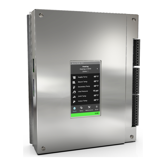
- Page 1 V-10 TOUCHSCREEN CONTROLLER MANUAL VX SERIES...
- Page 2 Handling the touchscreen The touchscreen responds to a light finger touch on the screen. Use only a stylus or a clean finger to interact with the touchscreen. Using sharp or metallic objects will cause damage. If the touchscreen is: Left unattended, the screens will step back one screen at a time in 10-minute intervals. The pop-up windows will also step back automatically in 2-minute intervals.
-
Page 3: Table Of Contents
Contents 1.0 Overview of the controller 1.1 Controller's menu screens 1.2 Who is the manual for? 1.3 Power-up sequence and operational states/cycles 1.4 Getting to know the controller’s interface 1.4.1 Home 1.4.2 Setup 1.4.3 Status 1.4.4 More 2.0 Operating concepts 2.1 Domestic hot water (DHW) 2.1.1 DHW opt out in a multiple boiler network 2.2 Reset heating... - Page 4 5.7 Using the master to control a group of IBC boilers with 5-button-type controllers via a BACnet gateway 5.8 Setting up an IBC air handler to send data to an IBC boiler to control its reset heating curve 6.0 Start-up 6.1 Start-up checklist...
- Page 5 7.0 Optional - Setup for Internet access 7.1 Connecting a boiler’s controller to an IP network 8.0 Updating boiler controller software 8.1 Updating software in a boiler that has no internet access 8.2 Updating software in a boiler that has internet access 9.0 Other operating procedures 9.1 Testing the fan operation 9.2 Testing the firing rate...
- Page 6 Section: Contents 10.3 List of touchscreen controller error messages 10.4 Backing up (exporting) error logs 10.5 Deleting or clearing an error log 10.6 Resetting a boiler after a SIM module ignition lockout 10.7 Resetting a boiler after a LWCO lockout 10.8 Resetting a boiler after a hi-limit temperature lockout 11.0 Definition of terms Appendices...
-
Page 7: Overview Of The Controller
1.0 Overview of the controller The controller provides overall management of boiler operations such as self-diagnostics, easy load parameter adjustments, burner operation, safety management systems, call for heat management and load priority. Figure 1 Touchscreen controller's features * Not applicable to the VX series ** Networking of up to 4 boilers in the VX series... -
Page 8: Controller's Menu Screens
Section: Introduction and overview of the features in the V10 controller 1.1 Controller's menu screens The diagram below shows the controller's four menu options and associated submenus: Figure 2 Map of the controller's menus and submenus... -
Page 9: Who Is The Manual For
1.2 Who is the manual for? 1.2 Who is the manual for? While this manual is primarily written for heating professionals, some of the content may be useful for building managers and homeowners; for example, information about setting overrides. 1.3 Power-up sequence and operational states/cycles When a boiler is first energized, the controller runs through a power-up sequence that takes approximately 90 seconds. -
Page 10: Getting To Know The Controller's Interface
Section: Introduction and overview of the features in the V10 controller 1.4 Getting to know the controller’s interface The controller's main screen displays four menus: Home, Setup, Status, and More. 1.4.1 Home The Home screen displays basic boiler status information such as a title bar with boiler model number and boiler ID as well as its current operating state. -
Page 11: Status
1.4.3 Status 1.4.3 Status The Status menu displays the following options that enable installers to identify problems: Boiler Status Boiler Information Load Status SIM Menu Error Logs Sensor and Channels Clear errors Network Information 1.4.3.1 Boiler Status The Boiler Status screen lists key operational parameters and their current readings. 1.4.3.2 Boiler Information Boiler Information lists basic information such as the controller software version and the boiler model. - Page 12 Section: Introduction and overview of the features in the V10 controller 1.4.3.4 Safety and Ignition Module (SIM) Menu The SIM reports sensor readings and information on the status bar. In the controller's SIM menu, you can: View Status - Provides an overview of the burner, gas valve, ignitor and venting. Perform a Hi-Limit Test - Test the maximum supply cutoff temperature on the boiler.
- Page 13 1.4.3 Status About Status indicators The SIM’s two status LEDs indicate the operating status as shown in the table below. LED 1 LED 2 State Description, LED status indication Rapid Flash Rapid Flash Power up or Startup checks and initialization Resetting Standby LED 1 Off = No Flame or Sparking...
- Page 14 Section: Introduction and overview of the features in the V10 controller System faults. Faults typically related to the touchscreen controller. SIM Status. Operating SIM status errors. See About Status indicators on page On the Error Logs screen, you can: View one or more errors. See Viewing errors on page Clear errors.
-
Page 15: More
1.4.4 More Note that "System" errors do not typically result in a boiler lock-out state. If the controller detects a single "system" error, it will typically continue operation, recording the event in the controller's error log. For more serious "system" errors, or if many system errors occur within a short period of time (about 10 seconds), the controller will treat the event as a major error, or will restart to try to clear the problem. - Page 16 Section: Introduction and overview of the features in the V10 controller 1.4.4.1 User Settings This screen enables the user (installer, homeowner, site manager) to set or adjust: Date & Time - Choose NTP Server or Internal. The controller must be connected to the Internet for the NTP Server selection to work properly.
- Page 17 1.4.4 More 1.4.4.2 Advanced Setup Advanced Setup provides access to the full functionality of the system for the advanced installer. Installers can access and configure the following: Loads 1-4: Assign load types to up to four Loads. For instructions on assigning one or more loads, see Settings loads on page Multiboiler: Set up a boiler to operate as part of a group of boilers (multi-...
- Page 18 IBC boiler for controlling its reset heating curve. See Setting up an IBC air handler to send data to an IBC boiler to control its reset heating curve on page 1.4.4.6 Installer Options For the advanced installer, "Installer Options"...
-
Page 19: Operating Concepts
2.0 Operating concepts This section contains important information about the control strategies used in the controller to deliver space heating, domestic hot water (DHW), pool heating, garage heating, and snow-melting. Depending on heating requirements, strategies will include the use of these control modes: DHW, Reset Heating, Setpoint, Ext. -
Page 20: Reset Heating
When applied to IBC's condensing boilers, the Reset Heating mode enables efficiency benefits by lowering the required circulating water temperature, so that cooler water returns to the boiler (promoting more condensation). -
Page 21: Standard Reset Heating (Default)
°F/0 °C value for the outdoor design temperature, and adopts the appropriate temperature target from the relevant reset curve. IBC's controller offers two reset heating methods for controlling the supply/outlet water temperature: 1. "Standard" reset heating (default) that uses a two-point reset heating ratio. - Page 22 Section: Operating concepts Figure 7 Standard "straight-line" reset heating To determine these two points, and for the system to accurately control the supply/outlet water supply, set the: Design Supply ° – defines the desired boiler outlet water temperature to occur on the coldest day for the building location.
-
Page 23: Advanced Reset Heating
Figure 8 Characterized heating curve in advanced reset heating Fin-tube baseboard IBC Air handler Cast iron radiator Low mass radiant floor High mass radiant floor... -
Page 24: Set Point
Section: Operating concepts To establish or "characterize" a heating curve to an application to deliver a more accurate level of heating, specify the following: Type of emitter - Once the emittter is selected the controller loads the factory defaults. Design Supply ° – the desired boiler outlet temperature to occur on the coldest day. Use this temperature when performing heat loss calculations. -
Page 25: External Control
2.4 External Control The controller's reset mode adjusts the circulating water temperature to maintain a steady and comfortable indoor temperature. Indoor temperature is compared with the preset operating range (set point target), and if the temperature deviates (as sensed by the room thermostat), the controller will bring the temperature back to the set point limits. -
Page 26: Zone Of
Syncing zones with "Zone Of" on page 2.6 Setting load priority Boiler load is the total "work" performed by a boiler. IBC's controller uses a priority algorithm to coordinate or schedule the delivery of heat in multiple load systems. This type of planning strategy temporarily turns off one or more loads based on given conditions in the system. - Page 27 2.6 Setting load priority If using Setup, load priority is simplified with options "very low", "low", "high" or "very high". There's more precision in Advanced Setup, where you can enter numeric values between 20 and 90 for a priority load. Note: The priority value has to be different for each load, but the priority scale values do not need to add up to 100 –...
-
Page 28: Combining Loads
Section: Operating concepts 2.7 Combining loads As a control strategy, load combining is used when two rooms or zones in a building have different temperatures. Running two loads at compatible temperature settings at the same time provides added efficiency and heating comfort. This feature allows two compatible loads to run simultaneously;... -
Page 29: Full Mode Load Combining
2.7.2 Full mode load combining Let’s say a radiant floor is set at 120 °F and an air handler is set at 160 °F. When both load types call for heat, the boiler will supply 160 °F. If only the load for radiant floor is calling, the boiler will supply water temperature at 120 °F. - Page 30 Section: Operating concepts target supply temperature range. The loads will be uncombined if the under temperature condition persists after the Off Delay time. If the supply temperature exceeds the requirements for either the Primary or Secondary loads, the loads will no longer be combined. Retry Delay If the boiler removes the Secondary load from combined service because load combining conditions are not followed, the Retry Delay is the number...
-
Page 31: Setting The Supply Differential In Heating Modes
2.8 Setting the supply differential in heating modes Example of incompatible load combining Primary Load 140 °F to 180 °F Secondary Load 120 °F to 140 °F Initial Delay: 5 mins Off Delay: 5 mins Retry Delay: 10 mins Maximum Throttle %: 75 % The secondary load temperature range of 120 °F to 140 °F is outside the range (does not overlap) with the Primary load's supply temperature range of 140 °F to 180 °F. -
Page 32: Operational Settings In The Setup Menu: Temperature Ranges And Defaults
Section: Operating concepts When you set the differential, check that the Maximum Supply ° is higher then the boiler supply plus half its supply temperature differential to ensure the maximum supply takes account of the construction and safety requirements of each application (e.g., 140 °F/60 °C maximum for typical in-slab radiant floor to avoid thermal stress). - Page 33 2.9 Operational settings in the Setup menu: temperature ranges and defaults Operational settings in the Setup Menu Temp. Mode Setting Description Default Range Reset Emitter Enter the device type used to emit heat: high mass Heating high mass radiant system, low mass radiant radiant system, air handler, cast radiator, or system...
-
Page 34: Operational Settings In The Advanced Setup Menu: Temperature Ranges And Defaults
-76 °F-86 °F 14 °F Outdoor° typically experienced at the installation site. Set the Design Outdoor Air temperature correctly for the geographic location; consult a local IBC wholesaler or the heat loss calculation documentation used in the design of the heating system. - Page 35 2.10 Operational settings in the Advanced Setup menu: temperature ranges and defaults Operational settings in the Advanced Setup Menu Temp. Mode Setting Description Default Range Summer Cut-off level for outdoor temperature that 32 °F-122 °F 65 °F Shutdown° stops further heating Maximum Highest supply water temperature 70 °F-147 °F 70 °F...
- Page 36 Outdoor° typically experienced at the installation site. Set the Design Outdoor Air temperature correctly for the geographic location; consult a local IBC wholesaler or the heat loss calculation documentation used in the design of the heating system. Design This setting only becomes available when 41 °F-95 °F...
- Page 37 2.10 Operational settings in the Advanced Setup menu: temperature ranges and defaults Operational settings in the Advanced Setup Menu Temp. Mode Setting Description Default Range Water Water° From on page Outlet, Sec. From° Loop, DHW Burner On Type of control used to control boiler Thermostat Thermostat From...
- Page 38 Section: Operating concepts Operational settings in the Advanced Setup Menu Temp. Mode Setting Description Default Range Boiler Pump See Boiler Pump on page On-Off Boiler Target temperature for the outlet 95 °F-185 °F 170 °F Supply° Maximum Limit to prevent overheating of supply 41 °F-190 °F 190 °F Supply°...
- Page 39 2.10 Operational settings in the Advanced Setup menu: temperature ranges and defaults Operational settings in the Advanced Setup Menu Temp. Mode Setting Description Default Range Ext. Boiler Pump See Boiler Pump on page On-Off Control Burner On Type of control used to control boiler Thermostat Thermostat From...
- Page 40 Intentionally left empty...
-
Page 41: Wiring
3.0 Wiring Warning Wiring and testing must be performed by experienced and trained professionals. For reference, you can find wiring diagrams for the respective boiler in the Appendices on page 93. This section includes the following topics: Boiler pump Thermostats Load pumps or valves Sensors Alarm contacts... -
Page 42: Thermostats
Section: Wiring Figure 13 : Field wiring box with yellow and white wires for primary pump - VX series 3.2 Thermostats The controller is compatible with most common thermostats including simple single contact types (for example, a mercury switch) as well as most power-stealing-type thermostats. The standard connection for common thermostats provides a simple contact closure for the boiler (see the electrical diagrams in the Appendices on page... -
Page 43: Load Pumps Or Valves
The factory has pre-wired the terminal to use a 120VAC power supply, but it can be configured for other voltage uses in the field. Note that the total loads running should not exceed 10 amps. Note that any pump being directly switched by an IBC control board must draw less than 4 amps. 3.4 Sensors... -
Page 44: Alarm Contacts
Section: Wiring 3.5 Alarm contacts The controller provides a relay dry contact connection to indicate the boiler’s alarm state externally. This can be used, for example, to connect to an external alarm panel or an indicator light. The terminals on TB3 (see Figure 12 ) supply the wiring connection. -
Page 45: Multiple Boilers: Wiring And Networking
(typically for residential scenarios) are generally not suitable for larger multi-boiler applications. You can connect up to 4 IBC boilers in the VX series and up to 24 IBC boilers in the SL G3 series and EX series to operate as a single heating plant. -
Page 46: Internet Connectivity
Section: Wiring 3.7.2 Internet connectivity If you build a network that is not connected to the internet, you can still assign manual IP addresses to each boiler, that is, assign fixed IP addresses. For example, if using the simple 2- boiler networking method, you will need to assign manual IP addresses to both boilers. - Page 47 3.7.4 BoilerNet two-wire CAN bus daisy chain cabling BoilerNet Component Requirements CAN bus interface that The wire type and installation must comply with CAN bus standards communicates between such as ISO 11898 and/or SAE J2284. boilers. Cable Polarity-sensitive twisted 2-wire leads (CAN bus standard) to join one boiler to the next (to a maximum of 24 boilers).
- Page 48 Section: Wiring 3.7.4.1 Removing jumpers when networking three or more boilers When three or more boilers are networked, removal of a circuit board jumper is necessary (as illustrated below). Note on the illustration that you must not remove the jumpers from the boilers on both ends of the networked boiler system.
-
Page 49: Wiring Checklist
Check for poor connection or voltage problems from flickering screens or intermittent calls for heat. □ An Ethernet cable is installed if requiring Internet for connection to the IBC V10 portal. □ Ensure the DHW sensor is fully immersed in the well to prevent tank overheating. - Page 50 Intentionally left empty...
-
Page 51: Settings Loads
Large systems imply significant thermal masses that generally cannot change temperature quickly. The IBC controller can control up to four load pumps that are zoned for the same temperature. However, for multiple-temperature applications, you should use external mixing valves or injection control for cooler demands, or IBC’s "Opt-out"... -
Page 52: Configuring A Load On A Boiler
Section: Settings loads 4.1.1 Configuring a load on a boiler The "Select a load" menu screen appears displaying four possible loads. All loads are set to "Off" to allow the system to be programmed to correspond to the installation’s specific wiring connections. -
Page 53: Syncing Zones With "Zone Of
(see Changing and updating date and time on page 76). Setting the clock is necessary for boilers connected to the IBC V10 portal and for setting overrides. 5. (optional) To change units (Imperial or Metric) on the boiler, go to >... -
Page 54: Removing An Assigned Control Mode From A Load
Section: Settings loads c. Zone Of > tap OK > select the control load that you wish to synchronize the current load with> Save. 4.1.4 Removing an assigned control mode from a load 1. To change a control mode, go to >... -
Page 55: Setting Up An External Control Load
Resetting configured settings to factory defaults on page To set up an IBC air handler to communicate the indoor and outdoor temperatures to enable the boiler to control its reset heating curve, see Setting up an IBC air handler to send data to an IBC boiler to... -
Page 56: Setting Up External Control To Control Water Temperature In A Single Boiler Or In Each Boiler Wired On A Network
The following procedure documents setup required when the external control is modulating the boiler output only for a single boiler operation, or in a multiboiler system where system input from the BMS is wired to each boiler. An IBC network cannot be used. To set up external control: 1. -
Page 57: Combining Two Loads To Service Two Loads At The Same Time
4.5 Combining two loads to service two loads at the same time 4.5 Combining two loads to service two loads at the same time To enable the boiler to service two loads at the same time, you can combine loads using the controller's basic mode or full mode. -
Page 58: Combining Loads Using "Full Mode
Section: Settings loads 4.5.2 Combining loads using "full mode" To combine two loads using " full mode" : 1. Go to > Advanced Setup > Load Combining. The "Basic Mode" box is checked by default. . 2. Uncheck the "Basic Mode" box. More parameters appear on the screen (may need to scroll down): Initial Delay, Off Delay, Retry Delay, and Maximum Throttle. -
Page 59: Configuring Multiple Boiler Systems
5.0 Configuring multiple boiler systems When configuring a network of boilers, you can assign a boiler as the "master" boiler, so that it can control the other "subordinate" boilers on the network. This enables all heating loads to be set up via the master boiler. -
Page 60: Configuring A Subordinate Boiler
Section: Configuring multiple boiler systems 3. In the Master field, tap No > Yes (for Master boiler only – leave all other boilers set to "No"). After assigning a master, the screen populates with these fields: Staging delay, Rotation, Fixed Lead, Firing Order, Add Level (%), Drop Level (%), Opt Out box Types, boilers Online, Boilers Available, Boilers Firing. -
Page 61: Confirming Network Programming Was Successful
5.4 Confirming network programming was successful For information on using the more advanced features such as the "Opt Out" or Failsafe options, scan the QR code at the beginning of this section. 5.4 Confirming network programming was successful After assigning boiler IDs, the controller prompts you to restart. You can check that the master boiler is now the designated master. -
Page 62: Using The Master To Control A Group Of Ibc Boilers With 5-Button-Type Controllers Via A Bacnet Gateway
If you have an IBC air handler connected to one or more IBC boilers, you can set up the air handler to transmit data such as the indoor and outdoor temperatures to enable the boiler to control its reset heating curve. The IBC air handler will transmit these temperatures to any boiler connected to the local area network. -
Page 63: Start-Up
6.0 Start-up Note For a boiler to fire, it needs an "enabler" across the load such as a zone valve end switch, thermostat switch, or jumper. When a boiler is first energized, the controller runs through a power-up sequence that takes approximately one minute. -
Page 64: Testing The Ignition Safety Shutoff
Section: Start-up 6.2 Testing the ignition safety shutoff To test the ignition system safety shutoff device: 1. With the boiler in operation, shut off the gas control valve directly outside the boiler case. 2. Ensure that the boiler has shut off and the appropriate error information is displayed on the controller. - Page 65 6.4 Testing the low water cutoff (LWCO) function To test the LWCO function: 1. Press and hold the LWCO Test button for 5 seconds (located on top of the electrical box). A message on the screen indicates that the boiler is in lockout mode. 2.
- Page 66 Intentionally left empty...
-
Page 67: Optional - Setup For Internet Access
Portal. Figure 19 Benefits of gaining remote access to boilers via the IBC V10 portal To set up remote access to boilers via the V10 portal, you must connect a boiler’s controller to an IP network (see instructions below). Then you can register a boiler for the V10 portal. - Page 68 Section: Optional - Setup for Internet access There are two methods for connecting the boiler to an IP network: 1. Installing an Ethernet cable that connects from the boiler (RJ 45 Ethernet Jack) to the router. 2. Purchasing and installing a wireless access point device connected to the Ethernet jack. The wireless access point device must be configured to operate in client mode (to enable the router to function as a wireless client).
-
Page 69: Updating Boiler Controller Software
Consider updating a boiler with the latest software only if the new features are beneficial to the operation of the boiler. There are two methods for updating software in an IBC boiler: 1. Updating software in a boiler that has no internet access. -
Page 70: Updating Software In A Boiler That Has Internet Access
Section: Updating boiler controller software 8.2 Updating software in a boiler that has internet access At the boiler site, insert the USB flash drive into the boiler controller, and use the menu to complete the software update. When a software update is performed, the touchscreen controller is put into "service"... -
Page 71: Other Operating Procedures
9.0 Other operating procedures This section describes other settings that heating professionals can use when operating, servicing, or troubleshooting a boiler. Testing the fan operation Testing the firing rate Calibrating the fan Performing a manual pump purge Limiting the minimum and maximum firing rate of the boiler Adjusting the space heating temperature Adjusting the domestic hot water temperature Checking the water flow in the boiler... -
Page 72: Testing The Firing Rate
Section: Other operating procedures 3. To check if the heat output value and the fan heat output value correspond, go to > Boiler Status. 9.2 Testing the firing rate You can test the firing rate if the fan is not operating, or if there is a low error flow, low air flow, or low rpm error. -
Page 73: Calibrating The Fan
9.3 Calibrating the fan 9.3 Calibrating the fan After replacing a fan or performing a software update, fan calibration is required. 1. Remove all calls for heat by pulling out the entire TB2 terminal block (see Figure 12 2. Go to >... -
Page 74: Adjusting The Space Heating Temperature
Section: Other operating procedures 2. (If applicable) Tap System Options > Tap the number value in the Minimum Output field and enter a higher minimum output (e.g., if the minimum output is currently 10, enter 15) > OK > Save. 3. - Page 75 9.9 Setting overrides You can set up overrides for a set point load in a boiler. For example, building managers may want to set up overrides in the system so that domestic hot water is set up to heat the water to 140° C at night to kill bacteria in the water.
-
Page 76: Backing Up And Restoring A Boiler's Configuration And Settings
Section: Other operating procedures 9.10 Backing up and restoring a boiler's configuration and settings You can back up/restore a boiler’s complete controller configuration and settings to or from a USB memory stick or SD-card that you can then load onto other boilers. This saves time when setting up multiple boilers that will have the same configuration and settings. -
Page 77: Restricting Access To Areas In A Controller
9.11 Restricting access to areas in a controller 9.11 Restricting access to areas in a controller In the controller, you can restrict access to the boiler controls by enabling password access. When you enable password protection, you are provided with an installer default password and a user default password. -
Page 78: Changing And Updating Date And Time
IBC V10 portal. You can also manually change the factory default time (e.g., different time zone). 9.14.1 Setting up date and time to update automatically in a boiler connected to the Internet If the boiler is connected to the Internet or to a computer (e.g., a server set up on an internal... -
Page 79: Changing Default Error Lockout Time Periods
9.15 Changing default error lockout time periods To set the date and time manually: 1. Go to > User Settings > Date & Time. 2. Ensure that the Internal option (default) is selected. "Internal" refers to an internal clock used for time keeping. -
Page 80: Programming A Replacement Touchscreen Controller
2. Tap the Save button. Note Do not select the “Start” button to run the Self Test. This is for IBC staff use only. 3. Select "Setup" to set up the loads configured in the old boiler. 4. Check that the boiler has registered the thermostat connections correctly along with the correct load types and settings. -
Page 81: Troubleshooting
10.0 Troubleshooting This section provides a list of controller error messages and possible way to resolve the errors. For information on the types of errors, see Clear Errors on page 12. Note that disconnected wires or defective sensors may be the cause of the error. Always check connections and wiring first. Warning Do not attempt to repair the control module (circuit board). - Page 82 Section: Troubleshooting Diagnosis & Recommended Error Text Troubleshooting Ign. Trials Exceeded No spark when igniting. Ignitor probe/flame sensor disconnected, dirty, or old. Touch Screen Message: Check that ignitor lead is secure at the control module and at the probe. Error – Ignition Failure after 3 tries Boiler has failed to ignite on 3 successive attempts.
- Page 83 10.0 Troubleshooting Diagnosis & Recommended Error Text Troubleshooting vessel/ burner or unserviceable ignition lead or spark module. Ensure the pressure vessel is grounded. Check the igniter probe/flame sensor is electrically isolated from the vessel, and its ceramic insulator is intact. Replace ignition lead Replace spark module Vent Pressure...
- Page 84 Section: Troubleshooting Diagnosis & Recommended Error Text Troubleshooting Low Air Flow Check the flame signal at low fire. If the flame signal is low then: Other message that may display Check the low fire tuning. See the table simultaneously: Flame Sig/Vent Blk. for Low Fire in the Commissioning section for each boiler model.
- Page 85 10.0 Troubleshooting Diagnosis & Recommended Error Text Troubleshooting Inlet Pres. Sensor Check that the Inlet Pressure Sensor is connected properly. It may need replacing. Check the connector on the back of the circuit board. Other message that may display: Inlet Pres. Sensor.
- Page 86 Section: Troubleshooting Diagnosis & Recommended Error Text Troubleshooting Output Limited (warning) - indicates that the Warning may appear if: boiler is limiting/reducing water temperature and/or vent temperature output. The Inlet/Outlet water temperature differential exceeds the maximum allowed. The inlet water temperature is very close to the max.
-
Page 87: Backing Up (Exporting) Error Logs
10.4 Backing up (exporting) error logs 10.4 Backing up (exporting) error logs You may need to back up an error log onto a USB stick to send to IBC's Technical Support team for troubleshooting. 1. To back up an error log, go to >... -
Page 88: Resetting A Boiler After A Hi-Limit Temperature Lockout
Section: Troubleshooting 5. If the error persists, test the LWCO. Go to > SIM Menu> LWCO Test > Run the test to check if the low water cutoff sensor is opening. 10.8 Resetting a boiler after a hi-limit temperature lockout A boiler that has been placed in a lockout condition due to a hi-limit temperature error will need to be reset in the controller's SIM module. -
Page 89: Definition Of Terms
11.0 Definition of terms 11.0 Definition of terms Term Definition Add Level Sets the relative ouput level at which an idle boiler fires up. This is a percent of the maximum firing rate of the lead boiler – on a 40-399 G3, for instance, a value of 60 would correspond to an output of 399 x 60/100 = 239. - Page 90 BoilerNet connection, coordinate mode firing of all subordinate boilers. This fully autonomous approach uses IBC’s internal heat regulation and boiler management software. Group Add Similar to Add Level (%) for master boilers, this is the relative output level at which the Level (%) Group Opt Out Lead will bring another boiler on to service the Group Opt Out load.
- Page 91 Not connected NTP Server Network Time Protocol Opt out A term used by IBC to describe a boiler that "opts out"or becomes unavailable to a network to satisfy a request. Typically, opt out boilers are used and dedicated to service DHW.
- Page 92 Section: Definition of terms Term Definition Opt out types The Opt Out Type for each load dictates how the load is handled by the multi-boiler Load 1-4 algorithm. None: Only for boilers configured as a master. This load is serviced by the entire multi-boiler network (the master will not opt out to service the load, but will use all boilers to service it).
- Page 93 This signal corresponds to a target set-point temperature, with the range scaled mode according to the programmed min-max temperatures. IBC’s multi-boiler heat regulation algorithm still determines which boiler fires, throttle levels etc., but to an externally determined operating temperature. Call-for-heat to the Master can be conveyed via a 2.1+ VDC signal on the External Control terminal, or via a dry contact boiler enable...
- Page 94 Section: Definition of terms Term Definition Staging The number of minutes between boilers being fired up or shut down by the master, that Delay is, the length of time before the next boiler is brought online once the current firing boiler has passed its add boiler firing rate level.
-
Page 95: Appendices
Appendices Appendices This section includes the controller board diagram, internal wiring diagram, Opt out DHW wiring diagram, and sequence of operation. Controller Board Layout Figure 20 Front and back of controller... -
Page 96: Internal Wiring Diagram Vx Series Boilers
Section: Appendices Internal wiring diagram VX series boilers Figure 21 VX series - internal diagram... -
Page 97: Wiring Diagram - Opt Out Dhw
Wiring diagram - Opt Out DHW Wiring diagram - Opt Out DHW Figure 22 Opt Out DHW wiring diagram... -
Page 98: Sequence Of Operation - Vx Series Boilers
Section: Appendices Sequence of Operation - VX series boilers Figure 23 VX series - Sequence of Operation... -
Page 99: Index
Index minor 11 Checking water flow 72 SIM Status 12 clean the screen 14 adjusting states 12 Clear errors air in boiler 71 system faults 12 about error states 12 domestic hot water Error logs 11 temperature 72 Combining loads backing up space heating (exporting) 85... - Page 100 57 Reset heating curve load 28 configuring subordinate full mode 27 sending air handler data boilers 58 to IBC boiler to incompatible load confirming boilers control reset combining 29 available in heating curve 60 network 59 setting two loads in basic...
- Page 101 multiboiler - removing Setting loads 49 Switching a boiler to jumpers 46 unoccupied mode 75 setting up multiple boiler multiboiler networking system 57 System settings 15 with Ethernet switch 44 Setup multiple boilers and V10 Internet Portal Test Operation 15 networking 43 registration 65 sensors 41...
- Page 103 856-735-5584 Toll Free: 1-844-HEAT-IBC/ 1-844-432-8422 www.ibcboiler.com Information in this document is subject to change without notice. IBC assumes no responsibility for changes made to the manual due to clerical errors, to regulation changes, or to product development. April, 2021 120-330E1 ©...
Need help?
Do you have a question about the V-10 and is the answer not in the manual?
Questions and answers