
Related Manuals for IBC V-10


Summary of Contents for IBC V-10
- Page 1 V-10 TOUCH SCREEN BOILER CONTROLLER This Manual is also available in French - contact IBC or visit our web site www.ibcboiler.com www.ibcboiler.com...
-
Page 3: Table Of Contents
1.0 IBC MODEL V10 TOUCH SCREEN CONTROLLER ........1... -
Page 5: Ibc Model V10 Touch Screen Controller
Load Combining – simultaneous operation of 2 similar water temperature loads • The control can manage and/or operate in a network of up to 24 IBC VFC or SL boilers Some of the new features available in the touch screen control include: •... -
Page 6: Control Interface
V-10 TOUCH SCREEN BOILER CONTROLLER Operational and historical data may be accessed at any time using the System Status and Load Profiles sections of the control. Error logs are available in the Diagnostics section and the controller is capable of recording any or all errors since original power-up complete with the date and time of the error. -
Page 7: Navigation Overview
V-10 TOUCH SCREEN BOILER CONTROLLER 1.3.2 Navigation Overview Navigating through the controller touch screen interface is designed to be simple, consistent and intuitive. There are three screen types; Menu Screens, Status Display Screens and Setting Screens. The display can be split in some cases to show a Menu Screen and a Setting Screen at the same time. -
Page 8: Password Pop-Up Window
V-10 TOUCH SCREEN BOILER CONTROLLER 1.3.2.4 PASSWORD POP-UP WINDOW Access to setup areas that allow operational parameters to be changed can be restricted by requiring a password to be entered. If the Security mode is on then the password pop-up window with will appear as soon as a button is pressed that provides access to a restricted area. -
Page 9: Home Screen
V-10 TOUCH SCREEN BOILER CONTROLLER HOME SCREEN The Home Screen displays basic boiler status information. The title bar shows the boiler model number and boiler ID number if set higher than zero. Just below the title bar a line of bold text indicates the current operating state and immediately below that the load currently being serviced, if any, is displayed. -
Page 10: Express Setup
Reset Heating is to be used for any of the loads. This temperature is available from a number of sources including the local IBC wholesaler. The Design Outdoor Air Temperature can also be found in the heat loss calculation documentation used in the design of the heating system. -
Page 11: Load Status
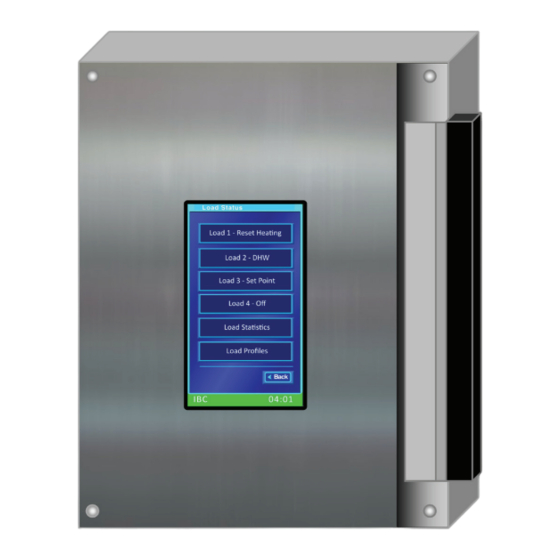
V-10 TOUCH SCREEN BOILER CONTROLLER The Express – Loads screen displays a selection button for each of the 4 possible loads. All loads are set to OFF from the factory allowing the system to be programmed to correspond to the installation’s specific wiring connections. If Load 1 has been piped and wired - (Load 1 = P/V1 &... -
Page 12: Installer Settings
V-10 TOUCH SCREEN BOILER CONTROLLER The Overrides screen allows the override programming for each load to be enabled or disabled and by touching the Edit button the override temperatures with corresponding start and end times can be set for each load by day of the week. - Page 13 V-10 TOUCH SCREEN BOILER CONTROLLER Depending on the settings it’s possible for the indoor temperature to overshoot the desired indoor temperature. Reducing the Ramp Speed Value will help reduce this overshooting issue. The factory Ramp Speed setting is Auto. While set to Auto the controller uses the selected heat emitter type to automatically determine an appropriate ramp speed.
-
Page 14: System Settings
V-10 TOUCH SCREEN BOILER CONTROLLER Burner On From – This feature is found on a load set to External Control. The setting can be Therm. or Ext. Control so that the load will respond to a call for heat from either the Thermostat or External Control. If set as Therm. then the boiler will wait for a call for heat on the Thermostat terminal associated with the load and then look at the Ext. - Page 15 V-10 TOUCH SCREEN BOILER CONTROLLER The Error Log screen title bar shows “Error Log: (record no) (total no. of error records)”. If there are no error records logged the title bar will show “Error Log: 1/0” and the Date will be shown as End of Log. An error record screen for an actual error event will have a View button beside the type of error.
-
Page 16: Sequence Of Operation
V-10 TOUCH SCREEN BOILER CONTROLLER The Advanced Display status screen lists 17 key operational parameters and their current readings. Password protected, for use by IBC personnel. Allows the Controller software to be updated via an SD memory card or USB memory stick. -
Page 17: Standby
V-10 TOUCH SCREEN BOILER CONTROLLER 1.6.1 Standby Waiting for a Heating Enabled signal (as defined in the above glossary), the burner and boiler pump are off during this time. 1.6.2 Purging PREPURGE On a Heating Enabled signal, the boiler automatically enters a prepurge cycle. -
Page 18: Heating
V-10 TOUCH SCREEN BOILER CONTROLLER 1.6.4 - Heating The heating cycle lasts until the Heating Enabled state ends (for all loads) or until water temperature exceeds the target temperature by 1/2 of the supply differential for the last served load and the throttle has fallen to the minimum output. -
Page 19: Error Mode
V-10 TOUCH SCREEN BOILER CONTROLLER 1.6.6 Error Code The controller continually checks sensors to see that they are operating within normal parameters. If sensors indicate the boiler is operating outside it limits, it will declare an error condition. Two types of error conditions can occur: •... -
Page 20: Load Combining
V-10 TOUCH SCREEN BOILER CONTROLLER Heat-apportioning can be altered in the Installer Settings input section. For instance if Baseboards (set up with Outdoor Reset as Load 3) are not providing the desired heat, the on-time of the baseboards can be increased by increasing the Priority value relative to the other declared channels (e.g. -
Page 21: Considerations For Combining Loads
So it is possible that as outdoor and/or indoor temperatures change, reset and external control heating loads could drift in and out of compatibility for Load Combining. See IBC Technical Note: Load Combining for further details. -
Page 22: Reset Heating
V-10 TOUCH SCREEN BOILER CONTROLLER 1.7.3 - Reset Heating The boiler offers Reset Heating or outdoor reset control as standard equipment; this feature coordinates the control of boiler supply/outlet water temperature for space heating with the outdoor temperature. Reset Heating offers enhanced... -
Page 23: Temperature Differential Settings
V-10 TOUCH SCREEN BOILER CONTROLLER Heating settings screen. To increase heat (e.g. From 72°F/22°C to 74°/23°C) - move the Indoor Setpoint ° value upward (warmer) from the level otherwise chosen. This shifts the position of the reset curve, will amend the boiler water temperature by a similar amount. -
Page 24: Unoccupied Mode
V-10 TOUCH SCREEN BOILER CONTROLLER For Reset Heating loads the Indoor Setpoint temperature setting will be overridden for the programmed time periods. For Set Point loads the Boiler Supply temperature setting will be overridden and for DHW loads the DHW Tank Setpoint will be overridden. -
Page 25: External Control
Error Log and will be displayed in the boiler status bar. 1.7.10 Multi-Boiler Operation NOTE The Multi-Boiler capability allows a group of up to 24 IBC boilers to be Consult IBC’s latest technical connected and networked together to operate as a single heating plant. The... -
Page 26: Internet Networking
JA02 must be left installed in both controllers and in a three boiler network the JA02 must be removed on the middle boiler only. Please contact IBC if any additional information is required. 1.7.11 Internet Networking Internet Protocol (IP) networking based features are supported via the standard RJ 45 Ethernet jack on the back of the controller board. -
Page 27: Web Browser Interface
V-10 TOUCH SCREEN BOILER CONTROLLER 1.7.12 Web Browser Interface The IBC V-10 controller includes built in web pages to support a complete user interface via a standard web browser. All the settings, status information and control capabilities available on the touch screen are also available via the web browser interface. -
Page 28: Diagrams
V-10 TOUCH SCREEN BOILER CONTROLLER DIAGRAMS ELECTRICAL WIRING DIAGRAM OPERATING INSTRUCTIONS... - Page 29 V-10 TOUCH SCREEN BOILER CONTROLLER 2.1.1 Thermostat Connections The controller is designed to be compatible with most common thermostats including simple single contact (mercury switch) types as well as most power stealing type thermostats. The standard connection for common thermostats that provide a simple contact closer for the boiler is shown in the Electrical Ladder Diagram on the previous page.
-
Page 30: Internal Wiring Diagram
V-10 TOUCH SCREEN BOILER CONTROLLER INTERNAL WIRING DIAGRAM INTERNAL WIRING DIAGRAM Better Boilers brown Combustion Valve blue blue 5 x plug blue blue orange green orange Transformer blue blue brown black Vent High black black Limit orange Switch Upper Vessel... -
Page 31: Controller Board Layout
V-10 TOUCH SCREEN BOILER CONTROLLER CONTROLLER BOARD LAYOUT NOTE See Instruction Sheet # for instructions on installing a V-10 Touch Screen Boiler Controller. Re-Order Part #500-044. OPERATING INSTRUCTIONS... -
Page 32: Sequence Of Operation
V-10 TOUCH SCREEN BOILER CONTROLLER SEQUENCE OF OPERATION OPERATING INSTRUCTIONS... - Page 33 NOTES...
- Page 34 NOTES...
- Page 35 REVISION HISTORY R1 (JULY 2014) Initial release R2 (JULY 2015) Address update...
- Page 36 IBC Technologies Inc. 8015 North Fraser Way Burnaby, BC Canada V5J 5M8 Tel: 604.877.0277 Fax: 604.877.0295 www.ibcboiler.com 120-198-R2 July 2015 © IBC Technologies Inc. 2015...
Need help?
Do you have a question about the V-10 and is the answer not in the manual?
Questions and answers