Advertisement
Installation Guide for Beam LTE Marine Bundle
(MG200-MB5 / MG200-MB10)
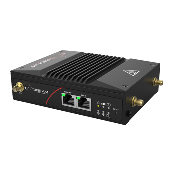
Beam MG200 LTE Gateway
Package Contents
1 x Beam MG200 LTE Gateway Kit
5m
1 x Beam LTE931 5m Cable
(MG200-MB5 only)
Optimal Antenna Installation Location
o
• 360
clear view of the horizon
• Highest possible point
• Away from other transmitting devices
• Securely installed
Applications
LARGE VESSELS
For more information please visit: beamcommunications.com/cellular
Beam LTE931 5m Cable
(MG200-MB5 only)
Beam LTE933 10m Cable
SMA
(MG200-MB10 only)
Lightning
Arrestor
(not included)
1 x Beam LTE710 Stick Antenna
10m
OR
1 x Beam LTE933 10m Cable
(MG200-MB10 only)
• Installed with a separation distance of at least 20cm
• Away from heat or fumes
• Covered under the lightning rod
• Not in the beam path of RADAR, regardless of distance
LEISURE CRAFT
Beam LTE710 Stick Antenna
OR
N-Type
1 x LTE141 Mast/Rail Mount Bracket Kit
1 x Installation Guide
from all persons
Advertisement
Table of Contents

Related Manuals for Beam MG200-MB5


Summary of Contents for Beam MG200-MB5
- Page 1 • Away from other transmitting devices • Away from heat or fumes • Securely installed • Covered under the lightning rod • Not in the beam path of RADAR, regardless of distance Applications LARGE VESSELS LEISURE CRAFT For more information please visit: beamcommunications.com/cellular...
- Page 2 Antenna Installation 1. Install the LTE141 Mast/Rail Mount Bracket on a vertical mast or horizontal rail (Ø 10 - 30 mm). Then mount the antenna. WARNING! For lightning protection, the mast or rail shall be connected to the common ground of the boat. Vertical Mast Mount Horizontal Rail Mount Assembly...
Need help?
Do you have a question about the MG200-MB5 and is the answer not in the manual?
Questions and answers