
Related Manuals for Huawei F01T500


Summary of Contents for Huawei F01T500
- Page 1 F01T500 Quick Installation Guide Issue: 07 Date: 2017-05-03 HUAWEI TECHNOLOGIES CO., LTD.
- Page 2 About This Document Intended Audience This topic describes how to install the F01T500 cabinet, including installing the cabinet, routing cables, and powering on the system. The intended audience is hardware installation engineers. Symbol Conventions The symbols that may be found in this document are defined as follows.
- Page 3 Updates in Issue 06 (2017-03-01) Based on issue 05 (2016-09-01), this document is updated as follows: Added the AC+RPR power supply. Updates in Issue 05 (2016-09-01) Based on issue 04 (2016-05-30), this document is updated as follows : Added the description of installing a power meter box for a cabinet . Added the description of installing a cabinet on an underground base.
-
Page 4: Table Of Contents
Contents 1 Precautions …………….…………………………………………......………….1 2 Tools for Installation ………………………………………......………………….2 3 Appearance and Structure ………………………………………......…………….3 4 Installing the Cabinet on a Concrete Pedestal…………......…………….8 4.1 Construct the Concrete Pedestal ………………………………………………………….8 4.2 Fastening the Cabinet ….………..............12 5 Installing the Cabinet on an Underground Base…………….......………..23 5.1 Appearance of the Underground Base...... - Page 5 8 Installing Batteries (AC Power Supply) ………………………………………..………………….67 8.1 Installation Requirements ……………………..……………………………………………….67 8.2 Pre-installation Check..………..................68 8.3 Connecting Batteries..………...................69 10 Checking the Cabinet Installation …………………….……....………….73 11 Powering On the Device (AC Power Supply) )……....…………………74 1 2 P o w e r i n g O n t h e D e v i c e ( R P S P o w e r S u p p l y ) … … … … … … ..… . 7 5 13 Powering On the Device (AC+...
-
Page 6: Precautions
(Note: Do not tear the own packages of the desiccant). Then, put the desiccant packages at proper places of the cabinet. After powering on the cabinet, the desiccant packages must be removed and disposed of as an industrial waste. Copyright © Huawei Technologies Co., Ltd. 2015 All rights reserved. -
Page 7: Tools For Installation
2 Tools and Meters Before you begin, get the following tools ready. Wire stripper Flat-head screwdriver Phillips screwdriver Diagonal pliers Measuring tape Claw hammer Adjustable wrench Socket wrench Hammer drill Impact tool Hydraulic crimper Cable cutter ESD wrist strap Network cable Multimeter ESD gloves crimping pliers... -
Page 8: Appearance And Structure
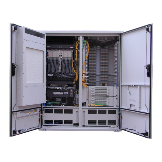
3 Appearance and Structure Cabinet outline Unit: mm With battery cabinet Without battery cabinet With power meter box 346.5... - Page 9 3 Appearance and Structure Cabinet structure (AC Power Supply) Battery compartment Cable distribution Internal-circulation Fan (Optional) compartment Service device AC PDU External- Battery Circulation fan Battery Heater Power system CCU (or Fan monitoring box + signal transferbox) Meter installation position Circuit breakers installation position Power meter box Fuse interface...
-
Page 10: 2 P O W E R I N G O N T H E D E V I C E ( R P S P O W E R S U P P L
3 Appearance and Structure Cabinet structure (RPS Power Supply) Internal-circulation Fan Cable distribution compartment Service device Protective cover of the RPS terminal block External- circulation fan DC PDU Cabinet structure (AC+RPR Power Supply) Internal-circulation Fan Cable distribution compartment Service device Protective cover of the RPS terminal block External-... - Page 11 3 Appearance and Structure Dimensions of installation interfaces Unit:mm (Top view) Front door side of the cabinet Bottom of battery department Front door side of the cabinet Cable area for power cable, optical cable(Upstream), and Inner installation holes 4-Ø18 PGND cable Outer installation holes 4-Ø18 Cable area for subscriber cable or optical cable(Downstream) Square holes...
-
Page 12: 4 S E A L I N G T H E C A B I N E
3 Appearance and Structure Left side of the cabinet Cable hole for power cable and PGND cable Cable trough installation holes 2-M6 Power meter box installation holes 4-M6... -
Page 13: Installing The Cabinet On A Concrete Pedestal
According to the actual requirements, install the cabinet with the outer installation holes or the inner installation holes. Square holes must be reserved on the concrete ground for easy cable routing. Plan space for the concrete pedestal F01T500 cabinet Unit: mm Ground... - Page 14 4 Installing the Cabinet on a Concrete Pedestal With battery cabinet Unit: mm Installation position for the battery cabinet Ground Top view Square holes Installation position for the battery cabinet Cable area for subscriber cable or optical cable Cable area for power cable, optical (Downstream) cable(Upstream), and PGND cable Outer installation hole...
- Page 15 4 Installing the Cabinet on a Concrete Pedestal With power meter box Unit: mm Ground 14 mm Rebar Top view Square holes Cable area for subscriber cable or optical cable Cable area for power cable, optical (Downstream) cable(Upstream), and PGND cable Outer installation hole Inner installation hole...
- Page 16 4 Installing the Cabinet on a Concrete Pedestal Construct the concrete pedestal. Decide the specific method for constructing the concrete pedestal based on the • local standards. Ensure the constructed concrete pedestal is horizontal.The horizontal deviation must be within 4 mm. Cover the sealing material (such as silica gel and grease) onto the cable hole at the bottom of the cabinet to seal the •...
-
Page 17: Fastening The Cabinet
The accessories of a battery compartment include 3 types of spacers. These 3 types of spacers have different • thicknesses. Select a proper spacer based on the live-network environment so that the cabinet bottom is level. F01T500 cabinet Bearing capacity of the steel rope > 750kg... - Page 18 4 Installing the Cabinet on a Concrete Pedestal You are advised to use a socket handle (recommended length: 100 mm) on the socket for screw tightening. • Fastening the Cabinet with the Inner Installation Holes Unit:mm...
- Page 19 4 Installing the Cabinet on a Concrete Pedestal With battery cabinet...
- Page 20 4 Installing the Cabinet on a Concrete Pedestal Connecting kit 1 Connecting kit 2 Put away the removed nylon nuts, among which, 3 are used to fasten the cable-through ring. • Mechanical parts for Nylon nuts Outer side of the Inner side of the Cable through the oil engine port...
- Page 21 4 Installing the Cabinet on a Concrete Pedestal Prevent the battery cabinet from falling when hoisting it.. • The accessories of a battery cabinet include 3 types of spacers. These 3 types of spacers have different thicknesses. • You need to select suitable spacers based on the live network conditions to adjust the steps between cabinets that are installed side by side.
- Page 22 4 Installing the Cabinet on a Concrete Pedestal Fastening the Cabinet with the Outer Installation Fastening the Cabinet with the Inner Installation Holes You are advised to use a socket handle (recommended length: 100 mm) on the socket for screw tightening. •...
- Page 23 4 Installing the Cabinet on a Concrete Pedestal Unit:mm...
- Page 24 4 Installing the Cabinet on a Concrete Pedestal With power meter box Remove the plastic fillers from the • side panel of the cabinet, install the supports of the cable trough. Unit:mm Cable trough support Plastic fillers...
- Page 25 4 Installing the Cabinet on a Concrete Pedestal...
- Page 26 4 Installing the Cabinet on a Concrete Pedestal Use the M6 screw to fix the power meter box to the side panel of the cabinet. • Use the M4 screw to fix the power meter box to the cable trough. •...
- Page 27 4 Installing the Cabinet on a Concrete Pedestal...
-
Page 28: Installing The Cabinet On An Underground Base
5 Installing the Cabinet on an Underground Base 5.1 Appearance of the Underground Base Dimensions of the Underground Base Unit:mm Top view Installation holes 4-M12... -
Page 29: Digging A Foundation Pit
5 Installing the Cabinet on an Underground Base 5.2 Digging a Foundation Pit NOTICE Select a site based on the following principles: avoid places with unfavorable soil, such as collapsible loess, frozen soil, • muddy soil, and quicksand; keep the site far from places such as landfills, backfilled ponds, slopes, retaining walls, and sewers;... -
Page 30: Laying The Underground Base
5 Installing the Cabinet on an Underground Base 5.3 Laying the Underground Base NOTICE The underground base is heavy. This process requires multiple-person collaboration. Protect the underground base from • damage. Any crack or exposure of glass fiber on the post or panel caused by tool collisions is not allowed. The pre-buried cables (or pipes) must rise slightly above the ground. -
Page 31: Filling Soil Back To The Foundation Pit
5 Installing the Cabinet on an Underground Base 5.4 Filling Soil Back to the Foundation Pit NOTICE Do not use waste soil (such as soil containing gravels, construction wastes, or weeds) to back fill the pit. During the • backfilling, tramp down the soil. After the backfilling, ensure that the soil surface does not sink when a person of 80 kg stands on it. - Page 32 H1:height difference between the surface of back filled soil inside the base and the ground, H1 > 0 mm. H2: height difference between the surface of back filled soil outside the base and the ground, 50 mm < H2 < 100 mm. H3: height difference between the bottom of the pit and the ground, 670 mm <...
-
Page 33: Installing The Cabinet On The Underground Base
The accessories of a battery compartment include 3 types of spacers. These 3 types of spacers have different • thicknesses. Select a proper spacer based on the live-network environment so that the cabinet bottom is level. F01T500 cabinet Place the cabinet on the underground base. Bearing capacity of the steel rope > 750kg... - Page 34 Remove the 4 black plastic covers at the bottom of Remove the four mounting feet of the cabinet. the battery compartment, then use 4 screws to fasten the cabinet, and then install the 4 black plastic covers back. Apply sealing materials (such as silica gel and Fence the cabient after it is installed.
- Page 35 With power meter box Seal the gap between the power meter box and the cabinet, and seal the cable holes of the cabinet to prevent vapor from • entering the cabinet. See the meter manual to connect a power meter. •...
- Page 36 Install the power meter box. Seal the power meter box. Fence the cabient after it is installed.
-
Page 37: Routing Cables
6 Routing Cables 6.1 Routing the Cabinet PGND Cable Ensure that the cabinet is grounded properly, and the cabinet is safe and reliable; in addition, it is recommended to install • an electrical leakage protective device on the power supply side of the site to protect personnel against the injury caused by the accidental electric shock on the device side. - Page 38 With power meter box...
-
Page 39: Connecting Power Cables(Ac Power Supply)
6 Routing Cables 6.2 Connecting Power Cables(AC Power Supply) An all-polarity disconnection device is installed on the power supply side of the site. Shut off the AC input, and attach • labels on the switches that will be set during the cabling work. Insulate the AC terminals and all unnecessary bare parts. - Page 40 With power meter box AC power cables AC power cables...
-
Page 41: Connecting Power Cables(Rps Power Supply)
6 Routing Cables 6.3 Connecting Power Cables(RPS Power Supply) NOTICE Power off the central office (CO) RPS before connecting the RPS power cable, and power on the CO RPS after • cable connection. After the external copper cable is routed from the RPS into the cabinet, connect the ground cable to the ground •... - Page 42 6 Routing Cables 6.3 Connecting Power Cables(RPS Power Supply) Loose captive screws to remove the cover. Use fiber patch cords to connect exchange side terminal blocks and cable side terminal blocks. For details about the connections, see “Diagram of Cable Connections Between the RPS and MDF”.
- Page 43 6 Routing Cables 6.3 Connecting Power Cables(RPS Power Supply) Use the impact tool to wire the wires from the external copper cable into the exchange side terminal blocks on the cord patching side according to ”Diagram of Cable Connections Between the RPS and MDF”. (The following figure uses 2- to-1 wire pair connection as an example.
-
Page 44: Diagram Of Cable Connections Between The Rps And Mdf (Rps Power Supply)
6 Routing Cables 6.3 Diagram of Cable Connections Between the RPS and MDF (RPS Power Supply) -
Page 45: Installing The Ac+ Rpr Power Module
6 Routing Cables 6.5 Installing the AC+RPR Power Module Power off the central office (CO) RPS before connecting the RPS power cable, and power on the CO RPS after cable • connection. After routing external user cables into the cabinet, reserve an extra length so as to clamp the cables to the cable side •... -
Page 46: Connecting Power Cables(Ac+Rpr Power Supply)
6 Routing Cables 6.6 Connecting Power Cables(AC+RPR Power Supply) NOTICE Power off the central office (CO) RPS before connecting the RPS power cable, and power on the CO RPS after • cable connection. After the external copper cable is routed from the RPS into the cabinet, connect the ground cable to the ground •... - Page 47 6 Routing Cables 6.6 Connecting Power Cables(AC+RPR Power Supply) Loose captive screws to remove the cover. Use fiber patch cords to connect exchange side terminal blocks and cable side terminal blocks. For details about the connections, see “Diagram of Cable Connections Between the RPS and MDF”.
- Page 48 6 Routing Cables 6.6 Connecting Power Cables(AC+RPR Power Supply) Use the impact tool to wire the wires from the external copper cable into the exchange side terminal blocks on the cord patching side according to ”Diagram of Cable Connections Between the RPS and MDF”. (The following figure uses 2- to-1 wire pair connection as an example.
-
Page 49: Diagram Of Cable Connections Between The Rps And Mdf (Ac+ Rpr Power Supply)
6 Routing Cables 6.7 Diagram of Cable Connections Between the RPS and MDF (AC+RPR Power Supply) - Page 50 6 Routing Cables 6.6 Connecting Power Cables(AC+RPR Power Supply) An all-polarity disconnection device is installed on the power supply side of the site. Shut off the AC input, and attach • labels on the switches that will be set during the cabling work. Insulate the AC terminals and all unnecessary bare parts.
- Page 51 6 Routing Cables Route the input Cables of the AC+RPR power supply...
- Page 52 6 Routing Cables Connect the monitor cable of the AC+RPR power supply Cable connections when the signal transfer box is used for monitoring Cable connections when the CCU is used for monitoring...
-
Page 53: Connecting External Subscriber Cables
6 Routing Cables 6.8 Connecting External Subscriber Cables(Copper Configuration or Optical/Copper Mixed Configuration) After routing external user cables into the cabinet, reserve an extra length so as to clamp the cables to the cable side • terminal block on the MDF. Scenario where fiber patching is required (such as, narrowband-access-only scenario) Cable side terminal block Shielded cable ground... - Page 54 6 Routing Cables Scenario where fiber patching is not required (such as, broadband-access-only scenario) Cable side terminal block Shielded cable ground point (optional) Impact tool Protective unit...
-
Page 55: Connecting Optical Cable And Optical Fibers (Upstream)
6 Routing Cables 6.9 Connecting Optical Cable and Optical Fibers (Upstream) Do not look into the optical port without eye protection. You must use protection pipe to protect core wires of optical cables in the cabinet, and use the binding strap to bind •... -
Page 56: Connecting Optical Cable And Optical Fibers
6 Routing Cables 6.10 Connecting Optical Cable and Optical Fibers (Downstream, Optical Configuration) Do not look into the optical port without eye protection. You must use protection pipe to protect core wires of optical cables in the cabinet, and use the binding strap to bind •... - Page 57 6 Routing Cables With adapters on the middle panel Reinforcing core Shielded cable wiring terminal Protection pipe Hose clamp Optical cable Protection pipe All fibers must be routed over the cable manager so that the cabinet door will not be hindered by protruding •...
-
Page 58: Connecting Optical Cable And Optical Fibers
6 Routing Cables 6.11 Connecting Optical Cable and Optical Fibers (Downstream, Optical/Copper Mixed Configuration) Do not look into the optical port without eye protection. You must use protection pipe to protect core wires of optical cables in the cabinet, and use the binding strap to bind •... - Page 59 6 Routing Cables Splice and coil optical fibers inside the splicing tray Optical fibers of an optical cable You are advised to bind and coil the redundant optical All fibers must be routed over the fibers on the baffle plate of the equipment compartment. cablemanager so that the cabinet door will not be hindered by protruding fibers when Bend radius of an optical fiber is...
- Page 60 6 Routing Cables With adapters on the middle panel Optical fibers of an optical cable Protection pipe Reinforcing core Ground point Optical cable Splice and coil optical fibers inside the splicing tray Optical fibers of an optical cable All fibers must be routed over the cable manager so that the cabinet door will not be hindered by protruding fibers when being closed.
-
Page 61: Installing The Door Status Sensor Cable And Temperature Sensor (Scenario Where The Battery Cabinet Is Deployed)
6 Routing Cables 6.12 Installing the Door Status Sensor Cable and Temperature Sensor (Scenario Where the Battery Cabinet Is Deployed) When you need to add a battery cabinet to the cabinet, perform this operation. Otherwise, skip this operation. • Remove the cable connected to the CCU or to the signal transfer box from the temperature sensor of the battery •... - Page 62 6 Routing Cables Cable connections when the CCU is used for monitoring Cable connections when the signal transfer box is used for monitoring...
-
Page 63: Installing The Electronic Door Lock System
7 Installing the Electronic Door Lock System 7.1 Appearance and Structure Appearance of the CCU Unit: mm Main control board Serial interface boards (optional) 43.6 Layout of the CCU Components of the SPS system Item Component CCU module Security & protection system (SPS) Electronic lock... -
Page 64: Installing The Ccu
7 Installing the Electronic Door Lock System 7.2 Installing the CCU Install floating nuts on the mounting bars of the cabinet. floating nuts Fix the CCU to the mounting bars in the cabinet. Use a Phillips screwdriver to tighten screws on the CCU. Connect one end (labeled as MA56T:GE) of the 2 communication cables to the upstream GE ports of the service 、... -
Page 65: Installing The Door Lock(Bom: 02311Eyt)
7 Installing the Electronic Door Lock System 7.3 Installing the Door Lock ( BOM :02311EYT) • Connections between the communication cables of the door locks and the CCU depend on actual installation conditions. The table of connection mappings in the next slide is for reference only. •... - Page 66 7 Installing the Electronic Door Lock System Remove the lock tongue from the lock rod. Then, install the lock tongue removed in step 1 on the lock rod, as shown in figure in reverse order. Clear foreign materials on the position where the new door lock is to be installed, and install the door lock on the door lock position of the cabinet.
- Page 67 7 Installing the Electronic Door Lock System Communication cable on the electronic lock side the electronic lock side Lock tongue Table1 Connecting cables CCU Port Silk Screen CCU Label Connected Component D_COM0 CCU:D_COM0 Door of the device compartment D_COM1 CCU:D_COM1 Door of the MDF compartment...
-
Page 68: Connecting The Power Cable Of The Ccu
7 Installing the Electronic Door Lock System 7.4 Connecting the Power Cable of the CCU • To ensure personnel and equipment safety, before powering on the device, check whether condensation exists in the cabinet. Power on the device only after you ensure that no condensation exists. For how to remove condensation, see the related label on the cabinet front door. -
Page 69: Installing The Anti-Theft Screw
7 Installing the Electronic Door Lock System 7.5 Installing the Anti-Theft Screw • The anti-theft screw can be replaced only after the electric lock is powered on. Before replacing the anti-theft screw, use the access card or user identity card to check whether the door can be unlocked. •... - Page 70 7 Installing the Electronic Door Lock System Take out the special anti-theft screw component, and secure it on the lock handle. Use a box-end anti-theft wrench to anti-clockwise fasten the screw on the anti-theft screw component. Lock the cabinet door. Verify that the cables of the electric lock do not interfere with the lock rod when the lock rod moves.
-
Page 71: Post-Installation Check
7 Installing the Electronic Door Lock System 7.6 Post-Installation Check To Verify That… Check Method Boards support easy removal and reinstallation. Check by trial use. The exterior of the CCU has no paint peeling. Check the exterior of the CCU. If any paint peeling is found, repaint the CCU to avoid rusting. -
Page 72: Installing Batteries (Ac Power Supply)
8 Installing Batteries (AC Power Supply) 8.1 Installation Requirements Before powering on the cabinet, do not connect the batteries and power module; otherwise, the batteries will discharge to • the power module, affecting the battery service life. Record the last charging time (The last time charged at __) and required next charging time (Refresh Charging No Later •... -
Page 73: Pre-Installation Check
8 Installing Batteries (AC Power Supply) 8.2 Pre-installation Check Check Item Requirement Battery outline • No distortion, flaw or disrepair is detected in the appearance of the battery. • The terminals are protected properly. • There is no stain or acid liquid on the surface of the battery . •... -
Page 74: Connecting Batteries
7 Installing Batteries (AC Power Supply) 7.3 Connecting Batteries Follow exactly the installation procedure to install the batteries. Wrap the metal installation tools, such as wrench, with • insulation tape for insulation. Any short circuit may hurt personnel and damage the quipment. Before laying out the battery power cable, ensure that the battery switch is in the OFF state. - Page 75 8 Installing Batteries (AC Power Supply) Place the battery in the battery compartment. Mechanical part for positioning batteries Position of the batteries Serially connect the batteries using battery cables according to the following figure. Power system Battery compartment With battery cabinet...
- Page 76 8 Installing Batteries (AC Power Supply) Confirm that the tool-less female connector of the battery is Turn off the circuit breaker on the power system for disconnected, remove the battery cables from the power controlling power supply to the battery compartment. system, and connect the battery cables to the corresponding terminals on the terminal block in the battery cabinet.
- Page 77 8 Installing Batteries (AC Power Supply) Serially connect the batteries using battery cables according to the following figure.
-
Page 78: Checking The Cabinet Installation
Optical fiber headers and board optical ports to be used are protected with Observe protective caps. If necessary, clean them in compliance with Huawei regulations. Cables outside the cabinet are buried underground if possible. If they are routed Observe through the cabling rack, the lightning proof measures shall be adopted. -
Page 79: Powering On The Device (Ac Power Supply)
10 Powering On the Device (AC Power Supply) The cabinet must be powered on within seven days after installation. • To ensure the safety, before powering on the device, check whether condensation exists in the cabinet. Power on the • device only after you ensure that no condensation exists. - Page 80 11 Powering On the Device (RPS Power Supply) The cabinet must be powered on within seven days after installation. • To ensure the safety, before powering on the device, check whether condensation exists in the cabinet. Power on the • device only after you ensure that no condensation exists.
-
Page 81: Powering On The Device (Ac+ Rpr Power Supply)
13 Powering On the Device (AC+RPR Power Supply) The cabinet must be powered on within seven days after installation. • To ensure the safety, before powering on the device, check whether condensation exists in the cabinet. Power on the • device only after you ensure that no condensation exists. - Page 82 13 Sealing the Cabinet After the engineering installation of the cabinet is completed and before the device is powered on, to avoid the • condensation in the cabinet, you must remove the packaging bag from the desiccant (four packages) that is attached to the cabinet.
-
Page 83: Faqs For Installation
14 FAQs for Installation... -
Page 84: Faqs For Installation
15 FAQs for Installation... -
Page 85: Appendix: How To Repair The Paint
16 Appendix: How to Repair the Paint The surface paint must be intact. If there is any peeling paint, repair the paint to protect the base from corrosion. • The paint coating should be thin and even. Paint drops are prohibited on the coating. The surface should be smooth. •...
Need help?
Do you have a question about the F01T500 and is the answer not in the manual?
Questions and answers