AMX RADIA RE-DM4 Operation/Reference Manual
Radia eclipse dimmer modules
Hide thumbs
Also See for RADIA RE-DM4:
- Installation manual (2 pages) ,
- Specifications (1 page) ,
- Installation manual (2 pages)
Table of Contents
Advertisement
Quick Links
Download this manual
See also:
Installation Manual
Advertisement
Table of Contents

Related Manuals for AMX RADIA RE-DM4


Summary of Contents for AMX RADIA RE-DM4
- Page 1 Operation/Reference Guide RADIA Eclipse R AD I A L i g h t i n g S ol u t i ons Dimmer Modules RE-DM4 (120V, 240V) RE-DM6 (120V, 240V) L a s t U p d a t e d : 6 / 1 5 / 2 0 0 7...
- Page 2 Products repaired under this policy will carry a ninety (90) day warranty on material and labor. • AMX will notify the AMX Authorized Partner with the cost of repair, if cost is greater than the Standard Repair Fee, within five (5) days of receipt.
-
Page 3: Table Of Contents
Radia Eclipse RE-DM4 Dimmer Module ...1 Overview ... 1 Specifications... 2 Suggested Loads ... 3 Caution: Pre-Installation Notes ... 3 RE-DM4 4-pin module connector (male) ... 3 Line-In Connections... 4 Lighting Application Drawings... 4 Radia Eclipse RE-DM6 Dimmer Module ...6 Overview ... 6 Specifications... - Page 4 Installing RDM Modules into an Enclosure ... 24 Low-Voltage Connections ... 25 Module connections ... 25 Green status LED indicator... 26 Red status LED indicators (RE-DM4 only) ... 26 Configuring and connecting multiple controllers ... 26 Configuring and connecting AXLink ... 27 External power ... 28 Dry Closures...
- Page 5 Curve Status... 83 Set Low End ... 83 Low End Status ... 84 Dimmer Status... 84 Reboot ... 84 Set Default Level Time ... 85 Set default preset time ... 85 RE-DM4 and RE-DM6 RADIA Eclipse Dimmer Modules Table of Contents...
- Page 6 Undefine Dimmer (NEW) ... 92 Phase Query (NEW) ... 92 Appendix C: Troubleshooting ...93 Software Issues ... 93 Using PASS mode... 93 Testing AMX Lighting features... 94 Hardware Issues... 95 Troubleshooting hardware ... 95 RE-DM4 and RE-DM6 RADIA Eclipse Dimmer Modules...
-
Page 7: Radia Eclipse Re-Dm4 Dimmer Module
FG706-02) controls up to six circuits with four 1200-watt onboard dimmers and two satellite connectors for RDM series dimmer or switch modules. The RE-DM4 is designed for use with the RDA series of enclosures in an AMX Lighting™ modular digital dimming system. The RE-DM4 is controlled by AXLink or by dry (contact) closures. -
Page 8: Specifications
• 0° to 40°C (32° to 104°F) • 2 4-pin 3.5mm captive wire connector (41-5047) • 4 #8-32x1/2” F-point mounting screws • RDA-ENC2 (FG606-10) • RDA-ENC4 (FG606-11) • RDA-ENC6/6B (FG606-12/13/15) • RDA-ENC12B (FG606-14/16) RE-DM4 and RE-DM6 RADIA Eclipse Dimmer Modules... -
Page 9: Suggested Loads
This module may require extra power from the AXLink connection or an external power supply connected to the control card. RE-DM4 4-pin module connector (male) The 4-pin male module connector for the RE-DM4 is illustrated in FIG. 2. Pin 4 (GND) Pin 3 (RLY) -
Page 10: Line-In Connections
FIG. 3 Line-In Connections for the RE-DM4 Lighting Application Drawings The RE-DM4 has two preferred lighting application methods, as shown in FIG. 4 and FIG. 5 FIG. 4 Lighting Application for the RE-DM4, Example A Dual 2400 W Inputs without jumper... - Page 11 FIG. 5 Lighting Application for the RE-DM4, Example B Please refer to the AMX Lighting Programming section on page 37 for more information. RE-DM4 and RE-DM6 RADIA Eclipse Dimmer Modules Radia Eclipse RE-DM4 Dimmer Module Example B Dual Input 120, 120/240, or 240 VAC 1Ø...
-
Page 12: Radia Eclipse Re-Dm6 Dimmer Module
1200-watt onboard dimmers (FIG. 6). The RE-DM6 is designed for use with the RDA series of enclosures, in an AMX Lighting™ modular digital dimming system. The RE-DM6 is controlled by AXLink or by dry (contact) closures. -
Page 13: Specifications
Certifications Operating Temp Range Included Accessories Required Enclosures: RE-DM4 and RE-DM6 RADIA Eclipse Dimmer Modules Radia Eclipse RE-DM6 Dimmer Module 5.75" x 10.0" (146.05 mm x 254.00 mm) 4.5 lbs (2.04 kg) • 120, 240 VAC, single phase, 2W+G, 50/60 Hz, 2400 W, one feed •... -
Page 14: Suggested Installation Loads
AC lighting loads only. To prevent possible personal injury or death, disconnect power to the enclosure at the breaker box before attempting to install any AMX Lighting modules. Line-In Connections Using two feeds for Line 1 and Line 2 provides two 2400 W inputs. -
Page 15: Lighting Application Drawings
Lighting Application for the RE-DM6, Method A FIG. 9 Lighting Application for the RE-DM6, Method B Please refer to the AMX Lighting Programming section on page 37 for more information. RE-DM4 and RE-DM6 RADIA Eclipse Dimmer Modules Radia Eclipse RE-DM6 Dimmer Module... - Page 16 Radia Eclipse RE-DM6 Dimmer Module RE-DM4 and RE-DM6 RADIA Eclipse Dimmer Modules...
-
Page 17: Amx Lighting Systems
Overview The AMX Radia Lighting Control System supports the NetLinx programming language. The AMX Lighting product line is modular by design, and includes a wide variety of integrated dimmer control modules, dimmer modules, and switch/relay modules. This product line also includes circuit cards that can control dimming and switching of incandescent, fluorescent, and neon (cold-cathode) bulbs;... -
Page 18: Amx Lighting Control Equipment
AMX Lighting Systems AMX Lighting Control Equipment The following table lists all of the AMX Lighting Control System equipment currently available. Refer to the installation sheets for these enclosures, control modules, and dimmer modules for detailed wiring drawings, application notes, and specifications. - Page 19 AMX Lighting Control Equipment (Cont.) RDA-DIV Radia Module Divider RDA-EFP Radia Enclosure Filler Plate RE-DM4 and RE-DM6 RADIA Eclipse Dimmer Modules AMX Lighting Systems...
- Page 20 AMX Lighting Systems RE-DM4 and RE-DM6 RADIA Eclipse Dimmer Modules...
-
Page 21: Installation
FIG. 10 shows AXLink wiring between AXLink devices. DEV.#1 FIG. 10 Multiple AXLink wiring connections Disconnect the main power to the AMX Lighting controller at the breaker box if rewiring the AXLink cables. Power considerations The following information relates to wiring considerations for an AMX Lighting system. -
Page 22: Conduit
12VDC supply to the processor will allow program changes if the 120VAC supply is cut off. Conduit Conduit runs depend on the enclosures you use and their AMX Lighting modules. All enclosures have conduit knockouts on the top for high-voltage connections, and knockouts on the bottom for low-voltage connections. -
Page 23: Enclosure Dimensions
RDA-ENC6B and RDA-ENC12B enclosures and dimensions FIG. 13 shows the dimensions for the RDA-ENC6B and RDA-ENC12B enclosures. (61.0 mm) RDA-ENC6B FIG. 13 RDA-ENC6B and ENC12B enclosures and dimensions RE-DM4 and RE-DM6 RADIA Eclipse Dimmer Modules RDA-ENC4 RDA-ENC6 Top View Internal View... -
Page 24: Mounting Amx Lighting Enclosures
Installation Mounting AMX Lighting Enclosures AMX Lighting enclosures must be mounted on a vertical surface with a minimum of 12" (304.8 mm) clearance above and below the enclosure. FIG. 14 shows the centerline reference points and dimensions. The clearance above and below the enclosure is necessary for proper ventilation and heat dissipation. -
Page 25: Connecting High-Voltage, Single-Phase Input Power And Loads
Ground (green) Hot (black) FIG. 16 RE-DM4 and RE-DM6 (as examples only) high-voltage, single-phase power connections for line input (hot), neutral, and ground. 1. Connect the green ground wire(s) to the copper ground lug on the enclosure. Ensure the ground wire is properly connected to earth ground. -
Page 26: Rda-Enc6B 120 Vac Single Phase Line Input
RDA-ENC6B 120/240 VAC line input (single phase) FIG. 18 shows a 120/240 VAC single-phase (3 W + G) wiring diagram for the RDA-ENC6B line input terminal block. FIG. 18 RDA-ENC6B 120/240 VAC single-phase (3 W + G) wiring diagram RE-DM4 and RE-DM6 RADIA Eclipse Dimmer Modules... -
Page 27: Connecting High-Voltage Input Power And Loads
FIG. 20 shows a 120/208 VAC three-phase (4 W + G) wiring diagram for the RDA-ENC6B line input terminal block. FIG. 20 RDA-ENC6B 120/208 VAC three-phase (4 W + G) wiring diagram RE-DM4 and RE-DM6 RADIA Eclipse Dimmer Modules Connect to neutral block Installation RDA-ENC6B... -
Page 28: Rda-Enc6B Three Phase Line Input Connector Reference
Installation While it is possible to wire the enclosure with 3-phase Y, please remember a single RE-DM4 or RE-DM6 will only support one Y-phase. RDA-ENC6B three phase line input connector reference FIG. 21 shows a sample RDA-ENC6 three phase (4 W + G) line input connector and dimmer references. -
Page 29: Rdc-Pfc Power Distribution And Line Input References
FIG. 22 RDC-PFC power distribution and line input reference references While it is possible to wire the enclosure with 3-phase Y, please remember a single RE-DM4 or RE-DM6 will only support one Y-phase. RE-DM4 and RE-DM6 RADIA Eclipse Dimmer Modules Installation... -
Page 30: Installing Rdm Modules Into An Enclosure
FIG. 23 Enclosure module mounting slots and mounting screw holes The RE-DM4 and RE-DM6 take up 2 Radia enclosure slots each, so an RDA-ENC6 can hold only three RE-DM4/RE-DM6 devices. The RDA-ENC2 enclosure contains a ground-terminating lug. The RDA-ENC4, RDA-ENC6, RDA- ENC6B, and RDA-ENC12B enclosures contain a neutral terminating block and a ground-terminating lug. -
Page 31: Low-Voltage Connections
AXLink address DIP switch AXlink connector FIG. 24 Low-voltage connections and DIP switches Module connections When connecting a dimming/switching module to a AMX Lighting controller, connect it as shown in FIG. 25. 4-pin module connector on AMX Lighting controller controller 4-pin plug from RDM- FIG. -
Page 32: Green Status Led Indicator
Configuring and connecting multiple controllers Since the Radia RE-DM4 and RE-DM6 differ from other AMX lighting controllers by not having a SW2 DIP switch, the "All Lights On" installer test is invoked by turning OFF all 8 switches on SW1. -
Page 33: Configuring And Connecting Axlink
FIG. 26 shows an example of how to interconnect two AMX Lighting RE-DM4 controllers and a AXLink wall panel. HOT (1) RE-DM4 (pack 1) AXLink connector (black) FIG. 26 AXLink configuration sample Configuring and connecting AXLink On all AMX Lighting controllers, DIP switch SW1 sets the AXLink device number. The device number is determined by the value of all the switch position settings. -
Page 34: External Power
AXlink address. External power The following table lists the modules that use most of the operating power an AMX Lighting control module can supply. They may require extra power from the AXLink connection or an external power supply connected to the control module or module(s) when using multiple modules. -
Page 35: Dry Closures
5 VDC. The status is normally open, channel Off, with the closure released. When an input is pulled low to ground and falls below 3 VDC, the AMX Lighting system sees the action as an input closure, the AXLink channel is turned On, and a push sent to the Axcess Central Controller. - Page 36 Emergency Dry Closure On Channel 1-6 @ 100% in 1 second Failsafe Dry Closure Off Channels 1-6 @ 0% in 1 second Failsafe Dry Closure On Channels 1-6 @ 100% in 1 second RE-DM4 and RE-DM6 RADIA Eclipse Dimmer Modules...
-
Page 37: Radia Lighting System Configuration Pages
AMX touch panel. The web pages reside on the AMX master and may be accessed through a compatible Web browser. The AMX Radia configuration web pages were designed with setup functionality in mind and not everyday control. -
Page 38: Main Lighting System Page
The AMX master must be running firmware v3.21.343 or higher for the Radia Eclipse configuration pages to work as expected. Main Lighting System Page Clicking on the AMX Radia RE-DM4,Radia RE-DM6 - 41001:1:0 link opens the Radia Configuration Manager page (FIG. 30). FIG. 30... -
Page 39: Device Configuration Page
Alternately, enter the exact level you wish to have associated with that dimmer by entering the number into the field to the right of the slidebar, and the slidebar will move to match the entry. RE-DM4 and RE-DM6 RADIA Eclipse Dimmer Modules Radia Lighting System Configuration Pages... - Page 40 Cancel, whether you have chosen to accept the changes or not. Each Radia device has, by default, 11 predefined presets, also shown on the Device Configuration page (FIG. 33), that can be modified as well. FIG. 33 Presets section RE-DM4 and RE-DM6 RADIA Eclipse Dimmer Modules...
- Page 41 You do not need to click the Accept button to save changes if you only adjusted the dimmer levels by using the Level slidebar. To exit a Radia configuration page, you must choose Cancel, whether you have chosen to accept the changes or not. RE-DM4 and RE-DM6 RADIA Eclipse Dimmer Modules Radia Lighting System Configuration Pages...
- Page 42 A new preset without any stored information will be deleted. To exit a Radia configuration page, you must choose Cancel, whether you have chosen to accept the changes or not. RE-DM4 and RE-DM6 RADIA Eclipse Dimmer Modules...
-
Page 43: Amx Lighting Programming
This section explains firmware, channels, programming commands, and lighting curves. Software To best facilitate use of the Radia Eclipse RE-DM4 and RE-DM6, both use a VisualArchitect-ready Cafe Duet module for communications between a NetLinx master and the Radia unit. "The Duet module is designed to the DeviceSDK Lighting device class, including:... -
Page 44: Presets: Defined Vs. Undefined Levels
4 – Meeting (B) 5 – Presentation (B) 6 – Off (B) 7 – Cleaning (A&B) 8 – Night (A&B) Dimmer Dimmer Dimmer Dimmer 100% 100% 100% 100% 100% 100% 100% RE-DM4 and RE-DM6 RADIA Eclipse Dimmer Modules Dimmer Dimmer 100% 100% 100%... - Page 45 2 and 4 will be turned off and channel 7 will be turned on. Thus, a preset's feedback will remain on until something affects any one of the dimmers affected by the preset. RE-DM4 and RE-DM6 RADIA Eclipse Dimmer Modules AMX Lighting Programming...
-
Page 46: Lighting Systems Overview
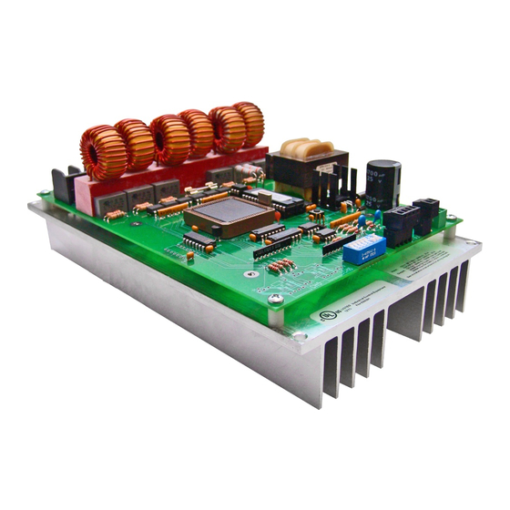
In order to have the controllers address different dimmers’ ranges, each pack/group of six channels have a specific range. The packs may be controlled by Cafe Duet code. FIG. 37 shows a sample AMX Lighting RE-DM4 controller and its internal components. -
Page 47: Control Curves And Low End Settings
AMX Lighting controller has provisions to set an individual low-end trim for each of the six dimming channels. The AMX Lighting dimming system employs a low-end cut- off that allows the dimmer to turn on to a specified level or to dim down to a specific level. The level at which the dimmer turns on is called the Low End Setting. - Page 48 AMX Lighting Programming RE-DM4 and RE-DM6 RADIA Eclipse Dimmer Modules...
-
Page 49: Appendix A: Amx Lighting Curves
AMX Lighting curve changes are implemented by a command to the AMX Lighting device. This example would set dimmer channel #1 to curve 6. The available curves that can be sent to the AMX Lighting controller are: 1, 2, 3, 4, 5, 6, 7, 8, 9, A, B, C, D, E, N, O, R, and F. - Page 50 The AMX test fixture for incandescent tests was set up using a constant Voltage feed of 120 VAC to the dimmer. The output of the dimmer was connected to (6) 100W GE lamps with a total load of 5 Amps.
- Page 51 This third characteristic is set at an output level of 1. The combinations of these characteristics allow AMX to tailor the outputs of different AMX Lighting dimmers.
-
Page 52: Curve Configuration
12% roll off 19% roll off for Lutron FDB 33% roll off for Lutron FDB S-curve #1 Log-curve #1 Log-curve #2 S-Curve #2 25% off Always ON 10% off Always off Reverse Linear RE-DM4 and RE-DM6 RADIA Eclipse Dimmer Modules... -
Page 53: Standard Dimming Curve (1)
FIG. 40 shows the curve 1 voltage output in 120 volts DC. FIG. 40 Curve 1 Voltage output in 120 Volts AC RE-DM4 and RE-DM6 RADIA Eclipse Dimmer Modules Curves Curve 1 – Standard dimming curve Curve 2 – Energy efficient, uses 10% less energy. - Page 54 FIG. 42 shows the low-voltage output of the RDM-HDC module. The voltage range is 4 to 12 VDC when attached to test ballast. FIG. 42 Curve 1 voltage output with Low End Setting @ 20 % Volts DC RE-DM4 and RE-DM6 RADIA Eclipse Dimmer Modules...
- Page 55 VAC or 35% reductions while a Low End Setting of 20 on Curve 1 is about a 50% reduction in dimming range. Small adjustments in a curve can cause significant changes in a dimmer's response. FIG. 43 Curve 1 with Low End Setting @ 5%, 10%, and 20% Volts RMS RE-DM4 and RE-DM6 RADIA Eclipse Dimmer Modules...
-
Page 56: Economical Dimming Curve (2)
FIG. 46 shows the low-voltage output of the RDM-HDC module. The voltage range is from 0 to 9 VDC when attached to test ballast. This curve can be used with 0-10 VDC dimming ballasts. FIG. 46 Curve 2 voltage output in volts DC RE-DM4 and RE-DM6 RADIA Eclipse Dimmer Modules... -
Page 57: 0-10Vdc Curve (3)
FIG. 50 shows the output voltage of the RDM-HDC module. The voltage range is from 2.6 to 9.3 VDC when attached to test ballast. This curve is primarily used with Advance Mark VII ballast using the RDM-HDC module. RE-DM4 and RE-DM6 RADIA Eclipse Dimmer Modules Appendix A: AMX Lighting Curves... - Page 58 Appendix A: AMX Lighting Curves FIG. 50 Curve 3 output in volts DC RE-DM4 and RE-DM6 RADIA Eclipse Dimmer Modules...
-
Page 59: 0-12Vdc Curve (4)
FIG. 54 shows the output voltage of the RDM-HDC module. Curve 4 is primarily used for control of Prescolite Intelect Ballast, using the RDM-HDC module. Its range is from 1 to 12 VDC. RE-DM4 and RE-DM6 RADIA Eclipse Dimmer Modules Appendix A: AMX Lighting Curves... -
Page 60: Lutron Fdb Curve (5)
18 volts. This curve can be useful with two wire dimmable fluorescent ballasts. Relay turn on level = 1% Dimming Range = 16 - 120 VAC. FIG. 55 Curve 5 Voltage output in Volts RMS FIG. 56 Curve 5 at 120V RE-DM4 and RE-DM6 RADIA Eclipse Dimmer Modules... - Page 61 FIG. 58 shows the output voltage of Curve 5 applied to the RDM-HDC module. It turns on to about 2 volts and rises to 12 VDC. There is a large increase in output above 98%. FIG. 58 Curve 5 Voltage output in volts DC RE-DM4 and RE-DM6 RADIA Eclipse Dimmer Modules Appendix A: AMX Lighting Curves...
-
Page 62: Advance Mark Vii Curve (6)
FIG. 62 is a plot shows the output voltage of Curve 6 applied to the RDM-HDC module. The turn on voltage is 2 VDC and rises to 12 VDC. Output increases rapidly above 95%. RE-DM4 and RE-DM6 RADIA Eclipse Dimmer Modules... - Page 63 Appendix A: AMX Lighting Curves FIG. 62 Curve 6 Voltage output in volts DC RE-DM4 and RE-DM6 RADIA Eclipse Dimmer Modules...
-
Page 64: 12% Roll Off (7)
After Level 50, the curve rolls off to 40 volts before cut off. This provides a 30% reduction in dimming. Relay turn on level = 1% Dimming Range = 39 - 1 20 VAC. FIG. 65 Curve 7 Voltage output in Volts RMS RE-DM4 and RE-DM6 RADIA Eclipse Dimmer Modules... - Page 65 FIG. 66 shows the DC output voltage of Curve 7 applied to the RDM-HDC module. It starts at 3 VDC and rises to 12 VDC. FIG. 66 Curve 7 Voltage output in volts DC RE-DM4 and RE-DM6 RADIA Eclipse Dimmer Modules...
-
Page 66: 19% Roll Off (8)
50% and then levels off to a 50 volts cut-off. This can be used on Advance Mark X ballasts. Relay turn on level = 1% Dimming Range = 52 - 120 VAC. FIG. 69 Curve 8 Voltage output in Volts RMS RE-DM4 and RE-DM6 RADIA Eclipse Dimmer Modules... - Page 67 FIG. 70 shows the output voltage of the RDM-HDC module. The low end starts at 4 volts and slowly rises to 12 VDC. This curve provides precise mid-range dimming. FIG. 70 Curve 8 Voltage output in volts DC RE-DM4 and RE-DM6 RADIA Eclipse Dimmer Modules...
-
Page 68: 33% Roll Off (9)
40%. This curve can be used to dim some fan motors. Use this curve when very little voltage range can be tolerated. Relay turn on level = 1% Dimming Range = 72 - 120 VAC. FIG. 73 Curve 9 Voltage output in Volts RMS RE-DM4 and RE-DM6 RADIA Eclipse Dimmer Modules... - Page 69 FIG. 74 shows the output voltage of the RDM-HDC module. Curve 9 starts at 5 volts and rises to 12 VDC. This provides a dimming range of 7 VDC. FIG. 74 Curve 9 Voltage output in volts DC RE-DM4 and RE-DM6 RADIA Eclipse Dimmer Modules...
-
Page 70: S-Curve #1 (A)
(Curve 1). It rolls off the high end quickly and extends the dimming range in the middle with a sharper roll off starting at 20% dimming level. Relay turn on level = 1% Dimming Range = 0 - 120 VAC. FIG. 77 Curve A Voltage output in Volts RMS RE-DM4 and RE-DM6 RADIA Eclipse Dimmer Modules... - Page 71 3 volts in the last 10% of its travel. This curve can be used with 0-12 VDC dimming ballasts like Prescolite Intelect ballasts. FIG. 78 Curve A Voltage output in volts DC RE-DM4 and RE-DM6 RADIA Eclipse Dimmer Modules...
-
Page 72: Log-Curve #1 (B)
FIG. 82 shows the output voltage of Curve B applied to the RDM-HDC module. The turn on voltage is 2VDC and rises to 10VDC. This curve can be used with 0-10 VDC dimming ballasts. RE-DM4 and RE-DM6 RADIA Eclipse Dimmer Modules... -
Page 73: Log-Curve #2 (C)
FIG. 82 Curve B Voltage output in Volts DC Log-Curve #2 (C) FIG. 83 Curve C at 120 VAC FIG. 84 Curve C at 240 VAC RE-DM4 and RE-DM6 RADIA Eclipse Dimmer Modules Appendix A: AMX Lighting Curves... -
Page 74: S-Curve #2 (D)
10VDC. This curve can be used with 0-10 VDC dimming ballasts. FIG. 86 Curve C Voltage output in Volts DC S-Curve #2 (D) FIG. 87 Curve D at 120 VAC RE-DM4 and RE-DM6 RADIA Eclipse Dimmer Modules... - Page 75 FIG. 90 shows the output voltage of the RDM-HDC module. Curve D is a variation of Curve A but at a 10% reduction. This curve can be used with 0-10 VDC dimming ballasts using the proper low-end cutoff. FIG. 90 Curve D Voltage output in volts DC RE-DM4 and RE-DM6 RADIA Eclipse Dimmer Modules Appendix A: AMX Lighting Curves...
-
Page 76: 10% Off Curve (N)
FIG. 93 shows the output voltage of the RDM-HDC module. This is an incandescent dimmer always on, starting at Level 9. Relay turn on level = 09. The RDM-HDC module will output 12 VDC above Level FIG. 93 Curve N Voltage output in Volts RMS RE-DM4 and RE-DM6 RADIA Eclipse Dimmer Modules... -
Page 77: Always Off Curve (O)
FIG. 96 is an incandescent dimmer, always off. No Level command will turn this dimmer on. Relay turn on level = none. The RDM-HDC module will output no voltage. FIG. 96 Curve O Voltage output in Volts RMS RE-DM4 and RE-DM6 RADIA Eclipse Dimmer Modules Appendix A: AMX Lighting Curves... -
Page 78: Always On Curve (F)
FIG. 100 is the voltage plot of the original Radia MC Series in FDB mode. This is provided for informational purposes only as the current RDD-DM4 does not support FDB mode due to large variety of FDB ballasts. AMX recommends using the RDM-FDB, RDM-FDB2, RDC-HFDB, or RDC-MDM module for 3-wire dimming control of FDB ballasts. - Page 79 FIG. 100 Curve M & S Voltage output in Volts RMS FIG. 101 Curve R at 120 VAC FIG. 102 Curve R at 240 VAC RE-DM4 and RE-DM6 RADIA Eclipse Dimmer Modules Appendix A: AMX Lighting Curves...
- Page 80 Curves 5 & B on the Radia Eclipse RE-DM6 at 120 VAC FIG. 105 Curves 6 & C at 120 VAC FIG. 106 Curves 6 & C on the Radia Eclipse RE-DM6 at 120 VAC RE-DM4 and RE-DM6 RADIA Eclipse Dimmer Modules...
- Page 81 FIG. 107 Curves A & D at 120 VAC FIG. 108 Curves A & D at 240 VAC RE-DM4 and RE-DM6 RADIA Eclipse Dimmer Modules Appendix A: AMX Lighting Curves...
-
Page 82: Appendix B: Radia Lighting Programming
Radia will not send feedback level updates. It will resume sending level updates back to the master upon reception of a command or channel that affects the dimmer/level. For more information on programming lighting systems, please refer to the AMX Lighting Programming section on page 37. -
Page 83: Channels
Ramp all dimmers up Ramp all dimmers down Ramp all dimmers to 100% RE-DM4 and RE-DM6 RADIA Eclipse Dimmer Modules Function Feedback only. Reflects the currently active presets. Ramps dimmer up at the default ramp time rate while channel is on. -
Page 84: Send_Strings
SEND_STRINGs The Radia supports a large number of strings, which can be used to allow interaction with a person using a terminal. These strings remain primarily to facilitate backward compatibility for other AMX lighting equipment. Conventions used in this protocol section of the document:... -
Page 85: Ramp Dimmers Up
SEND_STRING Radia,"13" Responses for the commands issued above respectively: "12,'01 STOP',13,10,'?'" "12,'GROUP STOP',13,10,'?'" "12,'ALL STOP',13,10,'?'" RE-DM4 and RE-DM6 RADIA Eclipse Dimmer Modules Appendix B: Radia Lighting Programming (if one dimmer specified) (if multiple dimmers specified) (if all ('A') dimmers specified) -
Page 86: Ramp Dimmers Down
Dimmer one stopped Dimmer group stopped All dimmers stopped (if one dimmer specified) (if multiple dimmers specified) (if all ('A') dimmers specified) Stop ramping dimmer 1 Stop ramping dimmers 2-4 Stop ramping all dimmers RE-DM4 and RE-DM6 RADIA Eclipse Dimmer Modules... -
Page 87: Ramp Active Preset Up
Response: PRESET <preset> RAMP STOP Example: SEND_STRING Radia,"'PS',13" Response: "12,'PRESET 001 RAMP STOP',13,10,'?'" (if preset 1 was ramping) RE-DM4 and RE-DM6 RADIA Eclipse Dimmer Modules Appendix B: Radia Lighting Programming Ramp preset up Stop ramping Ramp preset down Stop ramping... -
Page 88: Recall Preset
If <pack> is specified, it must be 1. Recall preset 2 at the saved rate Recall preset 56 over 10 seconds Record preset 3 at default rate Record preset 32 with 5 second ramp Request level status RE-DM4 and RE-DM6 RADIA Eclipse Dimmer Modules... -
Page 89: Set Curve
MINIMUM LEVEL IS: <percent> Example: SEND_STRING Radia,"'2LE20',13" Response: "12,'MINIMUM LEVEL IS: 020',13,10,'?'" RE-DM4 and RE-DM6 RADIA Eclipse Dimmer Modules Appendix B: Radia Lighting Programming Set dimmer 1 to curve 1 Set dimmers 1-4 to curve N Set all dimmers to curve 3... -
Page 90: Low End Status
Reboot String: [<pack>]QQQ Response: None Example: SEND_STRING Radia,"'QQQ',13" Response: none If <pack> is specified, it must be 1. Request current low end settings Request dimmer 3 status Reboot dimmer RE-DM4 and RE-DM6 RADIA Eclipse Dimmer Modules... -
Page 91: Set Default Level Time
SEND_STRING Radia,"'RT5',13" Response: "12,'RAMP TIME SET AT 005',13,10,'?'" A ramp time of zero (0) is invalid and will generate an error. RE-DM4 and RE-DM6 RADIA Eclipse Dimmer Modules Appendix B: Radia Lighting Programming Set default level ramp time to 3 seconds... -
Page 92: Ramp To Level
Ramp dimmer 6 to 50% over 5 seconds. Ramp all dimmers to 0% at the default ramp rate. Set dimmer 1 to undefined level Set dimmers 2-4 to undefined level Set all dimmers to undefined level RE-DM4 and RE-DM6 RADIA Eclipse Dimmer Modules... -
Page 93: Phase Query
Factory Default String: FACTORY Response: None Example: SEND_STRING Radia,"'FACTORY',13" Response: None RE-DM4 and RE-DM6 RADIA Eclipse Dimmer Modules Appendix B: Radia Lighting Programming check phase status Good response check phase status Fail on 2A and 2B Request version Restore Factory Defaults... -
Page 94: Send_Commands
6, inclusive. “A” indicates ALL dimmers. Value for preset number 1-128 Time value for fade (in sec- 0-255 onds) Ramp last preset up Stop ramping. Ramp preset 52 up Stop ramping preset 52 RE-DM4 and RE-DM6 RADIA Eclipse Dimmer Modules... -
Page 95: Ramp Preset Down (New)
Command: SP<preset>[T<time>] Response: None Examples: SEND_COMMAND Radia,'SP3' SEND_COMMAND Radia,'SP32T3' RE-DM4 and RE-DM6 RADIA Eclipse Dimmer Modules Appendix B: Radia Lighting Programming Ramp last preset down Stop ramping. Ramp preset 43 down Stop ramping preset 43 Stop ramping last preset Stop ramping preset 32... -
Page 96: Set Curve
Set dimmer 1 to curve 1 Set dimmers 1-4 to curve N Set all dimmers to curve 3 Request current curve settings Set minimum level of dimmer 2 to 20% Request current low end settings RE-DM4 and RE-DM6 RADIA Eclipse Dimmer Modules... -
Page 97: Reboot (New)
None Example: SEND_COMMAND Radia,'RT5' A ramp time of zero (0) is invalid. RE-DM4 and RE-DM6 RADIA Eclipse Dimmer Modules Appendix B: Radia Lighting Programming Reboot dimmer Set default level ramp time to 3 seconds. Set default level ramp time to 0 seconds (instantaneous). -
Page 98: Ramp To Level
Set dimmer 1 to undefined level. Set dimmers 2-4 to undefined level. Set all dimmers to undefined level. check phase status Good response check phase status Fail on 2A and 2B RE-DM4 and RE-DM6 RADIA Eclipse Dimmer Modules... -
Page 99: Appendix C: Troubleshooting
AMX Lighting controller were 96, you would type "PASS 96". The whole typed enter pass mode command is PASS 96<enter>, where <enter> means "Hit the enter key". 3. The AMX Lighting controller returns the string ERXON in acknowledgment. If you do not get the pack, you have not communicated or something else is wrong. -
Page 100: Testing Amx Lighting Features
AMX Lighting channel 5 = 50% AMX Lighting channel 6 = 50% Pack Status of Low End Trim Ramp all up in 20 sec. Ramp all down in 20 sec. Y-OK or Y-FAIL status is returned RE-DM4 and RE-DM6 RADIA Eclipse Dimmer Modules... -
Page 101: Hardware Issues
You can verify Radia Eclipse can turn the loads on/off by turning off all Axlink switches. This will set all circuits to 100%. RE-DM4 and RE-DM6 RADIA Eclipse Dimmer Modules Type this, then press Enter . Default is 6 & 7 on, all others off, which makes the Radia device 96 •... - Page 102 Appendix C: Troubleshooting RE-DM4 and RE-DM6 RADIA Eclipse Dimmer Modules...
- Page 103 Appendix C: Troubleshooting RE-DM4 and RE-DM6 RADIA Eclipse Dimmer Modules...
- Page 104 It’s Your World - Take Control™ 3000 RESEARCH DRIVE, RICHARDSON, TX 75082 USA • 800.222.0193 • 469.624.8000 • 469-624-7153 fax • 800.932.6993 technical support • www.amx.com...
Need help?
Do you have a question about the RADIA RE-DM4 and is the answer not in the manual?
Questions and answers