AMX NXC-ME260 Hardware Reference Manual
Master-ethernet card/module
Hide thumbs
Also See for NXC-ME260:
- Instruction manual (106 pages) ,
- Engineering drawing (1 page) ,
- Notice (1 page)

Related Manuals for AMX NXC-ME260


Summary of Contents for AMX NXC-ME260
- Page 1 Hardware Reference Guide NXC-ME260/64 NetLinx Master-Ethernet Card/Module ® N e t L i n x C e n t r a l C o n t r ol l e r s & C a r d s L a s t R e v i s e d : 5 / 3 0 / 2 0 0 8...
- Page 2 RMA number. AMX is not liable for any damages caused by its products or for the failure of its products to perform. This includes any lost profits, lost savings, incidental damages, or consequential damages. AMX is not liable for any claim made by a third party or by an AMX Dealer for a third party.
-
Page 3: Table Of Contents
NXC-ME260/64 Installation and Mounting Procedures ... 5 Mounting the ME260/64 into an NXS-NMS ... 5 Mounting the NXS-NMS Into an Equipment Rack ... 6 Mounting the NXC-ME260/64 in an NXF CardFrame or NXI ... 6 Replacing the Lithium Batteries ... 7 Connections and Wiring ...9 Setting the Configuration DIP Switch (for the Program Port) ... - Page 4 Table of Contents NXC-ME260/64 Hardware Reference Guide...
-
Page 5: Introduction
NetLinx Master Cards (NXC-M, NXC-ME, and NXC-MPE). The NXC-ME260/64 can be loaded in the Master card slot of an NXF NetLinx CardFrame, in an NXI Integrated Controller, or within an NXS-MHS Master/Hub Module. -
Page 6: Rear Panel Connectors
• 2-pin 3.5 mm mini-Phoenix (male) connector. • Use a 12 VDC-compliant power supply to provide power to the NXC-ME260/64 through the 2-pin 3.5 mm mini-Phoenix connector on the rear of the unit. • RJ11 connector connects to an AXB-SPE Server Port Expander. -
Page 7: Front And Rear Panel Components
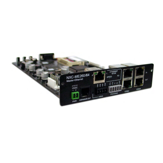
NXC-ME260/64 Specifications (Cont.) Other AMX Equipment: Front and rear panel components FIG. 1 shows the front and rear panel components of the NXC-ME260/64. Input LED (yellow) Output LED (red) Status LED (green) Front Rear Ethernet 10/100 connector NXC-ME260 Master-Ethernet 12VDC... -
Page 8: Rear Panel Leds: Icsnet/Icshub
L - Link LED (green) lights when the Ethernet cables are connected and ETHERNET terminated correctly 10/100 SPEED FD - Full Duplex LED (green) lights when running in full duplex mode, and is Off when running in half duplex mode NXC-ME260/64 Hardware Reference Guide... -
Page 9: Installation
4. Carefully remove the NXC-ME260/64 from its anti-static bag and place it aside. 5. Grasp the NXC-ME260/64 by the faceplate and direct the Program port (on the front of the card) into the opening on the rear of the NXS-NMS (FIG. 1). -
Page 10: Mounting The Nxs-Nms Into An Equipment Rack
FIG. 1 Component locations on both NXC-ME260/64 and NXS-NMS 7. Secure the NXC-ME260/64 faceplate to the NXS-NMS by using a Phillips-head screwdriver to turn the two faceplate securing screws in a clockwise direction. 8. Connect the 12 VDC power supply to the 2-pin PWR connector and apply power. -
Page 11: Replacing The Lithium Batteries
The NXC-ME260/64 is equipped with two lithium batteries (FG57-0013) that have a life of approximately 2.5 years to protect their memory. When DC power is on, the batteries (FIG. 4) are not used. - Page 12 NetLinx Module (NXS-xxx): Remove the rear panel from the Module, and remove the Master card. 3. Locate the two batteries behind the Program port on the NXC-ME260/64 circuit board. 4. Carefully slide one battery out of its socket and insert the new battery.
-
Page 13: Connections And Wiring
While the NI-900 is capable of receiving 8 and 9 bit characters, it cannot receive 7 bit, 1 stop bit data from a serial device (ex: 9600,N,7,1). It is recommended that the baud rate DIP switch be set prior to any installation of the NXC-ME260/64 card. -
Page 14: Baud Rate Settings
Power must be cycled to the unit after activating/deactivating this mode on the Program Port DIP switch #1. Position 5 Position 6 Position 7 Position 1 Position 8 NXC-ME260/64 Hardware Reference Guide... -
Page 15: Working With The Configuration Dip Switch
5-Pin Program port (rear panel) The table below lists the pinouts and signals for the grey rear panel 5-pin 3.5 mm mini-Phoenix Program port connector. Rear 5-Pin Program Port Pinouts and Signals Signal NXC-ME260/64 Hardware Reference Guide Signal Connections and Wiring... -
Page 16: Modes And Front Panel Led Blink Patterns
Both the NI-700 and NI-900 have an AXlink port and adjacent status LED (FIG. 2). This port allows the NI to support AMX Legacy AXlink devices such as G3 touch panels (ex: CP4/A) and PosiTrack Pilot devices. A green LED shows AXlink data activity. When the AXlink port is operating normally, blink... -
Page 17: Wiring Guidelines
3. Tighten the screws to secure the wire in the connector. Do not tighten the screws excessively doing so may strip the threads and damage the connector. NXC-ME260/64 Hardware Reference Guide NI-900 Connections and Wiring... -
Page 18: Wiring A Power Connection
Connect the 4-pin 3.5 mm mini-Phoenix (female) captive-wire connector to an external NetLinx device as shown in FIG. 4. To the Integrated Controller’s AXlink/PWR connector Top view FIG. 4 Mini-Phoenix connector wiring diagram (direct data and power) Power Supply To the external AXlink device Top view NXC-ME260/64 Hardware Reference Guide... -
Page 19: Using The 4-Pin Mini-Phoenix Connector For Data With External Power
Each port provides up to 500 mA of current. The following tables show the signal and pinouts/pairing information: ICSNet RJ-45 Signals Pin Signal-Master TX + TX - RX + RX - NXC-ME260/64 Hardware Reference Guide Local +12 VDC To the external AXlink device PWR (+) power supply (coming from GND (-) an external... -
Page 20: Icshub Port: Connections And Wiring
1 2 3 4 5 6 7 8 1 2 3 4 5 6 7 8 (male) port to the port on the second or downstream NetLinx Hub. Color orange-white orange ------ ------ ------ ------ brown-white brown NXC-ME260/64 Hardware Reference Guide... -
Page 21: Icshub Out Port
RX - no connection no connection FIG. 6 diagrams the RJ-45 pinouts and signals for the Ethernet RJ-45 connector and cable. FIG. 6 RJ-45 wiring diagram NXC-ME260/64 Hardware Reference Guide Color orange-white orange ------ ------ ------ ------... -
Page 22: Ethernet Leds
1319, or disable ICSP over Ethernet completely from either Telnet or the Program Port located on the rear of the Master itself. This type of communication is used by the various AMX product for communication amongst themselves. SPD - Speed LED... -
Page 23: Spe Port Connection/Wiring
7 bit, 1 stop bit data from a serial device (ex: 9600, N,7,1). SPE Port Connection/Wiring Use an RJ-11 cable to connect the NXC-ME260/64 to an AXB-SPE Slave Port Expander. EXPANSION OUT port on the rear panel of the AXB-SPE (FIG. 8). -
Page 24: Spe Cable Pinout Information
Connections and Wiring SPE cable pinout information The following table gives pinout information for the RJ-11 SPE connector. AMX supplies a 6" RJ-11 cable with the AXB-SPE. The is Ground; the others are all pin-to-pin connections. SPE Connector Pinouts and Signals Do not use a standard phone extension cable;... - Page 25 Connections and Wiring NXC-ME260/64 Hardware Reference Guide...
- Page 26 It’s Your World - Take Control™ 3000 RESEARCH DRIVE, RICHARDSON, TX 75082 USA • 800.222.0193 • 469.624.8000 • 469-624-7153 fax • 800.932.6993 technical support • www.amx.com...
Need help?
Do you have a question about the NXC-ME260 and is the answer not in the manual?
Questions and answers