AMX NXC-ME260/64 Instruction Manual
Hide thumbs
Also See for NXC-ME260/64:
- Quick start manual (2 pages) ,
- Programming manual (162 pages) ,
- Hardware reference manual (26 pages)
Table of Contents
Advertisement
Quick Links
Download this manual
See also:
Programming Manual
Advertisement
Table of Contents

Subscribe to Our Youtube Channel
Related Manuals for AMX NXC-ME260/64


Summary of Contents for AMX NXC-ME260/64
- Page 1 IN STR U CT IO N MAN U AL N XC - M E 2 6 0 / 6 4 NE TLIN X MASTER ETHERN ET CAR D...
-
Page 2: Important Safety Instructions
COPYRIGHT NOTICE AMX© 2016, all rights reserved. No part of this publication may be reproduced, stored in a retrieval system, or transmitted, in any form or by any means, electronic, mechanical, photocopying, recording, or otherwise, without the prior written permission of AMX. Copyright protection claimed... -
Page 3: Table Of Contents
Mounting the NXC-ME260/64 into an NXS-NMS Module ..........6 Mounting the NXS-NMS Into an Equipment Rack................... 6 Mounting the NXC-ME260/64 in an NXF CardFrame or NXI..........7 Connections and Wiring ..................8 Setting the Configuration DIP Switch (for the Program Port) .......... 8 Baud Rate Settings .......................... -
Page 4: Nxc-Me260/64
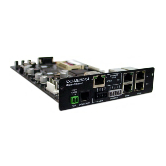
PROGRAM Port (5-pin) ICSNet (OUT) Port ICSHub (OUT) Port NXC-ME260/64 FIG. 1 NOTE: When working with the NXC-ME260/64, verify you are using the latest version of NetLinx Studio (available for download from www.amx.com). Specif ications NXC-ME260/64 Specif ications Dimensions (HWD): •... - Page 5 NXC-ME260/64 NXC-ME260/64 Specif ications (Cont.) Front Panel Components (Cont.) LEDs • Status: Green LED blinks to indicate that the system is programmed and communicating properly. • Output: Red LED blinks when the Master transmits data, sets channels On and Off, sends data strings, etc.
-
Page 6: Installation
Carefully remove the NXC-ME260/64 from its anti-static bag and place it aside. Grasp the NXC-ME260/64 by the faceplate and direct the Program port (on the front of the card) into the opening on the rear of the NXS-NMS (FIG. 2). -
Page 7: Mounting The Nxc-Me260/64 In An Nxf Cardframe Or Nxi
Mounting the NXC-ME260/64 in an NXF CardFrame or NXI The NXC-ME260/64 can be installed in a NetLinx CardFrame (NXF) or NetLinx Integrated Controller (NXI). In both cases, the card mounts in a horizontal position, through the Master card slot on the rear panel of the enclosure. To install a Master card into either an NXF CardFrame or NXI Integrated Controller (FIG. -
Page 8: Connections And Wiring
The Configuration DIP switch is located on the front of the Integrated Controllers. NOTE: While the NXC-ME260/64 is capable of receiving 8 and 9 bit characters, it cannot receive 7 bit, 1 stop bit data from a serial device (ex: 9600,N,7,1). -
Page 9: Working With The Configuration Dip Switch
Program Port Connections and Wiring There are Program ports located on the front and rear of the NXC-ME260/64 for easy access. Because these ports share the same circuitry, you should never use both at the same time; doing so will result in communication and/or programming errors. -
Page 10: Modes And Front Panel Led Blink Patterns
AxLink Port and LED The AxLink port and adjacent status LED on the front panel allows the NXC-ME260/64 to support AMX Legacy AxLink devices such as G3 touch panels (ex: CP4/A) and PosiTrack Pilot devices. A green LED shows AxLink data activity. When the AxLink port is operating normally, blink patterns include: Off - No power, or the controller is not functioning properly ... -
Page 11: Wiring A Power Connection
Controller’s Phoenix connector when using an external power supply. Make sure to connect only the GND wire on the AxLink/PWR connector when using a separate 12 VDC power supply. Do not connect the PWR wire to the AxLink connector’s PWR (+) opening. NXC-ME260/64 - Instruction Manual... -
Page 12: Icsnet Port: Connections And Wiring
Do not connect the last hub in a daisy-chain configuration into the first Hub. ICSHub IN Port Pinouts and Signals ICSHub IN Pinouts and Signals Signal Color TX - orange-white TX + orange ------ ------ ------ ------ ------ ------ ------ ------ RX - brown-white RX + brown NXC-ME260/64 - Instruction Manual... -
Page 13: Icshub Out Port
Sample command: SET ETHERNET MODE AUTO The ME260/64 only allows you to set the LAN mode to AUTO negotiate the LAN connection speed. Using any of the other connection modes (10 Half/Full or 100 Half/Full) will result in an error. NXC-ME260/64 - Instruction Manual... -
Page 14: Lan Ports Used By The Integrated Controller
Master can be configured to utilize a different port than 10500 or to disable integration! Solutions completely. NOTE: While the NXC-ME260/64 is capable of receiving 8 and 9 bit characters, it cannot receive 7 bit, 1 stop bit data from a serial device (ex: 9600, N,7,1). -
Page 15: Spe Cable Pinout Information
FIG. 11 SPE Cable Pinout Information AMX supplies a 6" RJ-11 cable with the AXB-SPE. Do not use a standard phone extension cable; it will not work with the AXB-SPE. The following table gives pinout information for the RJ-11 SPE connector:... -
Page 16: Replacing The Lithium Batteries
(other than the allowed number of cells in series or parallel) power source that would increase the forward current through the cells. The NXC-ME260/64 is equipped with two lithium batteries (FG57-0013) that have a life of approximately 2.5 years to protect their memory. - Page 17 © 2016 Harman. All rights reserved. Metreau, NetLinx, AMX, AV FOR AN IT WORLD, HARMAN, and their respective logos are registered trademarks of Last Revised: HARMAN. Oracle, Java and any other company or brand name referenced may be trademarks/registered trademarks of their respective companies.
Need help?
Do you have a question about the NXC-ME260/64 and is the answer not in the manual?
Questions and answers