Ecolab Elados EMP KKS E60 Operating Instructions Manual
Hide thumbs
Also See for Elados EMP KKS E60:
- Short operating instructions (54 pages) ,
- Operating instructions manual (406 pages)

Related Manuals for Ecolab Elados EMP KKS E60


Summary of Contents for Ecolab Elados EMP KKS E60
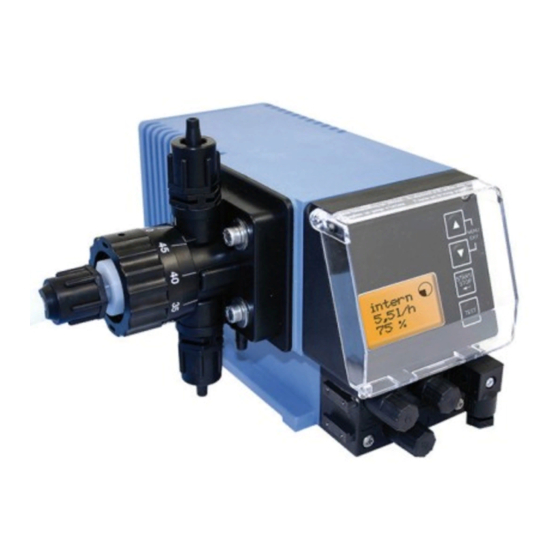
- Page 1 Operating Instructions ® Elados EMP KKS E60 ® PLUS Elados EMP KKS E60 Softwareversion 4.0 or 4.1 Fig. 0.1 EMP KKS E60 Fig. 0.2 PLUS EMP KKS E60 (with Dongle-Box) 417101774_EMP_KKS_E60_E.doc Rev. 8-03.10...
-
Page 2: Table Of Contents
Table of contens General ........................5 Warranty coverage ............................5 Contact address / Manufacturer........................5 Safety .........................6 Safety Notes ..............................6 Emphases.................................6 Numberings ..............................6 Special safety Notes for maintenance and repair work..................6 Delivery scope......................7 PLUS Upgrade accessories for the EMP KKS E60 ....................7 Functional description ....................8 Mechanical functions ............................8 Electronic functions............................8 PLUS... - Page 3 Menu description .....................31 10.1 Main menu..............................31 10.1.1 Overview.................................31 10.2 Operation mode ..............................32 10.2.1 Selecting.................................32 10.2.2 Operation mode / internal ..........................32 10.2.2.1 Selecting.................................32 10.2.2.2 Display in the operating display/ Setting ......................33 10.2.3 Operation mode / pulse ..........................33 10.2.3.1 Selecting.................................34 10.2.3.2 Display in the operating display/ Setting ......................34 10.2.4 Operation mode / current (external standard signal)..................35 10.2.4.1...
- Page 4 10.4.2 Calibration pump.............................54 10.4.2.1 Preparation ..............................54 10.4.2.2 Calibration / Start ............................55 PLUS 10.4.3 Calibration pump with oval gear meter (OGM ) ..................55 10.4.3.1 Preparation ..............................55 10.4.3.2 Calibration / Start ............................56 10.4.4 Calibration / Manual............................57 10.4.4.1 Calibration data table............................57 10.5 Operating data ..............................57 10.5.1 Overview.................................58 10.5.2...
-
Page 5: General
• Only original spare parts must be used for repairs. • The warranty claim is invalidated if the pump housing is opened. In addition, the general warranty and service conditions of the company ECOLAB Engineering GmbH are applicable. Contact address / Manufacturer ECOLAB Engineering GmbH Raiffeisenstraße 7... -
Page 6: Safety
Safety Safety Notes • Connection and repair work on the membrane metering pump must only be performed by authorized technical personnel. • The power supply plug must always be disconnected before starting any work on electrical components. • Appropriate protective clothing must be worn for any maintenance and repair work. •... -
Page 7: Delivery Scope
Delivery scope The delivery scope consists of: • Fig. 3.1 metering pump, version EMP KKS E60 including mains power supply cable (2 m) with shock-proof plug and dummy plug for inputs and outputs Fig. 3.2 • 5-terminal connector plug for pulsed or standard signal input •... -
Page 8: Functional Description
Functional description Mechanical functions ® ELADOS EMP KKS series of metering pumps take the form of electrically (motor) driven diaphragm displacement pumps. The membranes are for the pre-delivery, the piston is for the metering. Because of the permanent overpuls refeeding this metering pump works self venting. The metering pumps are suitable for use with clean, non-abrasive metering media with a viscosity of up to 200 mPas (measuring manner: Brookfield). -
Page 9: Setup
Setup EMP KKS E60 Fig. 5.1 Fig. 5.2 PLUS EMP KKS E60 Fig. 5.3 Fig. 5.4 Pos. Description Suction valve (connection on the suction side) Diaphragm breakage sequence Venting connection (refeeding into the container) Stroke length adjustment Pump head Pressure valve (connection on the pressure side) Rail for connecting the dongle box Dongle box Flow direction of the metering medium... -
Page 10: Indicators / Controls / Jacks
Indicators / Controls / Jacks PLUS 5.3.1 EMP KKS E60 and EMP KKS E60 versions Fig. 5.5 Pos. Description Control knob for setting the stroke length Menu/Exit, up arrow key Menu/Exit, down arrow key Start/Stop key (Enter function) Test key Graphical display Pos. -
Page 11: Mounting
Mounting The installation must only be performed by authorized personnel and the general guidelines WARNING and local installation regulations must be observed! - The metering pump should be fitted in an easy-to-access, frost-free location. The ambient temperature must not exceed +40° C. - The mounting position of the device must be horizontal. -
Page 12: Device Installation
Device installation Hydraulic installation 7.1.1 Installation examples The installation examples and applications provided here are of a functional nature. They NOTE give an overview of installation types which are correct or to be avoided for the correct functioning of the pump. Specific measures and protection devices for the metering of dangerous or aggressive chemicals are not provided here. - Page 13 Fig. 7.3 The suction pipes must be kept as short as possible. Long and twisted suction pipes may lead to air buildup in the system. The max. suction height is 2 m and the max. flow velocity is 0.3 m/s! (see also chapter 14.3 “Technical Specifications“)
-
Page 14: Connecting The Suction Line And Return Line
7.1.2 Connecting the suction line and return line Fig 7.6 Pos. Description Union nut Clamping piece Connection piece O-ring Fixing hole When connecting the suction and pressure pipes, ensure that the O-rings CAUTION (Pos. 19) are fixed to the connectors so as to achieve the required seal. -
Page 15: Connection Of Pressure Line
7.1.3 Connection of pressure line Fig. 7.7 Cut off the metering hose or pipe straightly. Push over the union nut (pos. 2) and crimping ring (pos. 3). Attach the hose or the pipe onto the connection piece (pos. 4) until the stop motion and screw it up by hand. -
Page 16: Connector Assignments Of Slot I (3-Terminal) Input For Low-Level Advance Warning And Empty Report
7.2.2 Connector assignments of Slot I (3-terminal) input for low-level advance warning and empty report Fig. 7.9 1: Low-level advance warning 3: Empty report input 4: GND ( ┴ ) (plug assignments: see also chapter 14.5.1 “Technical Specifications“) 7.2.2.1 Installing the suction pipe with low-level advance warning and empty report When using a suction pipe, remove the dummy connector and mount the suction pipe connector. -
Page 17: Connector Assignment Of Slot Ii (5-Terminal) Input For Pulse Signal, Standard Signal, Metering Lock, Batch And Metering Monitoring
7.2.3 Connector assignment of slot II (5-terminal) input for pulse signal, standard signal, metering lock, batch and metering monitoring Fig. 7.11 1: output 5 V (loadable with max. 50 mA) 2: pulse input (also as configurable batch / metering monitoring; see 10.3.13 &... -
Page 18: Installing The Standard Signal Control
7.2.3.2 Installing the standard signal control Fig. 7.13 7.2.3.3 Installing the control via the metering lock The metering lock funktion must be activated in menue first. (see chapter: 10.3.7 Configuring the metering lock). NOTE The metering lock is available in all operation modes. Fig. -
Page 19: Installing The Batch Function
7.2.3.4 Installing the batch function The batch funktion must be activated in menue first. (see chapter 10.3.15 batch configuration) HINWEIS According to the requirements, the input of the batch pulse (contact 2+4 or contact 3+4) must be configured. (see chapter 10.3.15.) Fig. -
Page 20: Connector Assignments Of Slot Iii (4-Terminal) Output For Alarm And Stroke Signal
7.2.4 Connector assignments of slot III (4-terminal) output for alarm and stroke signal Fig. 7.17 1: Low-level advance warning, empty report and fault 2: Low-level advance warning, empty report and fault 3: Stroke signal (+) 4: Stroke signal (-) (plug assignments: see also chapter 14.5.3 “Technical Specifications“) Remove the protective cap... -
Page 21: Installing The Stroke Signal Output At 24 V / Dc
7.2.4.2 Installing the stroke signal output at 24 V / DC Fig. 7.19 7.2.4.3 Installing the alarm output at 115/230 V / AC Fig. 7.20 Standard configuration: closed = empty report container active or error message Other configuration see chapter 7.2.4.4 (Hardware) and chapter 10.3.9... -
Page 22: Hardware Migration For Alarm Contact
Pin 1 & 2 up to Pin 2 & 3. preset. WARNING: NOTE Changes to the circuit board may only be performed by service personnel of the company ECOLAB-Engineering or trained technical personnel! 7.2.4.4.1 In the alarm output "ON" configuration setting (See Menu Description in chapter 10.3.9) If “No Alarm“... -
Page 23: Upgrading The Emp Kks E60 To The Emp Kks E60
PLUS Upgrading the EMP KKS E60 to the EMP KKS E60 PLUS To upgrade the EMP KKS E60 to the EMP KKS E60 and thus access the additional functions, obtain the dongle box from our range of accessories. (Part No. 248606). Fitting the dongle box Fig. -
Page 24: Connector Assignments Of The Slots
Connector assignments of the slots 8.2.1 Connector assignments of slot V (5-terminal), input for oval gear meter Fig. 8.4 1: Supply for oval gear meter 5 V 2: Pulse input for oval gear meter, type OGM/OGC (standard) PLUS 3: Pulse input for oval ge ar meter, type OGM 4: GND 5: Free for future use Remove the protective cap... -
Page 25: Connector Assignments Of Slot Vii (5-Terminal) Input For Batch Pulse And Metering Lock
8.2.2 Connector assignments of Slot VII (5-terminal) input for batch pulse and metering lock Fig. 8.6 1: 5 V supply 2: Input for batch pulse 3: Input for metering lock 4: GND 5: Free for future use Remove the protective cap Mount the connector plug according to the connector assignment. -
Page 26: Installing The Metering Lock (Optional Connector Vii Or Viii)
8.2.2.2 Installing the metering lock (optional connector VII or VIII) The metering lock function must be activated in menue first. (see chapter: 10.3.7 configuration meterin lock) HINWEIS The metering lock is available in all operation modes. Fig. 8.8 417101774_EMP_KKS_E60_E.doc - 26 - Rev. -
Page 27: Connector Assignments Of Slot Viii (5-Terminal) Input For Pulse, Standard Signal Input And Metering Lock
8.2.3 Connector assignments of Slot VIII (5-terminal) input for pulse, standard signal input and metering lock Fig. 8.9 1: 5 V supply 2: Input for external pulses 3: Input for metering lock 4: GND 5: Input for standard signal Remove the protective cap Mount the connector plug according to the connector assignment. -
Page 28: Installing The Standard Signal (Ma)
8.2.3.2 Installing the standard signal (mA) Fig. 8.11 8.2.3.3 Installing the metering lock The metering lock function must be activated in menue first. (see chapter: 10.3.7 configuration meterin lock) HINWEIS The metering lock is available in all operation modes. Fig. 8.12 417101774_EMP_KKS_E60_E.doc - 28 - Rev. -
Page 29: Startup
Startup Switching on the pump Fig. 9.1 2 sec Press START/STOP key (min. 2 sec.). Switching off the pump Fig. 9.2 5 sec Press START/STOP key (min. 5 sec.). Key functions Description Fig. 9.3 MENU/EXIT function entry and exiting of the menu levels (keep keys pressed down together) Modify set values upwards Modify set values downwards... -
Page 30: Software Version Display
9.4.1 Software version display Fig. 9.6 The current software version is displayed in the top right of the main menu screen (Fig. 9.6). Lowercase letters after the software number (Fig. 9.6) describe internal software modifications that do not affect the operation of the device. -
Page 31: Menu Description
Menu description 10.1 Main menu The main menu can be accessed while the pump is operating. It is started by simultaneously pressing the keys. Simultaneously press the keys again to return to the operating display. 10.1.1 Overview Fig. 10.1 Operation mode see chapter 10.2 Configuration... -
Page 32: Operation Mode
10.2 Operation mode 10.2.1 Selecting Fig. 10.2 Adjustments: • internal chapter 10.2.2 • pulse chapter 10.2.3 • current chapter 10.2.4 10.2.2 Operation mode / internal The “internal” operation mode can be used to operate the metering pump without external signals. The following display options can be selected: •... -
Page 33: Display In The Operating Display/ Setting
10.2.2.2 Display in the operating display/ Setting The metering rate can be configured/adjusted in the operating display during operations. If the newly set value is not confirmed within 10 seconds by pressing the START/STOP NOTE key, the system reverts to the primarily value. Strokes/min Fig. -
Page 34: Selecting
10.2.3.1 Selecting Fig. 10.8 10.2.3.2 Display in the operating display/ Setting The multiplication and division factors are configured/adjusted in the operating display. This can take place while the pump is operating. Multiplication Fig. 10.9 If the newly set value is not confirmed within 10 seconds by pressing the NOTE... -
Page 35: Operation Mode / Current (External Standard Signal)
10.2.4 Operation mode / current (external standard signal) In the “current” operation mode, the pump functions on the basis of an incoming standard signal.The incoming signal (0/4-20 mA; 20-0/4 mA or adjustable) is converted into a metering frequency 0-100 % (stroke/pause ratio), e.g.: The following operating options can be selected: •... -
Page 36: Display In The Operating Display
10.2.4.1.1 Setting operation mode / current / user defined NOTE The difference in the set values must be greater than or equal to 5. (e.g. min 10 max 15). Fig. 10.12 10.2.4.2 Display in the operating display Display Description Fig. 10.13 Range of input signal, preset in the menu Actual connected current value Stroke frequency in %... -
Page 37: Configuration
10.3 Configuration 10.3.1 Overview Fig. 10.14 Configuration of: chapter: Menu language 10.3.3 Units 10.3.4 Code entry 10.3.5 Startup settings 10.3.6 Metering lock 10.3.7 Low-level contact 10.3.8 Alarm output 10.3.9 Pulse memory 10.3.10 Oval gear meter 10.3.11 Metering controller 10.3.12 Metering monitoring 10.3.13 MicroFlow 10.3.14... -
Page 38: Configuration / Unit
10.3.4 Configuration / Unit If ‘litre’ is selected for the ‘internal’ operation mode (see chapter 10.2.2), this can be used to change the display from litres/h to gallons/day (1 gallon = 3,785 litres). 10.3.4.1 Selecting Fig. 10.17 Default setting = liter 10.3.5 Configuration / Code With this setting, a four-digit number combination can be assigned to secure the setting... -
Page 39: Setting
10.3.5.2 Setting Fig. 10.19 10.3.6 Configuration / Autostart This function determines whether the pump is set to ‘OFF’ (‘Standby‘ in V 4.0) when the mains connection is re-established following a power cut or if the pump should immediately recommence functioning in the configured operation mode. 10.3.6.1 Selecting Fig. -
Page 40: Selecting
10.3.7.1 Selecting Fig. 10.21 interrogation of the metering lock is inactive. (Default setting) interrogation of the metering lock is active. 10.3.8 Configuration / Low-level contact This function specifies whether an open or a closed contact at the level input (plug I, see chapter 7.2.2.1) is regarded as level OK. -
Page 41: Selecting
10.3.9.1 Selecting Fig. 10.23 = When an alarm is triggered, the relay is pulled in for the alarm output. (Default setting) = When an alarm is triggered, the relay is not pulled in for the alarm output. In addition to the function mode of the relay, it is also possible to select whether the alarm output relay contact is closed (closing function on, default... -
Page 42: 10.3.10.2 Display In The Operating Display With An Active Pulse Memory
10.3.10.2 Display in the operating display with an active pulse memory Display in operation Meaning Description Fig. 10.25 Pulse memory active Number of pulses received Pulse multiplication Set factor (Example: 10 external pulses become 20 strokes) Fig. 10.26 Pulse division (Example: 10 external pulses become 20 strokes) -
Page 43: Configuration / Metering Controller
PLUS PLUS 10.3.12 Configuration / Metering controller“ (only E60 & OGM If the metering controller is active, in conjunction with the connection of an PLUS recording the metering rate, the pump’s metering performance in ‘internal’ and ‘current’ modes can be adjusted within the performance limits. I.e. if it is not possible to reach the set delivery rate due to external influences, then the metering frequency of the pump is automatically increased until the desired discharge flow is reached. -
Page 44: 10.3.12.2 Display In The Operating Display With An Active Metering Controller
10.3.12.2 Display in the operating display with an active metering controller Fig. 10.29 ▼ = Downward metering divergence The pump is currently delivering less than the preset stroke frequency (here 100/min for example) requires. Metering frequency is increased automatically until the actual value matches the target value. -
Page 45: 10.3.13.2 Metering Monitoring / Stop Pump
10.3.13.2 Metering monitoring / Stop pump The “stop pump” function is used to set whether or not the pump should be stopped if a “metering monitoring alarm” is triggered. Fig. 10.34 - Pump is not stopped when a “metering monitoring alarm” is triggered. -
Page 46: Metering Monitoring / Deviation
PLUS PLUS 10.3.13.4 Metering monitoring / Deviation (only at E60 & OGM or OGM A tolerance in % is set under “deviation”. The actual incoming pulse rate recorded by the oval gear meter within the pump interval to be monitored (see chapter 10.3.13.3 configuration/strokes) is compared with the target pulse rate defined during calibration. -
Page 47: Oval Gear Meter Pulse Display (Only E60 Plus )
PLUS 10.3.13.6 Oval gear meter pulse display (only E60 This display shows the number of pulses recorded during the last calibration process (running time during calibration = 1 min). If the value shown is less than 60, metering monitoring using an oval gear meter is only possible to a limited extent. -
Page 48: Microflow Plus / Stop Pump
PLUS 10.3.14.2 MicroFlow / Stop pump The “stop pump” function is used to set whether or not the pump stops if a “metering monitoring alarm” is triggered. Fig. 10.40 Pump is not stopped in the event of an „Alarm metering monitor function“... -
Page 49: Microflow Plus / Metering Break
PLUS 10.3.14.5 MicroFlow / Metering break When handling media with a tendency to emit gas, gas bubbles form in the system after extended downtimes, resulting in corrupted volume values of the quantity to be metered and PLUS subsequently to the non-detection of the metering strokes by the MicroFlow and the issuance of an alarm. -
Page 50: Microflow Plus / Calibration
PLUS 10.3.14.7 MicroFlow / Calibration Use the "Calibration" option to newly calibrate the transducer during initial installation or when changing the product. The pump must be running and the metering medium must flow through the transducers without any bubbles before starting the calibration process. On activating the “calibration”... -
Page 51: Batch / Input (Only At E60 Without Dongle Box)
Fig. 10.47 10.3.15.3 Batch / Input (only at E60 WITHOUT Dongle box) The “Input” setting is used to determine which input (pulse input or metering lock) at plug II of the pump should be used to evaluate the start pulse for the batch metering. The start pulse cable connection depends on the selected input: Input pulse = plug II Pin 2+4... -
Page 52: 10.3.15.4 Display In The Operating Display
Fig. 10.48 Default setting = Metering lock 10.3.15.4 Display in the operating display Fig. 10.49 Description Operation mode Quantity remaining to be metered Strokes remaining to be executed PLUS 10.3.16 Configuration Degas PLUS” On activating the “Degas function and connecting an appropriate degassing valve, this function enables the metering system to be degassed for a controlled time period. -
Page 53: 10.3.16.2 Degas / Degas Strokes
10.3.16.2 Degas / Degas strokes The number of strokes that should be processed during a degassing interval is recoded under “degas strokes”. Setting range: 1-100 Fig. 10.51 Default setting = 0 10.3.16.3 Degas / Degas break The time between two degassing intervals is set under “degas break”. PLUS If a metering request is submitted during this period, this is processed and the Degas break time is reset and restarted. -
Page 54: Calibration
10.4 Calibration 10.4.1 Overview The procedure and display during the calibration process differ depending on whether or not an oval gear meter is connected. Fig. 10.53 Calibration pump: • see chapter 10.4.2 Calibration pump with oval gear meter: • see chapter 10.4.3 10.4.2 Calibration pump... -
Page 55: Calibration / Start
10.4.2.2 Calibration / Start Fig. 10.55 The pump runs 122 strokes (ca. 1 min). The strokes are counted down from 122 to 0. NOTE By activating the 'Menu/Exit’ function, the running calibration can be interrupted. After the running process, the amount removed from the measuring cylinder (see chapter 10.4.2.1 “Preparation”) must be read off. -
Page 56: Calibration / Start
10.4.3.2 Calibration / Start Fig. 10.57 The pump runs 122 strokes (ca. 1 min). The strokes are counted down from 122 to 0. The oval gear meter pulses (OGM pulses) are counted upwards from 0. By activating the 'Menu/Exit’ function, the running calibration can be interrupted. NOTE If the OGM pulses are not displayed, check all the connections to the pump! After the running process, the amount removed from the measuring cylinder (see... -
Page 57: Calibration / Manual
10.4.4 Calibration / Manual If the calibration value to be entered is known, a “dry calibration” (immediate entry of the value without a previous calibration process) can be conducted. However, this method is not very accurate as no consideration is given to the on-site conditions (back-pressure, viscosity, cable cross-chapters and lengths etc). -
Page 58: Overview
10.5.1 Overview Fig. 10.60 see chapter 10.5.2 see chapter 10.5.3 see chapter 10.5.4 10.5.2 Operating data / Operating hours The pump running time (number of strokes • 480 ms) since it was first commissioned or last reset is displayed. 10.5.2.1 Selecting / Displaying / Deleting Fig. -
Page 59: Selecting / Displaying / Deleting
10.5.3.1 Selecting / Displaying / Deleting Abb. 10.62 10.5.4 Operating data / Amount of pulses The number of pulses received via the pump’s pulse input (plus II pins 3+4, see chapter 7.2.3 “Plug II connection details”) since it was first commissioned or last reset is displayed. 10.5.4.1 Selecting / Displaying / Deleting Fig. -
Page 60: Maintenance
Maintenance Metering pumps must only be maintained by technically competent and authorized CAUTION persons. The maintenance interval is quarterly. Shorter intervals are recommended in the event of NOTE heavy loads (e.g. continuous use). The following inspections are recommended: suction pipes and pressure pipes for leak-free connections suction valve and pressure valve (chapter 11.1, Fig. -
Page 61: Inserting The Metering Valves In The Correct Positions
11.1.1 Inserting the metering valves in the correct positions Fig. 11.2 On the suction valves and flow valves, the flow direction is marked with an engraved arrow. When inserting it, always ensure that the valves are inserted according to the flow direction! 11.2 Replacing the diaphragm and pump head Fig. -
Page 62: Replacement Of Ceramics Cylinder Unit With Piston
11.3 Replacement of ceramics cylinder unit with piston Procedure as described in chapter 11.2. Fig. 11.4 Pos. Designation Ceramics cylinder unit O-Ring, Ø 22 x 2 (FPM) O-Ring, Ø 22 x 2 (EPDM) Spring O-Ring, Ø 14 x 2,5 Valve nipple Washer Valve ball O-Ring, Ø... -
Page 63: Description Of The Stroke Scale
11.4 Description of the stroke scale Pos. Description Fig. 11.5 Stroke adjustment knob Grub screws (2 x opposed) Adjustment knob markings pict. 32 = 0 point) Receiver for the adjustment knob (teethed) Nonius scale Metering connector Fig. 11.6 From factory-side the metering pump is set to nominal pressure, in accordance with the metering curves. -
Page 64: Operating Faults
Operating faults 12.1 Metering warning messages (display) If external signals are no longer being processed and the output signals (empty, fault) are switched off, the following error messages can be shown on the display of the metering pump: Display Meaning Effect Cause Remedy... -
Page 65: Trouble Shooting
12.2.1 Trouble shooting Fault Possible cause Remedy metering pump does not mains power cable damaged change mains power cable work, no display indicator incorrect voltage check mains voltage pump has no suction deposits, adhesions or drying- rinse the metering head through despite venting and max. -
Page 66: Wearing Parts And Spare Parts (Standard Version)
Wearing parts and spare parts (standard version) Fig. 13.1 Pos. Designation article-no. Square nut 413226005 Headless screw 413401178 Stroke adjustment button 34070193 Washer 34070186 Adjustment nut 34070185 Suction-/Return valve, SDVPVFPKE000 G3/8-G3/8-99 248405 Connection set 3/8“ PVDF for hose 6/8, 6/10, 6/12 mm 247629 Pump head, PVDF 34070192... -
Page 67: Technical Specifications
Technical Specifications 14.1 Pump key 1. Electrical version (for explanation, see chapter 14.1.1) E 60 = 2. Pump output 50 Hz (60 Hz) 00002 0,2 l/h (0,24 l/h) 00005 0,5 l/h (0,6 l/h) 00009 0,9 l/h (1,1 l/h) 00014 1,4 l/h (1,7 l/h) 3. - Page 68 Pump key 2 11.Connection pre-delivery = set for PE hose 6/8 = set for PVC hose 6/10 = set for PVC-fabric 6/12 = set for hose 6/8, 6/10, 6/12 (standard) 12. Connection pressure side = set bent for PE/PTFE hose 2/4 (standard for 0,2 l/h) = set bent for PE/PTFE hose 4/6 (standard for 0,5 - 1,4 l/h)
-
Page 69: Pump Key Definition E60
14.1.1 Pump key definition 1. Electrical version • On/Off switch for switching the pump • mechanical stroke adjustment • backlit graphical display, 4 control keys • individual stroke control (each stroke is executed completely) • metering control via stroke signal output (computed) or via external metering monitoring system •... -
Page 70: Dimensions
14.2 Dimensions Fig. 14.1 417101774_EMP_KKS_E60_E.doc - 70 - Rev. 8-03.10... -
Page 71: Technical Specifications "Overview Tables
14.3 Technical specifications "Overview tables" 14.3.1 General data Pump type Description 00002 00005 00009 00014 Supply voltage 230 V / 50/60 Hz ± 10 % (special voltages on request) max. power consumption I 115V 50/60 Hz 0,2 A / 0,21 A 230V 50/60 Hz 0,09 A Motor power... -
Page 72: In-/ And Output Circuit
14.3.3 In-/ and output circuit 14.3.3.1 Connector I Fig. 14.2 input allocation external circuit declaration of value empty report 1 + 4 voltage-free contact Note: do not connect reserve 3 + 4 any external voltages! 14.3.3.2 Connector II Fig. 14.3 input allocation external circuit... -
Page 73: Materials
14.4 Materials Pump-head: PVDF Metering-piston/-cylinder: Ceramic Diaphragms: PTFE-EPDM composite Seals: FPM (Viton B), optionally EPDM Valves: PVDF Valve-balls: Ceramics O-ring: FPM, optionally EPDM Valve-springs: Hastelloy C4/C22 PTFE coated Housing: thermoplastic polyester Colour: blue, RAL 5007 Special versions available on request. 14.5 Connector assignments 14.5.1... -
Page 74: Metering Rates
14.6 Metering rates Repeatable metering accuracy is approx. ± 3 % at minimum 30 % stroke length and otherwise constant conditions. In order to balance the clearance, the stroke length adjustment has to be based on the lower value towards the desired stroke length (= sense of rotation to the right). -
Page 75: Delivery Capacity In Relation To The Stroke Length
14.7.1 Delivery capacity in relation to the stroke length Setting accuracy + 15 % - 5 % of the nominal value; all data relate to water at 20 °C and comply with the notes in the operating instructions. NOTE The tender specifications are shown at a pump frequency of 50 Hz. Fig. -
Page 76: Declaration Of Conformity
Declaration of Conformity 417101774_EMP_KKS_E60_E.doc - 76 - Rev. 8-03.10...
Need help?
Do you have a question about the Elados EMP KKS E60 and is the answer not in the manual?
Questions and answers