
Related Manuals for Ecolab EcoAdd


Summary of Contents for Ecolab EcoAdd
- Page 1 Operating instructions EcoAdd Ecolab Dynamic Pump 417102276 EcoAdd Rev. 2-05.2018 08.05.2018 ENGLISH...
-
Page 2: Table Of Contents
2.11 Installation, Maintenance and Repairs............24 Package content..................... 26 3.1 Accessories...................... 29 Functional description................... 30 4.1 Equipment features - ‘EcoAdd’ ................ 35 4.1.1 Additional electronic functions............... 35 4.2 Evaluation, monitoring & control with smartphone..........35 Description of the pump..................36 5.1 Identification of the pump - Type plates............ - Page 3 6.3.4.1 Terminal assignment................... 52 6.4 Language selection................... 53 6.5 Modification/upgrade..................54 6.5.1 Modification - turning the pump head............54 6.5.2 Upgrading of the EcoAdd with a Bluetooth interface........55 Control / software ....................56 7.1 Further safety settings..................56 7.2 Start Screen...................... 57 7.3 Using the touchscreen..................
- Page 4 Table of contents 7.9.4.1 Incorrect [Access code]................90 7.9.4.2 What can I do if I forget the access code?..........90 7.9.5 Unit ....................... 91 7.9.6 Autostart......................92 7.9.7 Metering enable..................... 93 7.9.8 Select empty signal..................94 7.9.8.1 Acknowledge automatically: ..............95 7.9.8.2 Acknowledge manually: ................
- Page 5 12.1 Wearing parts....................177 12.1.1 Set of wearing parts 5 l/h and 11 l/h............177 12.1.2 Set of wearing parts 30 l/h, 50 l/h and 120 l/h........... 178 12.2 Spare parts....................178 12.2.1 ‘EcoAdd’ control unit................. 178 12.2.2 Pump heads....................180 Rev. 2-05.2018...
- Page 6 Technical data....................... 184 13.1 Packaging..................... 184 13.2 Equipment marking / Type plate..............184 13.3 Pump key ‘EcoAdd’ ..................185 13.3.1 Pump key Group I - "Control unit" [EcoPro|E|S]........185 13.3.2 Pump key group II - "Pump head" [01110S|D|F|C|0|0|S]......186 13.3.3 Pump key group III - "Housing/driver unit" [1|S]........187 13.3.4 Pump key group IV - "Packaging/accessories"...
-
Page 7: General Remarks
The latest and complete operating manual is available on the Internet: http://www.ecolab-engineering.de/fileadmin/download/bedienungsanleitungen/ dosiertechnik/Dosierpumpen/417102276-EcoAdd.pdf To download the operating manual with a tablet or Smartphone, scan the QR code. Fig. 1: QR download code for operating manual... -
Page 8: Call Up Operating Instructions With Smartphone
General remarks 1.1.1 Call up operating instructions with smartphone The Ecolab ‘DocuApp’ can be used to call up all published operating instructions, catalogues, flyers and CE Declarations of Conformity from Ecolab Engineering using smartphones (Android & IOS). The documents shown in the ‘DocuApp’ are always up-to-date and new versions are displayed immediately. -
Page 9: Third Party Trademarks
Corporation in the United States and other countries. Article numbers / EBS-Article numbers Both item numbers and EBS numbers could be shown in these operating instructions. EBS numbers are Ecolab-internal item numbers and are used exclusively “internal within the group”. Symbols, highlighting and enumerations Symbols, safety information Safety instructions are marked in this manual with symbols. - Page 10 General remarks ENVIRONMENT! This combination of symbol and signal word indicates possible dangers to the environment. Safety instructions in the operating instructions Safety instructions can refer to specific, individual operating instructions. Such safety instructions are embedded in the operating instructions, so they do not interrupt the reading flow when executing the action.
-
Page 11: Transport
General remarks Transport Please refer to the “Technical data” section for the packaging dimensions and packaging weight Improper transport NOTICE! Material damage due to improper transportation! Transport units can fall or tip over if improperly transported. This can cause a high degree of damage. –... -
Page 12: Packaging
General remarks Packaging The individual packages are packaged according to the expected transport conditions. Only environment-friendly materials were used for the packaging. The packaging is designed to protect the individual components up to assembly against shipping damage, corrosion and other damage. Therefore, do not destroy the packaging and only remove it just before assembly. -
Page 13: Storage
General remarks Storage Under certain circumstances, instructions for storage, which go beyond the requirements listed here, can be found on the package. These must be complied with accordingly. Please note the following storage conditions: Do not store outdoors. Store in a dry and dust-free place. Do not expose to aggressive media. -
Page 14: Manufacturer's Service And Contact Address
General remarks 1.12 Manufacturer's service and contact address Ecolab Engineering GmbH Raiffeisenstraße 7 D-83313 Siegsdorf, Germany Telephone (+49) 86 62 / 61 0 Fax (+49) 86 62 / 61 166 Email: engineering-mailbox@ecolab.com http://www.ecolab-engineering.com Rev. 2-05.2018... -
Page 15: Safety
Safety Safety General Safety DANGER! If you assume that safe operation is no longer possible the pump must be put out of service immediately and be secured against unauthorized use. This is the case if: – is visibly damaged – appears no longer functional –... -
Page 16: Reasonable Foreseeable Incorrect Use
Safety WARNING! Danger of improper use! Improper use can lead to dangerous situations: – Never use other metering media than the specified product. – Never change the product metering guidelines beyond the tolerable range. – Do not use in potentially explosive areas. –... -
Page 17: Life Span
Safety Life span Depending on properly conducted servicing (visual inspection, functional testing, replacement of parts, etc.), the life span is minimum 2 years. Subsequently, revision – and in some cases a major overhaul – by the manufacturer is required. Safety measures taken by the operator It is expressly up to the owner to train, monitor and instruct his operating and maintenance personnel so that they comply with all of the necessary safety measures. -
Page 18: Personal Protective Equipment (Ppe)
Safety Production supervisor The production supervisor is capable of performing the work assigned to them because of their technical training, knowledge and experience, as well as awareness of the relevant standards and regulations; they are able to autonomously identify and prevent potential risks. -
Page 19: General Information On Hazards
Safety WARNING! Protective work clothing In the event of works in areas, which are identified with an adjacent symbol, appropriate protective clothing is to be worn. Protective work clothing is close- fitting clothing with low resistance to tearing, close-fitting sleeves and no protruding parts. - Page 20 Safety Risk due to electrical energy DANGER! Risk of fatal injury from electric current! Contact with live parts represents immediate danger to life due to electrocution. Damage to the insulation or individual components can be life-threatening. – Before starting work, create a de-energised state and ensure this state for the duration of the work.
- Page 21 Safety Unauthorised access DANGER! Unauthorised access The owner must ensure that unauthorised personnel are prevented from accessing the operating area. Chemical hazards (dosing medium/active substance) DANGER! Risk of injury to the skin and eyes caused by the chemical used (dosing medium).
-
Page 22: Environmental Protection Measures
If you are not sure you have a current version of the safety data sheet, please contact your Ecolab consultant. He/she will be glad to assist you in ensuring that the measures for safeguarding health in the workplace are guaranteed. -
Page 23: Obligations Of The Operator
Safety Obligations of the operator In the EEA (European Economic Area), national implementation of the Directive (89/391/EEC) and corresponding individual directives, in particular the Directive (2009/104/EC) concerning the minimum safety and health requirements for the use of work equipment by workers at work, as amended, are to be observed and adhered to. -
Page 24: Safety When Using The Data Transfer Via Bluetooth
"invisible" in the Bluetooth environment. The basic Bluetooth ® function is retained, but the ‘EcoAdd’ is only detectable by entering the access code within the ‘EcoAPP’ . ® Check the active instruments in Bluetooth Overview: Only connect known instruments to the smartphone or tablet. - Page 25 Safety DANGER! Damage and injuries may occur if installation, maintenance or repair work is carried out incorrectly. – All installation, maintenance and repair work must only be performed by authorised and trained specialist personnel in accordance with the applicable local regulations. –...
-
Page 26: Package Content
– PEC = pump head: PP, O-rings: EPDM, valve ball: Ceramic – DFC = pump head: PVDF, O-rings: FKM, valve ball: Ceramic – DEC = pump head: PVDF, O-rings: EPDM, valve ball: Ceramic Ecolab Dynamic Pump ‘EcoAdd’ Capacity Description Article No. - Page 27 Package content Ecolab Dynamic Pump ‘EcoAdd’ with Bluetooth interface Capacity Description Article No. EBS No. Material pairing: PFC 0,05 - 5 l/h, 10 bar: EcoAdd-EB-00510X-PFC-00S-1S-S0 15221001 on request 0,11 - 11 l/h, 10 bar: EcoAdd-EB-01110S-PFC-00S-1S-S0 15222001 on request 0,3 - 30 l/h, 3 bar:...
- Page 28 Package content Representation Description Article no. EBS No. Mounting plate with retainer clips 35200103 on request (x6) and attachment set Short instruction manual 417102268 on request ‘EcoPro’ & ‘EcoAdd’ Rev. 2-05.2018...
-
Page 29: Accessories
For using the pump, suitable hose connections from the accessories are required. Representation Description Article no. EBS No. Bluetooth PCB for upgrading the ‘EcoAdd’ : 252080 on request Hose connection sets 4/6 mm (only for 5 l/h): Connection set 252101... -
Page 30: Functional Description
Functional description Functional description The ‘EcoAdd’ are diaphragm metering pumps powered by an electric motor to transport clean, non-abrasive metering media. The stepper motor technology used here means that both, the suction stroke duration and metering stroke duration, can be adjusted separately. - Page 31 Functional description Calculation formulas: Fig. 4: Graphical illustration of the formula Metering stroke duration Metering capacity ¦ Stroke frequency Suction stroke duration Lift volume Time Example calculation with a pump: Type 00510x: The values for the formula can be found in the table below. Rev.
- Page 32 Functional description Type 00510x: Suction min. metering Metering Max. stroke Stroke stroke stroke output frequency volume Duration duration at 100% Metering 100 % mode Display (¦) Standard 5 l/h 155 / min 190 ms Medium 4,17 l/h 141 / min 228 ms 0,53 l/h 197 ms...
- Page 33 Functional description Type 05010M: Suction min. metering Metering Max. stroke Stroke stroke stroke output frequency volume Duration duration at 100% Metering 100 % mode Display (¦) Standard 54 l/h 159 / min 185 ms Medium 45 l/h 145 / min 222 ms 5,8 ml 192 ms...
- Page 34 The design including complete software control via an operator panel is known as ‘EcoAdd’ . By upgrading it with an additional Bluetooth PCB, it can be controlled and evaluated using the smartphone app ‘Ecolab EcoAPP’ . Ä Chapter 6.5.2 ‘Upgrading of the EcoAdd with a Bluetooth interface’ on page 55. Rev. 2-05.2018...
-
Page 35: Equipment Features - 'Ecoadd
Functional description Equipment features - ‘EcoAdd’ button: On/Off button Viscosity: 4 viscosity modes (standard , medium , low , variable Operating modes: 5 operating modes (Manual, Pulse, Power, Timer, Batch) Display: Touch display Setting range: 1:100 Data exchange: USB port Inputs: –... -
Page 36: Description Of The Pump
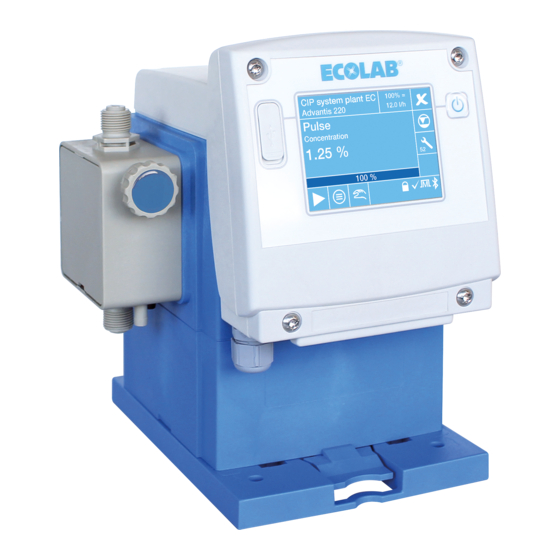
Description of the pump Description of the pump Fig. 5: Structure ‘EcoAdd’ Rotary operating device Type plate ON/OFF button Mains cable bushing / Mains connection USB port Suction connection / suction valve Input display (touchscreen) Pump head Cable bushings and connections behind the display... -
Page 37: Connection Sockets / Cable Bushings
Description of the pump Connection sockets / cable bushings Fig. 6: Connections ‘EcoAdd’ Mains cable bushing / Mains connection Level monitoring (suction lance connection) 2-5 Cable bushings to the main board with terminals Ä Chapter 6.3.4.1 ‘Terminal assignment’ The connection is described in on page 52 . -
Page 38: Assembly, Installation, Modification And Upgrades
Assembly, installation, modification and upgrades Assembly, installation, modification and upgrades Personnel: Manufacturer Mechanic Service personnel Specialist General information and safety NOTICE! General instructions for installation and assembly: – The pump must be installed at an easily accessible, frost-protected location. – The ambient conditions indicated in the "Technical Data" must be complied with. -
Page 39: Assembly Variants
Assembly, installation, modification and upgrades CAUTION! – Setup, installation and mounting work are to be performed exclusively by authorised, trained and approved experts in compliance with prevailing general guidelines and local regulations. – Special measures and protective equipment for metering hazardous or aggressive chemicals are not listed here. -
Page 40: Stand Mounting Or Floor Mounting
Assembly, installation, modification and upgrades 6.2.1 Stand mounting or floor mounting Fig. 9: Preparations for stand mounting Turn mounting plate over Only fastening elements with the code 1 (Fig. 9, pos. 2) are used for stand mounting. Insert fastening elements from behind into the four openings marked "table" (= table/stand mounting) and engage into position. -
Page 41: Wall Mounting
Assembly, installation, modification and upgrades 6.2.2 Wall mounting Fig. 10: Preparations for wall mounting Turn mounting plate over. For wall mounting, fastening elements with the code 2 (Fig. 10, pos. 3) and with code 1 (Fig. 10, pos. 2) are used. Insert fastening elements (labelled: 1, Fig. -
Page 42: Conversion - Change From Stand Mounting To Wall Mounting
Assembly, installation, modification and upgrades 6.2.3 Conversion - change from stand mounting to wall mounting To allow the pump to be adjusted to the site conditions, you can use the pump in either stand-mounted or wall-mounted form. Fig. 11: Change from stand mounting (upright, e.g. floor, bracket or canister) to wall mounting (hanging). Remove the connector lines as far as necessary (hydraulically and electrically). -
Page 43: Hydraulic Installation
Assembly, installation, modification and upgrades 6.3.1 Hydraulic installation Personnel: Mechanic Service personnel Specialist Installation diagram 1 Overflow valve 2 Pressure control valve 3 Option: Multi-function valve (MFV) 4 Suction pipe or bottom admission valve D Pressure valve P Pump head S Suction valve Overflow valve and and pressure control valves , (Pos. -
Page 44: Installation Examples
Assembly, installation, modification and upgrades 6.3.2 Installation examples Installation examples - Hydraulic installation With media that tend towards sedimentation, the base suction valve or the foot valve of the suction line or suction lance must be mounted above the expected sludge layer. - Page 45 Assembly, installation, modification and upgrades Installation example 3 1 Injection valve / metering valve 2 External release 3 Solenoid valve 4 Pressure control valve When metering in pipes with a vacuum, a pressure control valve (pos. 4) is to be installed in the metering line. A pressure-retention valve or metering valve is not a shut-off device which is absolutely tight sealing.
-
Page 46: Connection Of The Suction And Pressure Lines (Metering Lines)
Assembly, installation, modification and upgrades Installation example 6 The suction line must always be installed sloping upwards towards the metering pump. Installation example 7 A metering monitoring instrument, such as an oval gear motor (pos. 1), or flow monitor, must be installed into the metering line downstream of the overflow valve and upstream of a pressure control valve or metering valve. -
Page 47: Hose Connection With Support Sleeve And Clamping Ring
Assembly, installation, modification and upgrades 6.3.3.1 Hose connection with support sleeve and clamping ring Fig. 12: Pipe and hose connection with integrated support sleeve Pipe or hose connection O-ring Union nut Suction valve, pressure valve Clamping ring A1 Pipe or hose attached Slip-on bushing A2 Target state after assembly Female connector... -
Page 48: Pipe And Hose Connection With Tapered Part
Assembly, installation, modification and upgrades 6.3.3.2 Pipe and hose connection with tapered part Fig. 13: Pipe/hose connection with tapered part Hose O-ring Union nut Suction valve, pressure valve Clamping piece A1 Pipe or hose attached Tapered part B1 Valve connection: Target state after assembly Cut hose (1) straight. -
Page 49: Pipe And Hose Connection With Attachment Nipple And Hose Clamp
Assembly, installation, modification and upgrades 6.3.3.3 Pipe and hose connection with attachment nipple and hose clamp Fig. 14: Pipe and hose connection with attachment nipple and hose clamp Detail/Section: Illustration of individual part Suction valve, pressure valve Hose Hose clamp Union nut A1 Pipe or hose attached Tapered part... -
Page 50: Hose Connection With Weld-On Joint
Assembly, installation, modification and upgrades 6.3.3.4 Hose connection with weld-on joint Fig. 15: Pipe and hose connection with female coupling Weld-on joint Suction valve, pressure valve Pipe or hose A1 Pipe or hose in the weld-on joint Union nut B1 Valve connection: Target state after assembly O-ring Weld the weld-on connection (1) to the hose connection. -
Page 51: Electrical Installation
Risk of electric shock Pay attention to disconnect the power supply immediately and to secure against accidental switch-on! Fig. 16: Electrical installation ‘EcoAdd’ Remove all four housing screws. Remove the front cover. To connect additional external enable signals, route the connector lines through the clamping cube. -
Page 52: Terminal Assignment
Only skilled personnel are authorised to carry out all changes to the terminal assignment. Contact our Customer Service if you have any queries or need assistance. Fig. 17: Terminal assignment ‘EcoAdd’ L1 Mains phase (live conductor) 15 Diaphragm monitoring: Diaphragms... -
Page 53: Language Selection
The language selection screen is displayed in English because this makes it easiest to select from the languages available and English is widely understood. Fig. 18: Language selection after starting the ‘EcoAdd pump’ Language selection after switching on the pump for the first time: ‘Press the ON/OFF button’... -
Page 54: Modification/Upgrade
Assembly, installation, modification and upgrades Modification/upgrade 6.5.1 Modification - turning the pump head To allow the pump to be adjusted to the site conditions, it is possible to turn the control unit (operating unit/upper part of the pump). DANGER! Risk of electric shock Pay attention to disconnect the power supply immediately and to secure against accidental switch-on! Fig. -
Page 55: Upgrading Of The Ecoadd With A Bluetooth Interface
Assembly, installation, modification and upgrades 6.5.2 Upgrading of the EcoAdd with a Bluetooth interface To be able to monitor and control the pump using a suitable smartphone, you must fit a Bluetooth PCB. The pump can be ordered both with and without Bluetooth PCB. The Bluetooth function can also be upgraded: Ä... -
Page 56: Control / Software
Operator General information: – The control unit / software described in this section relates exclusively to the pump type ‘EcoAdd’ . – The overviews shown of the menu levels only appear in the first setting level. – The following screens show example displays for a pump with a capacity of 11 l/h. -
Page 57: Start Screen
Control / software Start Screen When the pump is switched on, the following is displayed for about five seconds: Specific pump key Specific production code, Version of the software used Supply voltage of the pump Used materials for pump head an, diaphragm, sealings and valves. -
Page 58: Cleaning The Touch-Sensitive Control Panel
Control / software 7.3.1 Cleaning the touch-sensitive control panel CAUTION! It is advisable to use a microfibre cloth to clean the touch-sensitive control panel. – Do not use any unsuitable detergents so as to avoid damaging the surface of the control panel. –... -
Page 59: Operating Buttons
Control / software 7.3.2 Operating buttons Symbol Description / Function "Main menu" button: Call up the main menu. "Menu" button: Call up the higher level menu. "Next" button: Call up / show the next setting display. "Plus" button: Adjustment of a value into the positive range. "Minus"... -
Page 60: Scroll Bars, Radio Buttons, Selection Fields, Number And Text Input
Control / software 7.3.3 Scroll bars, radio buttons, selection fields, number and text input Show menu options on subsequent pages with the scroll bar: Fig. 22: Example: Scroll bars The scroll bar (white bar, pos. 2) can be moved to call up menu entries that cannot be displayed on a page. - Page 61 Control / software Input numbers: Fig. 25: Example: Input field Numbers can be input in fields which are highlighted in dark colours (pos. 2). To select a field for input, touch the required input field. Fields which are not selected (pos. 1) are shown with the same background as the actual display.
-
Page 62: Display View During Ongoing Operation (Example)
Control / software Display view during ongoing operation (example) Fig. 27: Operating indicator (example) Pos. Designation Pump name Ä Chapter 7.9.1 ‘Pump name’ on page 84 Maximum metering output in l/h (depending on the selected metering mode) Ä Chapter 7.7 ‘Metering mode’ on page 67 Metering mode (s, m, l, v) Ä... -
Page 63: Symbols In Operating Mode
Control / software 7.4.1 Symbols in operating mode Symbol Description Metering mode and signal to indicate that the pump is running With every stroke of the pump, the display background flashes in the top right. The letter shown represents the metering mode that is currently selected: = standard, = medium;... - Page 64 Control / software Symbol Description Metering release Metering release is activated. Calibration Notice to perform a calibration of the pump! Oval gear meter - OGM An oval gear meter (OGM) is connected to the pump. Select Batch Display of the [Select Batch]operation Ä...
-
Page 65: Menu Structure
Control / software Menu structure If you have activated an [access code] , note the following: Ä Chapter 7.6.2 ‘Open the main menu with the access code activated’ on page 67. Fig. 28: Menu structure Rev. 2-05.2018... -
Page 66: Main Menu
Control / software Main menu If the [access code] is enabled , please note the following: Ä Chapter 7.6 ‘Main menu’ on page 66. 7.6.1 Open the main menu Fig. 29: Calling up the main menu without an access code [Open main menu] by pressing the [Menu button] ð... -
Page 67: Open The Main Menu With The Access Code Activated
Control / software 7.6.2 Open the main menu with the access code activated Fig. 30: Calling up the main menu with an access code [Open main menu] by pressing the [Menu button] ð The screen switches to query the [access code]. The activated [access code] is shown by the padlock symbol ! [access code] using the scroll bar (range: A-Z, 0-9, and various special characters). - Page 68 Control / software Type 00510x: Suction min. metering Metering Max. stroke Stroke stroke stroke output frequency volume Duration duration at 100% Metering 100 % mode Display (¦) Standard 5 l/h 155 / min 190 ms Medium 4,17 l/h 141 / min 228 ms 0,53 l/h 197 ms...
- Page 69 Control / software Type 05010M: Suction min. metering Metering Max. stroke Stroke stroke stroke output frequency volume Duration duration at 100% Metering 100 % mode Display (¦) Standard 54 l/h 159 / min 185 ms Medium 45 l/h 145 / min 222 ms 5,8 ml 192 ms...
- Page 70 Control / software Fig. 31: Overview: metering mode Factory setting: Standard Selection of the metering mode: [Open main menu] by pressing the [Menu button] Ä Chapter 7.6 ‘Main menu’ on page 66. Ä Chapter 7.9 ‘Overview - Configuration’ on page 83 [Configuration menu] : [Metering mode] - select.
-
Page 71: Metering Mode] [Select V-Variable]
Control / software 7.7.1 [Metering mode] [Select V-variable] Fig. 32: Metering mode: "V-variable" [Metering mode] - [Select V-variable] - setting: [Open main menu] by pressing the [Menu button] Ä Chapter 7.6 ‘Main menu’ on page 66. Ä Chapter 7.9 ‘Overview - Configuration’ on page 83 [Configuration menu] : [Metering mode] - select. -
Page 72: Operating Mode
Control / software Operating mode Selecting the operating mode sets whether the pump is operated using internally set values (Manual, Timer) or if an external signal determines the metering rate (pulse, current). Fig. 33: Overview: Operating mode Factory setting: Manual [Operating mode] - select: [Main menu] : Ä... -
Page 73: Operating Mode] [Manual]
Control / software 7.8.1 [Operating mode] [Manual] With the [Operating mode] [Manual] the required metering rate is set manually. After switching on, the pump runs at the metering frequency corresponding to the selected metering rate. The metering rate can also be changed in ongoing operation: Ä... -
Page 74: Operating Mode] [Pulse] - Concentration
Control / software Terminal assignment when using a water meter: Fig. 35: Terminal assignment: ‘Pulse’ Terminal assignment: "floating contact" Terminal assignment: "electronic switch" 7.8.2.1 [Operating mode] [Pulse] - Concentration The pulse interval (ml, l / pulse) for the flow meter being used and the concentration of the metering solution in % must be entered here first of all. - Page 75 Control / software [Operating mode] - [Pulse] - select. [Press the Next button] ð Screen change for setting: ‘Pulse interval’ . Enter pulse interval (ml, l / pulse) of the flowmeter being used. Select the field for entering the value after the decimal point. ð...
-
Page 76: Operating Mode] [Pulse] - Quantity
Control / software 7.8.2.2 [Operating mode] [Pulse] - Quantity Fig. 37: Operating mode: Pulse Ä Chapter 7.6 ‘Main menu’ on page 66 [Main menu] : [Operating mode] - [Pulse] - select. [Press the Next button] ð Screen change for setting: ‘Pulse interval’ . DO NOT enter a pulse interval, or set pulse interval to 0! To do this, set the decimal places to 0 using the scrollbar. -
Page 77: Operating Mode] [Power]
Control / software 7.8.3 [Operating mode] [Power] In the ‘Power’ operating mode the metering capacity of the pump is determined by the level of the incoming standardised current signal (0/4-20 mA). Example: Input signal 4 - 20 mA = metering capacity 0 - 100% Terminal assignment: Fig. - Page 78 Control / software Fig. 39: operating mode: Power [Operating mode] - [Power] - setting: Ä Chapter 7.6 ‘Main menu’ on page 66 [Main menu] : [Operating mode] - [Power] - select. [ Press the Next button] ð Screen change for the power setting: ‘Select a power range’...
-
Page 79: Operating Mode] [Power] [Variable]
Control / software 7.8.3.1 [Operating mode] [Power] [variable] Fig. 40: [Operating mode] [Power] [variable] [Operating mode] - [Power] - setting: Ä Chapter 7.6 ‘Main menu’ on page 66 [Main menu] : [Operating mode] - [Power] - select. [ Press the Next button] ð... -
Page 80: Operating Mode] [Timer]
Control / software 7.8.4 [Operating mode] [Timer] In the Timer operating mode, the runtime and standstill times of the pumps are determined by the adjustable time spans. There are two different program types for selection here. In the seven-day programme, up to seven metering times can be set per weekday. Switch-on time, metering duration and metering capacity can be individual selected for each metering time. - Page 81 Control / software Ä Chapter 7.6 ‘Main menu’ on page 66 [Main menu] : [Operating mode] - [Timer] - select. [Press the Next button] ð Screen change to the selection of the timer interval (weekly programme) [Seven-day programme] - select. ð...
-
Page 82: Operating Mode] [Timer] [Select Interval Programme]
Control / software 7.8.4.2 [Operating mode] [Timer] [Select interval programme] Fig. 42: Operating mode: [Timer] [Select interval programme] [Operating mode] - [Timer] [Select interval programme]- setting: Ä Chapter 7.6 ‘Main menu’ on page 66 [Main menu] : [Timer] [Select interval programme] - select. [Press the Next button] ð... -
Page 83: Overview - Configuration
Control / software Overview - Configuration Fig. 43: Overview: Configuration Selection of the configuration: Ä Chapter 7.6 ‘Main menu’ on page 66 [Call up Main menu] : [Select configuration] . ð The screen switches to the overview: [Configuration]. Select the configuration setting (system parameters). By pressing the button, you can return to the [Main menu]. -
Page 84: Pump Name
Control / software 7.9.1 Pump name Fig. 44: Configuration: Pump name Factory setting: No name allocated. [Set the pump name:] Call up the [Main menu]: Ä Chapter 7.6 ‘Main menu’ on page 66 [Configuration] selection: Ä Chapter 7.9 ‘Overview - Configuration’ on page 83 Select [pump name.] ð... -
Page 85: Selecting The Date/Time
Control / software 7.9.2 Selecting the date/time Fig. 45: Configuration: Date/time [Selecting the date/time] - setting: Ä Chapter 7.6 ‘Main menu’ on page 66 [Main menu] : Ä Chapter 7.9 ‘Overview - Configuration’ on page 83 [Configuration menu] : [Selecting the date/time] - select. ð... -
Page 86: Language
7.9.3 Language 7.9.3.1 Language selection The ‘EcoAdd’ is set to display a language selection screen the first time it is switched on to ensure that the operating language is suitable for the on-site operating personnel. The language selection screen is displayed in English because this makes it easiest to select from the languages available and English is widely understood. -
Page 87: Reset The Language To German Or To Another Language
Control / software 7.9.3.2 Reset the language to German or to another language Fig. 47: Language overview [Language] - setting: Ä Chapter 7.6 ‘Main menu’ on page 66 [Main menu] : [Configuration menu] : Ä Chapter 7.9 ‘Overview - Configuration’ on page 83 Menu item [Language] - select ð... -
Page 88: Access Code
User with the [Access code] ‘Operator (O)’ have fewer authorisations in the setting options. The [Access code] for ‘Administrator (A)’ has complete access to all the functions of ‘EcoAdd’ pump enabled for the user. – In the [Configuration] first the entry of the [access codes] of ‘Administrator (A)’... - Page 89 Control / software Fig. 48: Configuration: Access code Factory setting: No access code [Set Access code] : Ä Chapter 7.6 ‘Main menu’ on page 66 [Call up Main menu] : Ä Chapter 7.9 ‘Overview - Configuration’ on page 83 [Select Configuration] : [Access code] .
-
Page 90: Incorrect [Access Code]
What to do if you forget the access code Reset the password: If you forget the access code, you can contact Ecolab Service to request an access code with which to “unlock” the pump and set a new code. IMPORTANT: –... -
Page 91: Unit
Control / software 7.9.5 Unit Fig. 50: Configuration: Unit Factory setting: Litres [Unit] - setting: [Main menu] : Ä Chapter 7.6 ‘Main menu’ on page 66 [Configuration menu] : Ä Chapter 7.9 ‘Overview - Configuration’ on page 83 Scroll up to [Unit] using the scrollbar along the right edge of the screen. [Unit] - select. -
Page 92: Autostart
Control / software 7.9.6 Autostart The function [Autostart option] determines whether the pump is set to "Pause" when the mains connection is re-established following a power cut or if the pump should immediately start running again in the set operating mode. CAUTION! The operator of the pump is responsible for avoiding the risk of an accidental startup of the pump after the power is reconnected using suitable higher level... -
Page 93: Metering Enable
Control / software 7.9.7 Metering enable With the metering enable function activated, the pump only runs when an external enable contact is closed on terminal 20 and terminal 21 (see Ä Chapter 6.3.4.1 ‘Terminal Ä Chapter 8.2.1 ‘Operating mode [Manual] (with ‘metering assignment’... -
Page 94: Select Empty Signal
Control / software 7.9.8 Select empty signal The empty signal describes the type of empty signal. The "Empty signal contact" selection defines whether or not the empty signal is triggered with an open contact or closed contact. A suitable suction pipe must be connected to the empty signal input on the Ä... -
Page 95: Acknowledge Automatically
Control / software 7.9.8.1 Acknowledge automatically: The pump switches to Pause on empty signal and the empty signal symbol is displayed in . The suction pipe issues a "Full" signal to the pump after a container change and the container change is detected and accepted without further confirmation. Fig. -
Page 96: Acknowledge Manually
Control / software 7.9.8.2 Acknowledge manually: The pump switches to Pause on empty signal and the empty signal symbol is displayed in . After pressing the red empty signal symbol, the container change must first be approved on the screen and the suction pipe can then be moved to a new container. Fig. -
Page 97: Alarm Relay
Control / software 7.9.9 Alarm relay The functional method of the alarm output and the response of the pump on an alarm can be defined here. The alarm relay can be used to display when the pump goes to a stop condition, in other words if it is switched off accidentally via the Display button. -
Page 98: Dosing Chemical
Control / software 7.9.10 Dosing chemical This setting provides the option to define a metering chemical being used. Overview Fig. 57: Configuration: Metering chemical Factory setting: No details The following selection options are available: Ä Chapter 7.9.10.1 ‘No entry’ on page 98 Ä... -
Page 99: Manual Input (Manual)
Control / software 7.9.10.2 Manual input (manual) Fig. 59: Configuration: Metered chemical - Manual Set [Manual:] Ä Chapter 7.6 ‘Main menu’ on page 66 Call up the[Main menu]: Ä Chapter 7.9 ‘Overview - Configuration’ on page 83 Select [Configuration]: Scroll up to [Dosing chemical] using the scrollbar along the right edge of the screen. Select [Dosing chemical]. -
Page 100: Chemical Selection From An Integrated Database
If no selection is made for the pump, in addition to ‘No details’ and ‘Manual’ , the use of a database can be applied, however, please contact the customer service department at Ecolab. This description displays the potential version with database. - Page 101 Control / software Select a chemical from the database: Ä Chapter 7.6 ‘Main menu’ on page 66 [Main menu] : [Configuration menu] : Ä Chapter 7.9 ‘Overview - Configuration’ on page 83 Scroll up to [Metering chemical] using the scrollbar along the right edge of the screen.
-
Page 102: Service Interval
Control / software 7.9.11 Service interval The service interval of a pump can be set or adjusted. NOTICE! When a metering chemical is selected from the database, a resistance check of the pump materials is stored in connection with the chemicals and the corresponding service interval is set automatically. -
Page 103: Service Interval] - [Variable]
Control / software 7.9.11.1 [Service interval] - [variable] Fig. 62: Service interval - variable After selecting [service interval] - [variable] the setting is saved by clicking the button. The screen switches to the Configuration overview. [Service interval] - select: Ä Chapter 7.6 ‘Main menu’ on page 66 [Main menu] : [Configuration menu] : Ä... -
Page 104: Select Batch
Control / software 7.9.12 Select Batch Connect the zero-potential contact to the corresponding input and GND. – Do not connect any external voltages! – Voltage-free contact (relay) – max. external voltage: 230 V, AC/DC, max. 3 A. – Reserve signal: Contact closed / opened approx. 500 ms With batch mode activated, a previously defined rate is metered by a start signal on Ä... -
Page 105: Select Batch] - [No Batch Metering]
Control / software [Select Batch] - select: Ä Chapter 7.6 ‘Main menu’ on page 66 [Main menu] : [Configuration menu] : Ä Chapter 7.9 ‘Overview - Configuration’ on page 83 Use the scrollbar to scroll to the [Select Batch] menu option. [Select Batch] - select. -
Page 106: Select Batch] - [Initial Preparation]
Control / software 7.9.12.2 [Select Batch] - [Initial preparation] Fig. 65: Charge - [Initial preparation] Ä Chapter 7.6 ‘Main menu’ on page 66 [Main menu] : Ä Chapter 7.9 ‘Overview - Configuration’ on page 83 [Configuration menu] : Use the scrollbar to scroll to the [Select Batch] menu option. [Select Batch] - select. -
Page 107: Select Batch] - [Initial Concentration]
Control / software 7.9.12.3 [Select Batch] - [Initial concentration] Fig. 66: Charge - [Initial preparation] [Main menu] : Ä Chapter 7.6 ‘Main menu’ on page 66 [Configuration menu] : Ä Chapter 7.9 ‘Overview - Configuration’ on page 83 Use the scrollbar to scroll to the [Select Batch] menu option. [Select Batch] - select. -
Page 108: Container Size
Control / software 7.9.13 Container size The fill volume of the container is given under container size. If a value is set here for pumps without Bluetooth PCB, a "Canister" (Fig. 67, pos. B) is displayed on the operating screen instead of the empty signal symbol (Fig. 67, pos. A). A calculated fill level is displayed here symbolically based on the last container change. -
Page 109: Oval Gear Meter
Control / software 7.9.14 Oval gear meter The oval gear meter permits a "true" quantity calculation that is active when PLUS an oval gear motor, type: OGM (see accessories) has been connected. To assemble the OGM PLUS , disconnect the power supply and connect it to Ä... -
Page 110: Oval Gear Meter] - Setting
Control / software 7.9.14.1 [Oval gear meter] - setting Fig. 68: ‘Configuration’ ‘Oval gear meter’ [Main menu] : Ä Chapter 7.6 ‘Main menu’ on page 66 [Configuration menu] : Ä Chapter 7.9 ‘Overview - Configuration’ on page 83 Use the scrollbar to scroll to the [Oval gear meter] menu option. [Oval gear meter] - select. -
Page 111: Metering Monitoring
Control / software 7.9.14.1.1 Metering monitoring Fig. 69: Configuration: Metering monitoring Factory setting: without metering monitor Selection of the [Metering monitoring]: Ä Chapter 7.6 ‘Main menu’ on page 66 [Main menu] : [Configuration menu] : Ä Chapter 7.9 ‘Overview - Configuration’ on page 83 Use the scrollbar to scroll to the [Oval gear meter] menu option. -
Page 112: Metering Controller
Control / software 7.9.14.1.2 Metering controller Fig. 70: Configuration: Metering controller Factory setting: No metering controller [Metering controller] - select: [Main menu] : Ä Chapter 7.6 ‘Main menu’ on page 66 [Configuration menu] : Ä Chapter 7.9 ‘Overview - Configuration’ on page 83 Use the scrollbar to scroll to the [Oval gear meter] menu option. -
Page 113: Max. Metering Phase
Control / software 7.9.14.1.3 Max. metering phase Fig. 71: Configuration: Max. metering phase [Max. metering phase] - select: [Main menu] : Ä Chapter 7.6 ‘Main menu’ on page 66 Ä Chapter 7.9 ‘Overview - Configuration’ on page 83 [Configuration menu] : Use the scrollbar to scroll to the [Oval gear meter] menu option. -
Page 114: Diaphragm Brakeage
Control / software 7.9.15 Diaphragm brakeage An automatic monitoring of the pump diaphragm can be switched on or off under ‘Diaphragm brakeage’ . Requirements: This function can only be used when a pump head of 30 l/h, 50 l/h or 120 l/h size is installed on the pump with the respective diaphragm protection sensor. -
Page 115: Import/Export Of The Configuration
On the USB stick, create the directory ‘ECOADD’ . In the ‘ECOADD’ directory, create a subdirectory with the name ‘EXPORT’ . In the ‘ECOADD’ directory, create a subdirectory with the name ‘IMPORT’ . -
Page 116: Importing And Updating The Configuration
ð The screen displays the configuration files located on the USB stick. It displays only configuration files located on the USB stick at the path: /ECOADD/IMPORT ! Select the desired configuration file. ð The configuration file is loaded onto the pump control. -
Page 117: Exporting A Configuration
Once the export process is complete, the screen switches back to the menu for importing and exporting the configuration. Pressing the button returns to the [Main menu]. Pressing the button returns to the [Operating display]. The exported configuration is located on the USB stick at the path: /ECOADD/EXPORT Rev. 2-05.2018... -
Page 118: Calibration
Control / software 7.10 Calibration The metering pump is calibrated at the site to the flow rate of the corresponding pump type at nominal pressure. The corresponding flow rate and the nominal pressure is given in the technical data in the operating manual. We recommend performing another calibration on the pump again after installation and thus to adjust it to the on-site operating and ambient conditions. - Page 119 Control / software [Calibration] - start: Ä Chapter 7.6 ‘Main menu’ on page 66 [Main menu] : [Configuration menu] : Ä Chapter 7.9 ‘Overview - Configuration’ on page 83 Scroll up to [Calibration] using the scrollbar along the right edge of the screen. [Calibration] - select ð...
-
Page 120: Operating Data
Control / software 7.11 Operating data Here all operating data since commissioning or since the last reset of the metering pump can be retrieved. All operating data is stored for a maximum of 1 year. Fig. 77: Operating data Rev. 2-05.2018... -
Page 121: Info
Control / software Ä Chapter 7.6 ‘Main menu’ on page 66 [Main menu] : Ä Chapter 7.9 ‘Overview - Configuration’ on page 83 [Configuration menu] : Scroll up to [Operating data] using the scrollbar along the right edge of the screen. [Operating data] - select ð... -
Page 122: Internal Storage
Fig. 79: Internal memory management of EcoAdd The memory status is visible only when one of the three storage types is at least 75% filled. Then at least one of the three fields is orange (pos. 1). After 95% of the storage capacity, the colour of the corresponding segment changes to red (pos. -
Page 123: Commissioning
Commissioning Commissioning Personnel: Manufacturer Production supervisor Service personnel Specialist Operator DANGER! – Initial commissioning may only be performed by authorised personnel with experience of metering system operation. – Initial commissioning must be documented and the settings made must be recorded in the log. –... -
Page 124: Initial Commissioning
Commissioning DANGER! Electrical dangers Electrical hazards are marked by the symbol opposite. Work in these areas may only be carried out by trained personnel with the appropriate authorisation. Initial commissioning Install the mounting plate and pump in the required location and installation scenario. Ä... -
Page 125: Connection And Set-Up Examples
Commissioning Connection and set-up examples 8.2.1 Operating mode [Manual] (with ‘metering enable’ ) Terminal assignment: Fig. 80: Terminal assignment: Floating contact Step one: Select operating mode in the software: Fig. 81: Select the operating mode [Main menu] Press the button. ð... - Page 126 Commissioning Step two: Activate dosing release Fig. 82: Software setting: ‘Dosing release’ [Main menu] Press the button. ð The ‘Main menu’ screen is displayed. [Configuration menu] - select. ð Menu [Configuration menu] is displayed. Use the scrollbar to go to the [Dosing release] using the scrollbar along the right edge of the screen.
-
Page 127: Operating Mode [Pulse]
Commissioning Step three: Set the metering rate/capacity in litres The following screens show example displays for a pump with capacity of 11 l/h. Specifications and information shown will differ for other pump sizes. Fig. 83: Set the metering rate/capacity in litres In the [Operating display] press the displayed ‘capacity in litres’... - Page 128 Commissioning Terminal assignment when using a water meter: Fig. 84: Terminal assignment: ‘Pulse’ Terminal assignment: "floating contact" Terminal assignment: "electronic switch" Software setting: Fig. 85: Software setting: ‘Pulse’ Rev. 2-05.2018...
- Page 129 Commissioning [Main menu] Press the button. ð The ‘Main menu’ screen is displayed. [Operating mode] - select. ð The screen for setting the [Operating mode] is displayed. [Pulse] - select. [ Press the Next button] ð Screen for setting the ‘pulse interval’ is displayed. Enter the quantity in litres (before the decimal point) using the scrollbar.
-
Page 130: Operating Mode] [Power]
Commissioning [Operating Mode] [Power] In the operating mode ‘Power’ the metering capacity of the pump is determined by the level of the incoming standardised current signal (0/4-20 mA). Example: Input signal 4 - 20 mA = metering capacity 0 - 100% Terminal assignment: Fig. - Page 131 Commissioning Step 2: [Operating Mode] - [Power] : Fig. 87: Operating Mode: Power Ä Chapter 7.6 ‘Main menu’ on page 66 [Call up Main menu] : [Select Operating Mode] - [Power] . [ Press the Next] button. ð Screen change for the current setting: ‘Select the current range’...
-
Page 132: Operating Mode] [Power] [Variable]
Commissioning 8.3.1 [Operating mode] [Power] [variable] Fig. 88: [Operating mode] [Power] [variable] [Operating mode] - [Power] - setting: Ä Chapter 7.6 ‘Main menu’ on page 66 [Main menu] : [Operating mode] - [Power] - select. [ Press the Next button] ð... -
Page 133: Calibration On Initial Start-Up
Commissioning Calibration on initial start-up The metering pump is calibrated at the site to the flow rate of the corresponding pump type at nominal pressure. The corresponding flow rate and the nominal pressure is given in the technical data in the operating manual. We recommend performing another calibration on the pump again after installation and thus to adjust it to the on-site operating and ambient conditions. - Page 134 Commissioning Perform calibration Fig. 90: Software setting: ‘Calibration’ [Calibration] - start: [Main menu] Press the button. ð The [Main menu] is displayed. [Calibration] - select. ð The screen for starting [Calibration] is displayed. [Start] - press. ð Screen changes to the ‘calibration step 1’ . Calibration step 1 runs automatically.
-
Page 135: Operation
Personnel: Production supervisor Operator Specialist Switching the pump on and off Fig. 91: EcoAdd Touchscreen USB connection for data transfer On/off button Input and settings are solely carried out via the touchscreen (Fig. 91, Pos. 1). The pump is switched on via the ‘ON / OFF button’... -
Page 136: Display View During Ongoing Operation (Example)
Operation Display view during ongoing operation (example) Fig. 92: Operating indicator (example) Pos. Designation Pump name Ä Chapter 7.9.1 ‘Pump name’ on page 84 Maximum metering output in l/h (depending on the selected metering mode) Ä Chapter 9.7.1 ‘Metering mode’ on page 144 Metering mode (s, m, l, v) Ä... -
Page 137: Symbols In Operating Mode
Operation 9.3.1 Symbols in operating mode Symbol Description Metering mode and signal to indicate that the pump is running With every stroke of the pump, the display background flashes in the top right. The letter shown represents the metering mode that is currently selected: = standard, = medium;... - Page 138 Operation Symbol Description Metering release Metering release is activated. Calibration Notice to perform a calibration of the pump! Oval gear meter - OGM An oval gear meter (OGM) is connected to the pump. Select Batch Display of the [Select Batch]operation Ä...
-
Page 139: Setting Or Changing The Pump Capacity In L
Operation Setting or changing the pump capacity in L The following screens show example displays for a pump with capacity of 11 l/h. Specifications and information shown will differ for other pump sizes. Fig. 93: Changing the pump capacity in L during ongoing operation Set or change the pump capacity in L: On the operation screen, press the displayed ‘capacity in L’... -
Page 140: Changing A Container - Empty Signal
Operation Changing a container - Empty signal Chemical hazards (dosing medium/active substance) DANGER! Risk of injury to the skin and eyes caused by the chemical used (dosing medium). – Read the enclosed safety data sheet carefully before using the dosing medium. -
Page 141: Container Change With The Preset (Acknowledge Auto.)
Operation 9.5.1 Container change with the preset (acknowledge auto.) Fig. 94: Container change for the preset (acknowledge auto.) If the metering pump detects an empty container via a connected suction pipe with integrated empty signal detection, this is displayed in red via the empty signal symbol If the container size has been set as described in Ä... -
Page 142: Container Change With The Preset (Acknowledge Man.)
Operation 9.5.2 Container change with the preset (acknowledge man.) Fig. 95: Empty signal: Changing a container In the operating screen, press the ‘empty signal indicator’ To access the settings, press and hold the displayed ‘empty signal’ for around 3 seconds. If a password prompt is displayed, the access code must be entered Ä... -
Page 143: Confirm The Pump Service
Operation Confirm the pump service Provided that an access code has been set in the pump, the pump servicing can only be done with the access authorisation ‘Administrator’ ! Symbol Description of service displays Service info with blue background: No servicing required Service info with orange background: Advance notice of a servicing Service info with a red background: Servicing overdue Fig. -
Page 144: Changeover 'Metering Mode
Operation Changeover ‘Metering mode’ 9.7.1 Metering mode Selecting a corresponding [Metering mode] ( / / / ) makes it possible to extend the suction duration per stroke (suction stroke duration) and thus adjust the metering to high product viscosities or challenging suction conditions. This extension of the suction stroke duration simultaneously results in a reduction in the max. - Page 145 Operation Type 03003S: Suction min. metering Metering Max. stroke Stroke stroke stroke output frequency volume Duration duration at 100% Metering 100 % mode Display (¦) Standard 30 l/h 155 / min 190 ms Medium 25 l/h 141 / min 228 ms 3,4 ml 197 ms 20 l/h...
- Page 146 Operation – Switching between the metering modes means that the diaphragm metering pump must be re-calibrated! The calibration symbol C! is displayed on the display of the operating level. – Once the automatic [Calibration] has been correctly carried out, the symbol C! is hidden in the operating level again! –...
-
Page 147: Metering Mode] [Select V-Variable]
Operation 9.7.1.1 [Metering mode] [Select V-variable] Fig. 98: Metering mode: "V-variable" [Metering mode] - [Select V-variable] - setting: [Open main menu] by pressing the [Menu button] Ä Chapter 7.6 ‘Main menu’ on page 66. Ä Chapter 7.9 ‘Overview - Configuration’ on page 83 [Configuration menu] : [Metering mode] - select. -
Page 148: Changeover 'Operating Mode
Operation Changeover ‘Operating Mode’ 9.8.1 Operating Mode Selecting the operating mode decides whether the pump is operated using internally set values (Manual, Timer) or if an external signal determines the metering rate (pulse, current). Fig. 99: Overview: Operating mode Factory setting: Manual [Select Operating Mode] : Ä... -
Page 149: Operating Mode] [Manual]
Operation 9.8.1.1 [Operating Mode] [Manual] With the [Operating mode] [Manual] the required metering rate is set manually. After switching on, the pump runs at the metering frequency corresponding to the selected metering rate. The metering rate can also be changed in ongoing operation: Ä... -
Page 150: Operating Mode] [Pulse] - Concentration
Operation Terminal assignment when using a water meter: Fig. 101: Terminal assignment: ‘Pulse’ Terminal assignment: "floating contact" Terminal assignment: "electronic switch" 9.8.1.2.1 [Operating Mode] [Pulse] - Concentration The pulse interval (ml, l / pulse) for the flow meter being used and the concentration of the metering solution must be first entered here in %. - Page 151 Operation [Select Operating Mode] - [Select Pulse] . [Press the Next] button. ð Screen change for setting: ‘Pulse interval’ . Enter pulse interval (ml, l / pulse) of the flowmeter being used. Select the field for entering the value after the decimal point. ð...
-
Page 152: Operating Mode] [Pulse] - Quantity
Operation 9.8.1.2.2 [Operating Mode] [Pulse] - Quantity Fig. 103: Operating Mode: Pulse Ä Chapter 7.6 ‘Main menu’ on page 66 [Call up Main menu] : [Select Operating Mode] - [Pulse] . [Press the Next] button. ð Screen change for setting: ‘Pulse interval’ . Do NOT enter ANY pulse interval, or set the pulse interval to 0! For this, set 0 in the place before the decimal point using the scrollbar. -
Page 153: Operating Mode] [Power]
Operation 9.8.1.3 [Operating mode] [Power] In the ‘Power’ operating mode the metering capacity of the pump is determined by the level of the incoming standardised current signal (0/4-20 mA). Example: Input signal 4 - 20 mA = metering capacity 0 - 100% Terminal assignment: Fig. - Page 154 Operation Fig. 105: operating mode: Power [Operating mode] - [Power] - setting: Ä Chapter 7.6 ‘Main menu’ on page 66 [Main menu] : [Operating mode] - [Power] - select. [ Press the Next button] ð Screen change for the power setting: ‘Select a power range’...
-
Page 155: Operating Mode] [Power] [Variable]
Operation 9.8.1.3.1 [Operating mode] [Power] [variable] Fig. 106: [Operating mode] [Power] [variable] [Operating mode] - [Power] - setting: [Main menu] : Ä Chapter 7.6 ‘Main menu’ on page 66 [Operating mode] - [Power] - select. [ Press the Next button] ð... -
Page 156: Operating Mode] [Timer]
Operation 9.8.1.4 [Operating mode] [Timer] In the Timer operating mode, the runtime and standstill times of the pumps are determined by the adjustable time spans. There are two different program types for selection here. In the seven-day programme, up to seven metering times can be set per weekday. Switch-on time, metering duration and metering capacity can be individual selected for each metering time. - Page 157 Operation Ä Chapter 7.6 ‘Main menu’ on page 66 [Main menu] : [Operating mode] - [Timer] - select. [Press the Next button] ð Screen change to the selection of the timer interval (weekly programme) [Seven-day programme] - select. ð Screen change to the selection of the ‘Time’ - [Seven-day programme] Select timing (up to seven different weekly programmes are possible) ð...
-
Page 158: Operating Mode] [Timer] [Select Interval Programme]
Operation 9.8.1.4.2 [Operating mode] [Timer] [Select interval programme] Fig. 108: Operating mode: [Timer] [Select interval programme] [Operating mode] - [Timer] [Select interval programme]- setting: [Main menu] : Ä Chapter 7.6 ‘Main menu’ on page 66 [Timer] [Select interval programme] - select. [Press the Next button] ð... -
Page 159: Calibration' Of The Pump
Operation ‘Calibration’ of the pump 9.9.1 Calibration The metering pump is calibrated at the site to the flow rate of the corresponding pump type at nominal pressure. The corresponding flow rate and the nominal pressure is given in the technical data in the operating manual. - Page 160 Operation [Calibration] - start: Ä Chapter 7.6 ‘Main menu’ on page 66 [Main menu] : [Configuration menu] : Ä Chapter 7.9 ‘Overview - Configuration’ on page 83 Scroll up to [Calibration] using the scrollbar along the right edge of the screen. [Calibration] - select ð...
-
Page 161: Service
The consumables and spare parts belonging to the pump type can be identified on the basis of the pump key. Ä Chapter 13.3 ‘Pump key ‘EcoAdd’ ’ on page 185) is The pump key ( Ä Chapter 13.2 ‘Equipment marking / Type plate’... -
Page 162: Maintenance Mode - Service Position Of The Pump - [Pump Service.]
Service 10.1 Maintenance mode - Service position of the pump - [pump service.] Before maintenance work is permitted to be performed on the pump, the pump should be changed to maintenance mode. The causes the motor and the diaphragm to be reset, simplifying the maintenance work! 10.1.1 Maintenance mode - WITHOUT access code... -
Page 163: Maintenance Mode - With Access Code
Service 10. The notification screen ‘Maintenance not completed!’ is displayed. The internal Ä Chapter 7.11 ‘Operating data’ meter for the maintenance work performed ( on page 120) is not counted upwards. After confirming this notification screen, the operating screen (pos. 13) is displayed and the pump is ready for operation. - Page 164 Service Cancel maintenance: Press the cancel key ð The query screen is closed, maintenance mode has not been started and the operating screen is displayed. Start maintenance: Press the OK key ð The pump then puts the motor and the diaphragm into maintenance position. A prompt screen ‘Maintenance: Switch off pump!’...
-
Page 165: Service Table
Service 10.2 Service Table Interval Maintenance work Personnel 24 hours after Tighten metering head screws (3 - 4 Nm) Mechanic commissioning or metering head servicing Daily Visual inspection: Check leak-tightness of connection parts. Mechanic Operator Visual inspection of metering lines Mechanic 1/2 yearly Check the suction and pressure lines for leak-free... -
Page 166: Replace The Suction / Pressure Valve And Metering Cartridge
Service 10.3 Replace the suction / pressure valve and metering cartridge Fig. 112: Replace the suction / pressure valve and metering cartridge O-ring, hose connection, pressure side O-ring: Pump head suction valve Pressure valve Suction valve O-ring: Pump head pressure valve O-ring, hose connection, suction-side V3 metering cartridge Remove suction and pressure valve using an open spanner. -
Page 167: Changing The Valve Cartridges, V3 Type
Service 10.3.2 Changing the valve cartridges, V3 type When changing the V3 valve cartridges, be sure to insert them in the correct position. During installation, the small O-ring (3) must be installed facing downwards (towards the pump head). The lower valve cartridge is installed without O-rings. However, the position also corresponds to that of the upper cartridge here. -
Page 168: Pump Head Size 5 L/H And 11 L/H
Service 10.5 Pump head size 5 l/h and 11 l/h Fig. 113: Replacing the pump head and diaphragm Cover plate Intermediate plate Metering head screws (4 off) Protective diaphragms Pump head Vent screw Diaphragm Note the following points during assembly: –... -
Page 169: Pump Head Size 30 L/H And 50 L/H
Service 10.6 Pump head size 30 l/h and 50 l/h Fig. 114: Replacing the pump head and diaphragm Metering head screws (4 off) Protective diaphragms Pump head 6a Diaphragm extension for intermediate plate without Diaphragm sensor 4a Intermediate plate without sensor 6b Diaphragm extension for intermediate plate without 4b Intermediate plate with sensor sensor... -
Page 170: Pump Head Size 120 L/H
Service 10.7 Pump head size 120 l/h Fig. 115: Replacing the pump head and diaphragm Metering head screws (x4) 6a Adapter plate without sensor Pump head 6b Adapter plate with sensor Diaphragm Diaphragm extension Intermediate plate. Protective diaphragm Retaining bolts for the adapter plate (x4) Loosen the metering head screws (1). -
Page 171: Operational Malfunctions / Troubleshooting
Operational malfunctions / Troubleshooting Operational malfunctions / Troubleshooting Personnel: Production supervisor Operator Qualified electrician Mechanic NOTICE! Damage caused by using incorrect tools! Damage may occur as a result of using incorrect tools during assembly, maintenance or troubleshooting. Only use the correct tools. DANGER! –... -
Page 172: General Troubleshooting And Fault Rectification
Fault description Cause Remedy Metering pump does not work. Mains cable damaged. Change mains cable. No display on ‘EcoAdd’ unit. Incorrect voltage. Check mains voltage. No suction on pump despite venting Deposits, sticking valves, Flush out the metering head and max. stroke. -
Page 173: Error Table For Error Messages
Operational malfunctions / Troubleshooting 11.2 Error table for error messages 11.2.1 Error code series 100 If an error message is triggered, the display on the pump shows an ALARM together with the error code and a cause. The display background turns red and you must acknowledge the error message at the top right NOTICE! With some error messages the pump should always be sent to the customer... -
Page 174: Error Code Series 200
Operational malfunctions / Troubleshooting 11.2.2 Error code series 200 NOTICE! When using a USB memory stick, it must be formatted using FAT 16 or FAT 32 as otherwise it will not be detected by the pump. The size of the memory stick should not be too large as the data volume does not require too much space and this could result in read errors. -
Page 175: Error Code Series 300
Operational malfunctions / Troubleshooting 11.2.3 Error code series 300 Fault description Cause Remedy Error 300 Incorrect version of language file. Perform a software update. Contact Customer Service. Error 301 Incorrect version of resource file. Perform a software update. Contact Customer Service. Error 302 Operating data - no totals files. -
Page 176: Error Code Series 400
Operational malfunctions / Troubleshooting 11.2.4 Error code series 400 NOTICE! With some error messages the pump should always be sent to the customer service department as it is only possible to access the level of the control to which these messages relate. Ä... -
Page 177: Wearing Parts And Spare Parts
Wearing parts and spare parts Wearing parts and spare parts NOTICE! Material damage by using incorrect tools! Material damage may arise by using incorrect tools during assembly, maintenance or troubleshooting. Only use the correct tools. CAUTION! Independent conversions or changes are only permissible following consultation and with the approval of the manufacturer. -
Page 178: Set Of Wearing Parts 30 L/H, 50 L/H And 120 L/H
ECO 12003M DEC 252136 on request 12.2 Spare parts 12.2.1 ‘EcoAdd’ control unit Replacement part module: ‘EcoAdd’ control unit, complete Fig. 116: ‘EcoAdd’ control unit, complete Designation Article no. EBS no. Replacement part module: ‘EcoAdd’ control unit, complete 252030 On request... - Page 179 Wearing parts and spare parts Replacement part module: Display Cover - ‘EcoAdd’ control unit (article no. 252031) Fig. 117: Replacement part module: Display Cover - ‘EcoAdd’ control unit Designation Article no. EBS no. front sticker 35200141 On request shaft screw, M 5 x 20...
-
Page 180: Pump Heads
Wearing parts and spare parts 12.2.2 Pump heads 12.2.2.1 Replacement part module: Pump head 5 l/h Fig. 118: Replacement part module: Pump head 5 l/h Pos. Designation Article No. EBS No. cover plate PP pebble grey 35200180 on request cover plate PVDF natural 35200181 on request hexagon socket screw, M 5 x 50, DIN 912, V2A... -
Page 181: Replacement Part Module: Pump Head 11 L/H
Wearing parts and spare parts 12.2.2.2 Replacement part module: Pump head 11 l/h Fig. 119: Replacement part module: Pump head 11 l/h Pos. Designation Article No. EBS No. cover plate PP pebble grey 35200180 on request cover plate PVDF natural 35200181 on request hexagon socket screw, M 5 x 50, DIN 912, V2A... -
Page 182: Replacement Part Module: Pump Head 30 L/H And 50 L/H
Wearing parts and spare parts 12.2.2.3 Replacement part module: Pump head 30 l/h and 50 l/h Fig. 120: Replacement part module: Pump head 30 l/h and 50 l/h Pos. Designation Article No. EBS No. hexagon socket screw, M 6 x 90, DIN 912, V2A 413031148 on request washer, 17 x 6.4 x 3 DIN 7349 V2A... -
Page 183: Replacement Part Module: Pump Head 120 L/H
Wearing parts and spare parts 12.2.2.4 Replacement part module: Pump head 120 l/h Fig. 121: Replacement part module: Pump head 120 l/h Pos. Designation Article No. EBS No. hexagon socket screw, M 6 x 90, DIN 912, V2A 413031148 on request washer, 17 x 6.4 x 3 DIN 7349 V2A 413501304 on request... -
Page 184: Technical Data
Technical data Technical data 13.1 Packaging Data Value Unit Packaging size (L x W x H) 395 x 290 x 360 mm Weight (depending on pump design) 3,5 - 6 Kg Due to the low weight, no special lifting gear is required during transport. ENVIRONMENT! Risk of environmental damage due to incorrect disposal! Packaging materials are valuable raw materials and can, in many cases, be... -
Page 185: Pump Key 'Ecoadd
Housing/driver unit Packaging/accessories 5 6 7 8 9 10 EcoAdd E S 01110S D F C 0 0 S Complete key: EcoAdd ES-01110S-DFC-00S-1S-S0 13.3.1 Pump key Group I - "Control unit" [EcoPro|E|S] Elements of the “control unit” pump key: No. 1 ‘Pump name/electrical version’... -
Page 186: Pump Key Group Ii - "Pump Head" [01110S|D|F|C|0|0|S]
Technical data 13.3.2 Pump key group II - "Pump head" [01110S|D|F|C|0|0|S] No. 4: ‘Capacity in L/back-pressure/driver unit’ Pressure [MPa Key: Capacity in L: [l/h] Size of driver unit (bar)] 00510X 0.05 - 5 1 (10) 01110S 0.11 - 11 1 (10) 01110S 03003S 0.3 - 30... -
Page 187: Pump Key Group Iii - "Housing/Driver Unit" [1|S]
Technical data 13.3.3 Pump key group III - "Housing/driver unit" [1|S] No. 11: ‘Voltage’ Key: Description: 100-240 V, 50/60 Hz No. 12: ‘Housing/driver unit version’ Key: Description: Standard housing 13.3.4 Pump key group IV - "Packaging/accessories" [S|0] No. 13: ‘Packaging’ Key: Description: No packaging... -
Page 188: General Data
Technical data 13.4 General data Type Type Type Type Type Name 00510X 01110S 03003M 05010M 12003M Metering mode [S] Metering mode [M] 41,7 Max. metering capacity [l/h] Metering mode [L] 33,3 Min. metering capacity [l/h] 0,05 0,11 0,30 0,50 Max. metering back-pressure [MPa (bar)] 0,1 (10) 0,03 (3) 1 (10) -
Page 189: Electrical Data
Technical data 13.5 Electrical data Type Type Type Type Type Name 00510X 01110S 03003M 05010M 12003M Supply voltage [V / Hz] 100 - 240 ±10% / 50/60 Motor power [W] IP Code IP65 Appliance class Level, external release, batch max. 24 V DC / 6 mA Inputs: Pulse, standard signal (0/4-20 mA) max. -
Page 190: Dimensions
Mounting plate Fig. 123: Dimensions ‘Mounting plate’ As the dimensioned diagram shows, the mounting plate shown can be used for both the ‘EcoPro’ and ‘EcoAdd’ , as well as for the pumps in the ‘EMP II’ and ‘EMP III’ series. 13.7.2 Metering pump EcoPro Fig. -
Page 191: Metering Capacity Diagrams/Flow Rates
Technical data 13.8 Metering capacity diagrams/Flow rates 13.8.1 Flow rate: 5 l/h, metering back-pressure: 1 MPa (10 bar) DV Metering volumes [l/h] DP Metering back-pressure [bar] 13.8.2 Flow rate: 11 l/h, metering back-pressure: 1 MPa (10 bar) DV Metering volumes [l/h] DP Metering back-pressure [bar] Rev. -
Page 192: Flow Rate: 30 L/H, Metering Back-Pressure: 0.3 Mpa (3 Bar)
Technical data 13.8.3 Flow rate: 30 l/h, metering back-pressure: 0.3 MPa (3 bar) DV Metering volumes [l/h] DP Metering back-pressure [bar] 13.8.4 Flow rate: 50 l/h, metering back-pressure: 1 MPa (10 bar) DV Metering volumes [l/h] DP Metering back-pressure [bar] Rev. -
Page 193: Flow Rate 120 I/H, Metering Back-Pressure: 0.3 Mpa (3 Bar)
Technical data 13.8.5 Flow rate 120 I/h, metering back-pressure: 0.3 MPa (3 bar) DV Metering volumes [l/h] DP Metering back-pressure [bar] Rev. 2-05.2018... -
Page 194: Decommissioning, Disassembly, Environmental Protection
Decommissioning, disassembly, environmental protection Decommissioning, disassembly, environmental protection Personnel: Manufacturer Production supervisor Operator Qualified electrician Mechanic DANGER! Risk of injury due to the disregard of the specified personal protective equipment (PPE)! For all disassembly work, please respect the use of the PSA which is specified on the product data sheet. -
Page 195: Dismantling
Decommissioning, disassembly, environmental protection 14.2 Dismantling DANGER! Dismantling may only be carried out by skilled personnel using PPE. Before commencing dismantling, ensure that the device has been fully isolated from the power supply. Contact with live components can be fatal. Activated electrical components can make uncontrolled movements and lead to serious injury. -
Page 196: Disposal And Environmental Protection
Decommissioning, disassembly, environmental protection 14.3 Disposal and environmental protection ENVIRONMENT! Risk of environmental damage due to incorrect disposal! Incorrect disposal can be a threat to the environment. – Electrical scrap, electronic components, lubricants and other operating fluids must be disposed of by approved waste disposal service providers –... -
Page 197: Ec Declaration/Declaration Of Conformity
Declaration ’ may change. The latest ‘Declaration of Conformity / CE Declaration’ will therefore be published on the internet: To download the instructions, please use the link below or scan the QR code. http://www.ecolab-engineering.de/fileadmin/download/ bedienungsanleitungen/ce-konformitaetserklaerung/CE/ CE_EcoPro_EcoAdd.pdf Fig. 125: EC Declaration/Declaration of Conformity... -
Page 198: Index
Index Electrical installation EcoAdd connection ....52 Accessing the main menu EcoAdd terminal assignment ... 52 No access code . - Page 199 Index Installation and assembly Packaging General instructions ....38 of the delivery ..... . . 12 Installation, maintenance or repair work Personal protection equipment (PPE) Please note: Incorrect procedure .
- Page 200 Index Safety symbol Storage (PPE )- Face guard ....18 of the pump ......13 (PPE) Protective goggles .
- Page 201 Rev. 2-05.2018...
- Page 202 Rev. 2-05.2018...
- Page 204 Dokumenten-Nr.: 417102276 EcoAdd 417102276 EcoAdd document no.: Erstelldatum: 22.08.2018 date of issue: Version / Revision: Rev. 2-05.2018 version / revision: Letze Änderung: 08.05.2018 last changing: Copyright Ecolab Engineering GmbH, 2018 Alle Rechte vorbehalten All rights reserved Nachdruck, auch auszugsweise, nur mit Genehmigung...
Need help?
Do you have a question about the EcoAdd and is the answer not in the manual?
Questions and answers