AMX NXB-KNX Installation Manual
Amx netlinx nxb-knx knx interface: install guide
Hide thumbs
Also See for NXB-KNX:
- Operation/reference manual (28 pages) ,
- Instruction manual (64 pages)
Advertisement
Quick Links
Download this manual
See also:
Instruction Manual
Overview
The NetLinx NXB-KNX interface (FG2031-01) allows AMX NetLinx Integrated
Controllers the ability to control, integrate and communicate with homes and
buildings that utilize the KNX communication protocol.
KNX is the world's first open, royalty free, and platform independent standard for
home and commercial building control.
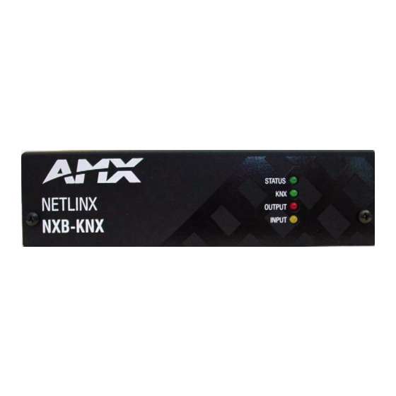
FIG. 1
NXB-KNX Interface
Product Specifications
NXB-KNX Specifications
Front Panel
• Status LED (green): Blinks once a second to indicate that
Components:
the unit has powered up.
Any state other than blinking once a second indicates the
unit is either not powered, or has not completed boot up.
• KNX LED (green): Solid on indicates power is on and the
unit is connected to KNX bus.
• Output LED (red): Lights to indicate traffic from the
NXB-KNX to the KNX bus.
• Input LED (yellow): Lights to indicate traffic from the KNX
bus to the NXB-KNX.
Rear Panel
• KNX 2-pin captive-wire connector:
Connectors:
• Ethernet Port - 10/100 Ethernet with PoE. LEDs show
communication activity, connection status, speeds, and
mode information:
SPD (speed) - Yellow LED lights On when the connection
speed is 100 Mbps and turns Off when the speed is
10 Mbps.
L/A (link/activity) - Green LED lights On when the Ethernet
cables are connected and terminated correctly, and blinks
when receiving Ethernet data packets.
Power Requirements: • PoE powered – no local Power Supply needed
• IEEE 802.3af Compliant
Memory:
• 64 Mbytes of RAM
• 256 Mbytes of FLASH
Dimensions (HWD):
With feet:
• 1.66" x 5.54" x 4.10"
• 4.216 cm x 14.07 cm x 10.42 cm
Without feet:
• 1.52" x 5.54" x 4.10"
• 3.861 cm x 14.07 cm x 10.42 cm
Weight:
1.45 lbs. (0.65 kg)
Operating
• Operating Temperature: 32°F - 104°F (0°C - 40°C)
Environment:
• Relative Humidity: 5% to 85% non-condensing
• Intended for indoor use only
Included Accessories: Black 2-Pin 5mm Phoenix connector with captive screws
Other AMX
• AC-DIN-CS3 DIN Rail Mounting Bracket (FG532-01)
Equipment:
• PS-POE-AF PoE Injector (FG423-80)
Certifications:
• FCC Class B
• CE
• IEC60950
• RoHS
NXB-KNX
Wiring and Connections
Note: To avoid any damage to the electronic component, installation must be
performed in an ESD safe environment.
Note: Do not connect power to the NXB-KNX until the wiring is complete.
The NXB-KNX is installed between the NetLinx Master and the KNX control bus,
and passes NetLinx control commands to the KNX control bus via 2-wire twisted
pair cabling, as indicated in FIG. 2:
NetLinx Master
(front)
PoE injector
Ethernet 10/100
FIG. 2
NXB-KNX installation
After completing the installation, consult the Using the Configuration Manager
(rear)
section of the NXB-KNX NetLinx Interface Operation/Reference Guide for
instructions on specifying IP and Security settings, via the NXB-KNX
WebConsole.
Ethernet 10/100 Base-T RJ-45 Wiring Configuration
The table below describes the pinouts, signals, and pairing for the Ethernet
10/100 Base-T connector and cable.
Ethernet Pinouts and Signals
Pin
Signals
1
TX +
2
TX -
3
RX +
4
no connection
5
no connection
6
RX -
7
no connection
8
no connection
FIG. 3 diagrams the RJ-45 pinouts and signals for the Ethernet RJ-45 connector
and cable.
FIG. 3
Straight-Through Wiring
PoE (Power Over Ethernet)
The NXB-KNX uses CAT5/CAT6 wire via the Ethernet port for PoE power.
Use the PS-POE-AF Power over Ethernet Injector (FG423-80) to simplify wiring
and installation by eliminating the need for an AC outlet at each point of
installation.
Note: The NXB-KNX can be placed up to approximately 330' (100 meters) from
the nearest PoE Injector.
•
If used with a non PoE-capable Ethernet switch (such as the
NXA-ENET24), then an optional PS-POE-AF Power-over-Ethernet (PoE)
power supply is required to provide power to the NXB-KNX.
•
If the NXB-KNX is used with a PoE-capable Ethernet switch (such as the
NXA-ENET24PoE), then no PoE Injectors are required.
Installation Guide
NetLinx NXB-KNX Interface
Control
NXB-KNX
2-wire twisted pair
Connections
Pairing
1 --------- 1
1 --------- 2
2 --------- 2
3 --------- 3
3 --------- 6
4 --------- 4
5 --------- 5
6 --------- 6
7 --------- 7
8 --------- 8
KNX
Bus
Color
White-Orange
Orange
White-Green
Blue
White-Blue
Green
White-Brown
Brown
Advertisement

Related Manuals for AMX NXB-KNX


Summary of Contents for AMX NXB-KNX
- Page 1 Note: To avoid any damage to the electronic component, installation must be performed in an ESD safe environment. Note: Do not connect power to the NXB-KNX until the wiring is complete. The NXB-KNX is installed between the NetLinx Master and the KNX control bus, and passes NetLinx control commands to the KNX control bus via 2-wire twisted pair cabling, as indicated in FIG.
- Page 2 ©2008 AMX. All rights reserved. AMX and the AMX logo are registered trademarks of AMX. AMX reserves the right to alter specifications without notice at any time. 3000 RESEARCH DRIVE, RICHARDSON, TX 75082 • 800.222.0193 • fax 469.624.7153 • technical support 800.932.6993 • www.amx.com Security Settings Select Security Settings from the Admin drop-down menu to open the Security Settings page.