
Related Manuals for Hawle HAWIDO 1403


Summary of Contents for Hawle HAWIDO 1403
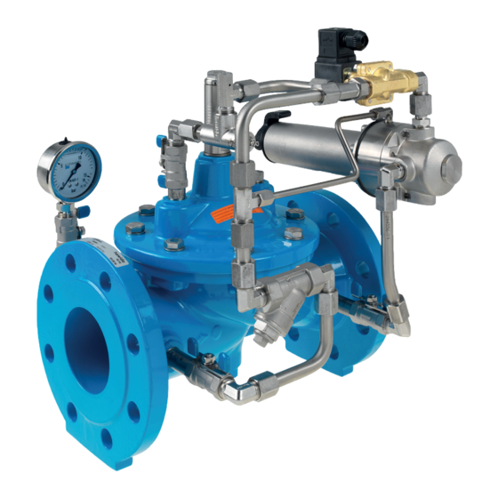
- Page 1 manual Pressure relief and pressure retention valve DAV for electrical control - open without current®...
- Page 2 HAWIDO - REGULATING VALVES Instruction for Pressure relief and pressure retention valve for electric control Type 1403/04 ND 40 to DN200 Keep this instruction manual at the location of the valve!
- Page 3 Example of rating plate After the commissioning, enter the following data and make use of this additional information regarding the valve type, pressure and flow ratios when consulting the manufacturer or the supplier or asking them questions: ……………… ………………….. Serial number: ...........
-
Page 4: Table Of Contents
DN 3/8" PN 10/16/25 ( STAINLESS STEEL CONTROL VALVE PARTS LIST 3.5 C ONTROL LINE INDIVIDUAL PARTS AND ACCESSORIES 3.6 2/2- WAY SOLENOID VALVE 3.7 O PTICAL POSITION INDICATOR RAWING 3.8 O PTICAL POSITION INDICATOR ARTS LIST ANNEX 1. T ORQUES HAWLE IN EUROPE... -
Page 5: Description
Damage to property and injuries to persons could occur as a result of improper installation, commissioning, operation and maintenance. The Hawle regulating valve (HAWIDO) has been designed for use in drinking and process water supplies. Other application media only after consultation with the manufacturer. -
Page 6: Recommended Installation
Recommended installation Before the installation of the fitting, the pipe lines must be carefully blown or flushed through to prevent any foreign material, such as pieces of wood, stones etc., from entering the regulating valve. The HAWIDO must be installed horizontally with the valve cover upwards (other models available on request). -
Page 7: Commissioning
B. Commissioning Functional diagram (1403) Components Main valve Ball valve (A, B, C) Filter Orifice plate One-way flow restrictor Control valve Pressure gauge Optical position indicator Electrical position indicator (optional) Valve opening limiter (optional) Solenoid valve Functional diagram (1404) Components Main valve Ball valve (A, B, C) Filter... -
Page 8: Preparatory Work
Preparatory work Before commissioning the valve, check that the gate valves on the inlet and outlet sides of the valve (or the slider on the inlet side) are/is closed and that the flange connections have been correctly tightened and sealed. On the valve: •... -
Page 9: Setting The Reaction Speed
• Gradually turn the adjusting lever of the control valve (6) (½ turn) according to the table below. • 1403. Remove power from solenoid valve (9) (➔ solenoid valve closes), the base valve close and remains closed. • Valve 1404: Apply power to the solenoid valve (9) (➔ solenoid valve closes), the base valve close and remains closed. -
Page 10: Fault Finding
Loud noise Unfavourable operating Change pressure by approx. 0.1 conditions to 0.2 bar. Slightly open or close the one-way flow restrictor. Contact the Hawle Customer Service department. Wrong valve size Have the correct valve size calculated (contact Hawle) Erratic operation... -
Page 11: Putting Out Of Service And Maintenance
D. Putting out of service and maintenance Putting out of service The operating valve must first be shut off hydraulically by proceeding as follows: • Slowly close the gate valves before and after the valve • Slowly close the ball valves (2A, 2B, 2C). In order to be able to carry out maintenance work on the valve, the solenoid valve must be disconnected from the power. -
Page 12: To 5-Year Maintenance
• Clean the filter with a brush or cloth, or replace it • Re-install the filter and screw the filter lid back on Checking the valve • Remove the vent plug from the valve cover. • Check that the valve spindle moves easily by raising and lowering it with the threaded rod. Putting back into service •... -
Page 13: Repair Kits And Spare Parts
-10- • Reassemble the control valve (see table in the annex for torques). Functional check of the one-way flow restrictor • Undo the locknut • Screw in the throttle screw, and then unscrew it as far as it goes • Screw in again a few turns. -
Page 14: Base Valve Dn 40 To Dn 200 (Drawing)
-11- 3.1 Base valve DN 40 to DN 200 (drawing) 08.12.2011/plü... -
Page 15: Main Valve (Parts List)
-12- 3.2 Main valve (Parts list) Item. Description Material Article number DN 40 DN 50 DN 65 DN 80 DN 100 Body GGG 40 1004 040 000 1004 050 000 1004 065 000 1004 080 000 1004 100 000 Valve cover GGG 40 1014 050 000 1014 050 000... - Page 16 -13- Article number Item Description Material DN 125 DN 150 DN 200° DN 200^ Body GGG 40 1004 125 000 1004 151 000 1004 200 000 1004 200 016 Valve cover GGG 40 1014 125 000 1014 151 000 1014 200 000 1014 200 000 Spindle guide cover INOX...
-
Page 17: Dav Stainless Steel Control Valve Dn 3/8" Pn 10/16/25 (Drawing)
-14- 3.3 DAV stainless steel control valve DN 3/8" PN 10/16/25 (drawing) 01.09.2017/plü... -
Page 18: Dav Stainless Steel Control Valve Dn 3/8" Pn 10/16/25 (Parts List)
-15- 3.4 DAV stainless steel control valve DN 3/8" PN 10/16/25 (parts list) Item Description Material Article number Control casing Stainless steel 1100 200 000 Cover Stainless steel 1108 200 000 O-ring NBR70 0180 020 025 Diaphragm DN3/8 EPDM (W270) 1121 000 000 Seat Compact Form 1.0, blank Stainless steel... -
Page 19: Control Line Individual Parts And Accessories
-16- 3.5 Control line individual parts and accessories Master number Picture Size Art. number Designation further sizes possibly available stainless steel/NBR 3/8“ 0130 012 000 0130 stainless steel/NBR 1/2" 0130 016 000 Compound seal stainless steel/NBR 3/4" 0130 025 000 Stahl/NBR 1“... - Page 20 -17- 3/8" stainless steel 0401 012 000 0401 1/2" stainless steel 0401 016 000 Sleeve 3/4" stainless steel 0401 025 000 1" stainless steel 0401 032 000 DN 6 - 1/8" stainless steel 0411 006 004 0411 DN12 - 3/8" stainless steel 0411 012 012 Adjuster nipple 0431...
- Page 21 -18- Stainless steel Y-filter IG 3/8" 0545 112 002 0545 Individual parts: Stainless steel dirt filter Stainless steel dirt filter 0545 900 051 Plug, complete for Y-filter, stainless 0545 112 010 steel 0545 112 011 Large seal for Y-filter, POM 0545 112 012 Small O-ring for plug 0545 116 000...
- Page 22 -19- AC coils with 0620 xxx xxx 0620, 0621 voltage indication Coils DC coils with 0621 xxx xxx voltage indication 0630 Appliance socket 0630 000 000 for electromagnet Appliance socket 0653 Connector modules for solenoid valves 0653 024 008 Type LBV 24 DC 8S, incl. 2m cable Connector modules Connector modules for solenoid valves 0653 230 000...
- Page 23 -20- From serial number14252 (January 1188 2003) 1188 065 100 Rep. Set DN40 to 100 1188 125 300 Control line DN125 to 300 From approx. serial number25915 (June 2014, 1188 000 000 Filter type B (0545 112 002) 1188 000 001 DN40 to 100 DN125 to 200 Polyamide tube OD 6 mm, ID 4 mm...
-
Page 24: 2/2-Way Solenoid Valve
-21- 3.6 2/2-way solenoid valve. normally closed ➔ Art. no.: 0610 510 001 3.6.1 Is installed in the following valve types: 1503, 1593, 1403, 1493, 1303, 1703, 1603 from DN125, 1706 from DN125/PN25 This version is fitted with a manual override Normal operation (C = closed): The letter C on the set screw is at the top. -
Page 25: Optical Position Indicator (Drawing)
-22- 3.7 Optical position indicator (Drawing) DN 40 – DN 100 DN 125 – DN 300 12.03.2014/plü... -
Page 26: Optical Position Indicator (Parts List)
-23- 3.8 Optical position indicator (Parts list) Item Description Material Article number DN 40 DN 50 DN 65 DN 80 DN 100 Indicator pin Stainless 1992 000 050 1992 000 050 1992 000 080 1992 000 080 1992 000 100 steel Compound seal ½’’... -
Page 27: Annex
-24- E. Annex Torques When assembling the base valve and the control valves all bolts are checked with a torque spanner according to the following list. Lightly grease the bolts before assembling! Nominal size Hex bolt Strength Tightening torque class Target Max. -
Page 28: Hawle In Europe
Dobogókoi út 5 telephone +36 (0) 26 501 501 H-2000 Szentendre fax +36 (0) 26 501 502 www.hawle.hu Hawle Armatury spol. s r.o. Ricanská 375 telephone +420 (0)2 410 03 111 CZ-25242 Jesenice u.Prahy fax +420 (0)2 41 00 33 33 www.hawle.cz...
Need help?
Do you have a question about the HAWIDO 1403 and is the answer not in the manual?
Questions and answers