Table of Contents
Advertisement
Quick Links
Advertisement
Table of Contents

Related Manuals for Hawle HAWIDO 1406


Summary of Contents for Hawle HAWIDO 1406
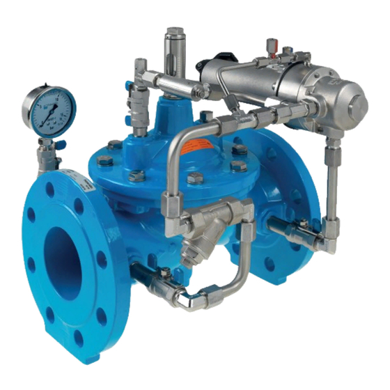
- Page 1 manual Pressure retention valve DAV with float control®...
- Page 2 HAWIDO - REGULATING VALVES Instruction for Pressure sustaining valve with float control Type 1406 ND40 to ND200 Keep this instruction manual at the location of the valve...
- Page 3 Example of a nameplate Once the commissioning work has been completed, enter the following data and always specify this additional information concerning the valve type, pressure and flow ratios, whenever you consult or have reason to question the manufacture or supplier: ………………...
-
Page 4: Table Of Contents
PRESSURE SUSTAINING STAINLESS STEEL DRAWING 3.4 C ONTROL VALVE PRESSURE SUSTAINING STAINLESS STEEL PARTS LIST 3.5 C ONTROL LINE AND ACCESSORIES 3.6 P OSITION INDICATOR DRAWING 3.7 P OSITION INDICATOR ARTS LIST ANNEX 1. T ORQUE TABLE HAWLE IN EUROPE... -
Page 5: Description
2 to 40º C General safety guidelines The Hawle HAWIDO regulating valve is designed for use in drinking water supply systems. Please consult the manufacturer before using it with other media. Material damage or injury to persons can occur if the HAWIDO is not installed, commissioned, operated or maintained according to these instructions or to codes of practice. -
Page 6: Recommended Installation
Recommended installation Before the installation, all pipe work must be blown or flushed through to prevent any foreign material such as pieces of wood, stone etc. from entering the valve. Regulating valves are normally fitted with the valve cover upwards. It is recommended that shut-off valves be fitted on both sides plus a dirt trap on the inlet side. -
Page 7: Recommended Installation Of Valves With Floater
Recommended Installation of Valves with Floater Recommended installation Prior to the installation of the valve, all the pipework must be purged carefully, to prevent the entry of any foreign bodies, such as pieces of wood, stones etc., in the control valve. Inlet pressures from 1.5 to 4 bar the Hawido floating valve type 1600 can be used together with a opening limiter. -
Page 8: Installation Control Valve With Float
For an inlet pressure of more than 4 bar, we recommend the employment of a combined control system with pressure reduction and/or orifice to reduce possible cavitation damage and high pressure surges. With inlet pressures of less than 1.5 bar, we advise you to contact us. To ensure trouble-free operation, we recommend the installation of a protective pipe for the float (available in PE or INOX). - Page 9 Pinhole pattern of the plate: Slot width: 9mm for M8 screws (use only corrosion-resistant screws) Setting the minimum and maximum water level • The water level Maximum (HAWIDO valve closed) and the water level Minimum (HAWIDO valve open) can be preset with the setting rings. These rings may have to be adjusted during the operating mode.
-
Page 10: Commissioning
B. Commissioning Functional diagram (1406) Components: max. min. Main valve 1200 Ball valve (A, B, C) Filter Orifice One-way flow restrictor Control valve Pressure gauge Position indicator Electrical position indicator (optional) Valve opening limiter (optional) Pilot valve Preparation Before commissioning the valve, check that the gate valves on the inlet and outlet sides of the valve are closed and that the flange connections are correctly tightened and sealed. -
Page 11: Adjustments Sustainable Pressure
Check: When the outlet gate valve is opened slightly the valve should close and remain shut. Then close the gate valve again. If the valve does not close, the commissioning procedure must be repeated from the preceding chapter onwards. Special care must be taken here to ensure that the upper valve chamber and control lines are properly vented. -
Page 12: Fault Finding
Resetting the reaction speed) Original pressure values no Pressure gauge faulty Check or replace pressure longer reached gauge Changed operating conditions Reset accordingly (see Chapter: Recommended installation) Epoxy-coating damaged Transportation damage, Repair using Hawle two- installation damage component repair kit for coatings... -
Page 13: Putting Out Of Service And Maintenance
-10- D. Putting out of service and Maintenance Putting out of service The operating valve must first be hydraulically shut off as follows: Slowly close the gate valves after and before the valve Slowly close the ball valves (2A, 2B, 2C) The valve is taken out of operation and the maintenance can be accomplished. -
Page 14: Four Or Five Annual Maintenance
-11- Checking the valve • Remove the position indicator from valve cover. • Check that the valve spindle moves easily by raising and lowering it with the threaded rod. • Install the optical position indicator. Putting the valve back into service •... -
Page 15: Repair Kits And Spare Parts
-12- Checking the operation of the one-way flow restrictor • Undo the locknut • Screw in the set screw and then unscrew it as far as it goes • Screw in again a few turns. This process must be easy and with little resistance Putting the valve back into service •... -
Page 16: Main Valve With Stainless Steel Connection Nd 40 To Nd 200 (Drawing)
-13- 3.1 Main valve with stainless steel connection ND 40 to ND 200 (drawing) 08.12.2011/plü... -
Page 17: Main Valve (Parts List)
-14- 3.2 Main valve (Parts list) Item. Description Material Article number DN 40 DN 50 DN 65 DN 80 DN 100 Body GGG 40 1004 040 000 1004 050 000 1004 065 000 1004 080 000 1004 100 000 Valve cover GGG 40 1014 050 000 1014 050 000... - Page 18 -15- Article number Item Description Material DN 125 DN 150 DN 200° DN 200^ Body GGG 40 1004 125 000 1004 151 000 1004 200 000 1004 200 016 Valve cover GGG 40 1014 125 000 1014 151 000 1014 200 000 1014 200 000 Spindle guide cover INOX...
-
Page 19: Control Valve, Pressure Sustaining, Stainless Steel (Drawing)
-16- 3.3 Control valve, pressure sustaining, stainless steel (drawing) -
Page 20: Control Valve, Pressure Sustaining, Stainless Steel (Parts List)
-17- 3.4 Control valve, pressure sustaining, stainless steel (parts list) Item Description Material Part number PN 16/25 Control housing to Compact pilot Stainless steel 1100 200 000 Bell to Compact with 1/8“ connection Stainless steel 1108 200 001 O-Ring NBR70 0180 020 025 Diaphragm DN3/8”... -
Page 21: Control Line And Accessories
-18- 3.5 Control line and accessories Masternumber Picture Size Art. number Description more sizes might be available 0130 stainless steel /NBR 3/8" 0130 012 000 stainless steel /NBR 1/2" 0130 016 000 Composite sealing stainless steel /NBR 3/4" 0130 025 000 ring steel/NBR 1“... - Page 22 -19- 3/8" stainless steel 0401 012 000 0401 1/2" stainless steel 0401 016 000 Sleeve 3/4" stainless steel 0401 025 000 1" stainless steel 0401 032 000 0411 DN 6 - 1/8" stainless steel 0411 006 004 DN12 - 3/8" stainless steel 0411 012 012 Adjustable male adaptor...
- Page 23 -20- Y-filter stainless steel IG 3/8" 0545 112 002 0545 Single components: Y-filter Filter sieve stainless steel 0545 900 051 Plug complete 0545 112 010 Seal big for Y-filter 0545 112 011 O-Ring 0545 112 012 Y-filter stainless steel 1/2“ 0545 116 000 Throttle valve DN 3/8"...
- Page 24 -21- Coil AC voltage 0620 Indicate the voltage 0620 xxx xxx Coil Coil DC voltage Indicate the voltage 0621 xxx xxx Appliance socket 0630 for electric coil 0630 000 000 Appliance socket for electric coil Plug module for solenoid valves Type 0653 024 008 0652, 0653 LBV 24 DC = 8-14S incl.
-
Page 25: Position Indicator (Drawing)
-22- Tools and accessories 1199 000 000 1199 1199 000 010 Spindel stroke tester Key for assembling the seal holder 1199 000 020 1199 of the pilot valve Tool for seal holder Ratchet with attachment for the one 1199 000 030 1199 way flow restrictor Ratchet with... - Page 26 -23- 12.03.2014/plü...
-
Page 27: Position Indicator (Parts List)
-24- 3.7 Position indicator (Parts list) Item Description Material Article number DN 40 DN 50 DN 65 DN 80 DN 100 Stainl. steel 1992 000 050 1992 000 050 1992 000 080 1992 000 080 1992 000 100 Seal½’’ Stainl./NBR 0130 016 000 0130 016 000 0130 016 000... -
Page 28: Annex
-25- E. Annex Torque table When assembling the main valve and the pilot valve, all bolts are checked with a torque wrench according to the following list. Grease the bolts before mounting ! Strenght class Diameter Hexagon bolt Tightening torque Reference Max. -
Page 29: Hawle In Europe
Dobogókoi út 5 Telefon +36 (0) 26 501 501 H-2000 Szentendre Telefax +36 (0) 26 501 502 www.hawle.hu Hawle Armatury spol. s r.o. Ricanská 375 Telefon +420 (0)2 410 03 111 CZ-25242 Jesenice u.Prahy Telefax +420 (0)2 41 00 33 33 www.hawle.cz... - Page 30 -27-...
Need help?
Do you have a question about the HAWIDO 1406 and is the answer not in the manual?
Questions and answers