Table of Contents
Advertisement
Advertisement
Table of Contents
Troubleshooting

Subscribe to Our Youtube Channel
Related Manuals for TCL TCA-18HRA/DVO


Summary of Contents for TCL TCA-18HRA/DVO
- Page 1 Technical Manual for DC Inverter Air Conditioner 1/ 113...
-
Page 2: Table Of Contents
DC Inverter Air CATALOG Part 1 General Information ........................... 5 1 Model Names of Indoor/Outdoor Units ........................ 5 2 External Appearance ............................... 6 2.1 Indoor Units ..............................6 2.2 Outdoor Units ............................... 6 3 Nomenclature ................................7 Part 2 Indoor Units .............................. - Page 3 DC Inverter Air 1) Installation Space..........................45 2) FLOOR CONSOLE TYPE ........................46 3) UNDER CEILING TYPE........................48 4) Installing indoor unit........................49 5) DRAINAGE PIPE CONNECTION ......................50 Part 3 Outdoor Units............................. 51 1.Specification ................................. 51 2 Sound Levels ................................. 55 3 Correction Curve of Capacity performance ......................
- Page 4 DC Inverter Air 3‐‐‐ Electronic expansion valve interface ..................88 4--Exhaust temperature sensor interface。 ................88 5--Temperature sensor interface of outdoor temperature and condenser tube ....88 6--Outdoor DC fan output ......................88 7--Four way valve output interface ...................88 8--Power input ..........................88 4) Description of Address DIP .......................89 3.3 TCA‐48/60HRA/DV3 Electric Control Box (ECB) ..................
-
Page 5: Part 1 General Information
DC Inverter Air Part 1 General Information 1 Model Names of Indoor/Outdoor Units 1.1 R410A (capacity multiplied by 1000Btu/h) 1.2 Outdoor Units Model of outdoor unit and corresponding indoor unit Universal Outdoor unit Model Compressor type Compressor Brand Matched indoor units TCB- 18CHRA/DVI(Q4) TCA‐18CHRA/DVI TCA‐18HRA/DVO... -
Page 6: External Appearance
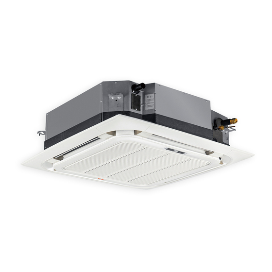
DC Inverter Air 2 External Appearance 2.1 Indo or Units Duct Ceiling & Floor 8‐way Cassette 2.2 Outdoor Units 6/ 113 6/ 113... -
Page 7: Nomenclature
DC Inverter Air 3 Nomenclature TC A – 24D2HE RA / DV3I I:INDOOR UNIT;O:OUTDOOR UNIT POWER SUPPLY: 3— 380V/50Hz/3Ph; ‐‐220~240V/50Hz/1Ph; DV—DC Inverter A—R410A R—remote control E—with auxiliary heater C‐Cooling only,H‐ Cooling and Heating D2—Middle static duct 24‐‐‐‐24×1,000 Btu/h Design style identity: A—first design style;B—second design style;... -
Page 8: Indoor Units
DC Inverter Air Part 2 Indoor Units 1 8‐way Cassette Type (Compact) 1.1 Specifications C A S S E T T E I N D O O R M o d e l T C B - C a s s e t t e In d o o r T C A - 1 8 C H R A / D V I T C A - 2 4 C H R A / D V I T C A - 3 6 C H R A / D V I n a m e 1 8 C H R A / D V I( Q 4 ) - Page 9 DC Inverter Air N e t I n d o o r w e i g h t G r o s s U n i t ( W x H x D ) 6 5 0 x 3 0 x 6 5 0 9 5 0 ×4 5 ×9 5 0 9 5 0 x 4 5 x 9 5 0 9 5 0 x 4 5 x 9 5 0...
- Page 10 DC Inverter Air B r a n d L ife n g L ife n g M o d e l Y D K 5 6 - 6 - 6 Y D K 5 6 - 6 - 6 In p u t 1 4 3 /1 1 7 /1 0 3 1 4 3 /1 1 7 /1 0 3 In d o o r fa n m o to r...
-
Page 11: Dimensions
DC Inverter Air 1.2 Dimensions 2 90 36/ 48/6 0k 1 46 1 34 4 -install hanger 6 63 1 23 Gas side Liguid side E- parts box Pum p i nspe ct hol e Drain hole 1 34 6 60 1 89 8 30 CONSTITUTION OF PANEL... -
Page 12: Service Space
DC Inverter Air 1.3 Service Space HEIGHT BETWEEN CEILI NG AND FLO OR The installat ion height b etween ceiling and floor must be 2.7m~3.2m. 12/ 113... -
Page 13: Electrical Wiring Diagram
DC Inverter Air 1.4 Electrical Wiring Diagram 13/ 113... -
Page 14: Air Velocity And Temperature Distributions
DC Inverter Air 1.5 Air Velocity and Temperature Distributions Airflow velocity 14/ 113... -
Page 15: Sound Levels
DC Inverter Air 1.6 Sound Levels Noise leve l dB(A) Model TCA‐1 8CHRA/DVI TCA‐2 4CHRA/DVI TCA‐3 6CHRA/DVI TCA‐4 8CHRA/DVI TCA‐6 0CHRA/DVI 1.7 Accessories (Options Name Shape Quantity INSTALLATION FITTINGS Installation paper board Soundproof / insulation s heath Tubing & Fittings Connecting pipe group Out‐let pipe sheath Out‐let pipe clasp... -
Page 16: The Specification Of Power
DC Inverter Air Remote controller holder Mounting screw(ST2.9×10‐C‐H) Alkaline dry batteries (AM4) Owner's manual Others Installation manual Installation accessory Expansible hook (The product you have might not be provided the following Installation hook accessories Orifice 1.8 The Specification of Power MODEL TCA‐18CHRA TCA‐24CHRA... -
Page 17: Installation Requirements Of Indoor Unit
DC Inverter Air 1.9 Installation Requirements of Indoor Unit 1) CEILING HOLE AND THE HOOK INSTALLATION Preparation Work on the Ceiling Installation methods should be changed under the different construction structure. Please consult the professional for the detailed information. After opening a hole, the ceiling should be horizontal and strong to prevent vibration. - Page 18 DC Inverter Air Overhanging the indoor unit Adjust the gasket (down side) to 90mm over the ceiling. Install the hanging bolt into T groove of the hanging tool. Overhang the indoor unit and ensure it is level using a level in dicator. 18/ 113...
-
Page 19: Drainage Pipe Installation
DC Inverter Air 2) DRAINA GE PIPE INSTALLATIO N CAUTION The drain pipe of indoor unit must have the heat insulation , or it will condense dew, as well as the connections of the indoor unit. The declivity of the drain pipe downwards should be over 2/100, and no winding and bending. The total length of the drain pipe when pulled out traversely should not exceed 20m , when the pipe is over long, a prop stand must be installed every 1.5 to 2m to prevent winding. - Page 20 DC Inverter Air Drainage Upward To make sure that the drainage pipe would not be slanteddownward, lead it upward to a height 360mmmaximum,then downward lead it. Drainage Test Check whet her the drain pipe is unhindered before testing. 1) Stow water from sprue to check. 2) Stow 600cc water with pot or hose from sprueslowly , preventing touchng the drain pump motor.
-
Page 21: Installation Of Panel
DC Inverter Air Motor Sound Test The drainage test is doing during checking the drain pump motor running sound . Reset the water level switch connection to the original position after the drainage test . 3) INSTALLATION OF PANEL 1 BODY DIMENSION: INSTALLATION OF PANEL 1.Please screw M10 gasket and M6 *20 bolt at the corner of indoor unit ,before scre wing them fasten ,screw other two a dditional bolts which locates red bolt s howing as figure and notice that the direction of red arrow... - Page 22 DC Inverter Air 22/ 113...
-
Page 23: Duct Type
DC Inverter Air 2 Duct Type 2.1Specifications Model TCA‐18D2HRA/DVI TCA‐24D2HRA/DV3I Type Control type Remote Controller Standard Static pressure Range 0~40 0~50 Capacity Btu/h(W) 18(5274) 24(7074) Cooling Input 1635 2180 capacity Current 3.22 3.22 Capacity Btu/h(W) 19800(5800) 26000(7620) Heating Input 1810 2350 capacity Current... - Page 24 DC Inverter Air Coil 761×252×38.1 761×252×50.8 length×height×width Number of circuits Fan System Indoor air circulation(Cooling/Heating) m3/h 1100/900/700 1300/1100/900 Indoor fan type Centrifugal Centrifugal Connections Connecting Liquid 6.35 9.52 Pipe 12.7 15.88 Max. height drop (high head) Max. length of connecting pipe Refrigerant charge with long pipe Drainage Pipe O.D32...
- Page 25 DC Inverter Air 3.63 3.50 3.37 Indoor noise High dB(A) level at Med. dB(A) cooling(sound pressure level) dB(A) Refrigerant Type R410A R410A R410A type/Quantity Design pressure 4.2/1.5 4.2/1.5 4.2/1.5 Electrical Data Power supply 220‐240V~/50Hz 220‐240V~/50Hz 220‐240V~/50Hz Voltage Range 220~240 220~240 220~240 Refrigerating System Model...
- Page 26 DC Inverter Air Net dimensions (W x H x D) 1140×270×710 1200×300×800 1200×300×800 Net weight Packing dimensions (W x H x D) 1345×360×830 1405x375x925 1405x375x925 Gross weight Loading Capacity Note Specifications are based on the following conditions: Cooling: Indoor temperature 27℃ DB/19℃WB,and outdoor temperature 35℃...
-
Page 27: Dimensions
DC Inverter Air 2.2 Dimensions Position size of descens ional ventilation 1. The positioning of celling hole, indoor unit and opening. hanging screw bolts . Size of mounted hook Air inlet size Siz e of Out line dimension Ai r outlet opening size Air return opening size mounted lug 713 35... -
Page 28: Service Space
DC Inverter Air 2.3 Service Space 2.4 Wiring Diagrams 28/ 113... -
Page 29: Sound Levels
DC Inverter Air 2.5 Sound Levels Concealed Duct Typ e Discharge Suction Duct Duct 1.4m M icrophone Noise level dB(A) Model TCA‐18D2HRA/DVI TCA‐24D2HRA/DVI TCA‐36D2HRA/DVI TCA‐48D2HR A/DV3I TCA‐60D2HR A/DV3I 2.6 Acce ssories (Options) Name Shape Quantity S oundproof / insulation sheath Tubing &... -
Page 30: The Specification Of Power
DC Inverter Air Mounting screw(ST2.9 10‐C‐H) Alkaline dry batteries (AM 4) Remote controller manual Wired control ler & Its Frame W ired controller , Owner s manual Others In stallation manual Magnetic ring (twist the electric wires L EMS & It’s fitting and N around it to five circles) 2.7 The Specification of Power MODEL... -
Page 31: Installation Requirements Of Indoor Unit
DC Inverter Air INDO OR/OUTDOO R CONNECTION 3*2.5 3*2.5 3*2.5 WIRING( STRANG ELECTRIC SIGNAL (MM 2.8 Installation Requirements of Indoor Unit Choice of air return ways This indoor unit is fitted with downward air return, which can be change to its backward counterpart if necessary. -
Page 32: Hanging &Installation Of Indoor Unit
DC Inverter Air Wooden construction Timber over the beam Put the square timber over the roof beam,t hen install the hanging screw bolt . Roof be am Ceilin g Hanging screw bolt New concrete bricks Inlaying or embedding the screw bolt (Blade shape insertion ) (Slide insertion) Finished concrete bricks... -
Page 33: How To Mount Outlet Pipe
DC Inverter Air Gradienter H anging Bolt Nuts (Up) Gas ket(Upside) Inst alling Ear Must Be Fixed Tight Gas ket(Dow nside) Nut(Downside) B elow thec eiling Hang the nut inside the U slot of the installation panel.To confirm level degree with gradienter . -
Page 34: Tips For Installation Of Return Air Pipe And Outlet Pipe
DC Inverter Air Riv et Return air pipe Unit Canvas air conduit Canvas air conduit Return air pipe Return air window Installation mode for sidewise air intake Installation mode for underside air intake 5) Tips for Installation of Return Air Pipe and Outlet Pipe To minimize energy loss occurring in transmission process and condensed water during heating operation, return air pipe and outlet pipe shall be equipped with heat‐insulating layer as shown in the figure.:... -
Page 35: Installation Of Drain Pipes
DC Inverter Air The configuration of air conduit joint on the site may not reduce its effective cross section; The support and hanger of air conduit cannot be set up at air port, valve, manhole and automatic control mechanism; the boom/suspender shall not be directly fixed on the flange; The configuration of air conduit joint on the site may not reduce its effective cross section;... - Page 36 DC Inverter Air Til t ≥ Heatinsulation Tra p Dra in sto ppe r (SitePreparation) Add-ondrainpan ≥ Hea t ins ula tio n (SitePreparation) (Si te pre par ati The structure of dra inp ipe beconvenien clean Unit: mm Drainage Experiment ◆Before the test, it is necessary to ensure the unblocking state of drain pipes, and check the sealing performance of various joints;...
-
Page 37: Ceiling& Floor Type
DC Inverter Air Ceiling& Floor Type 3.1 Specifications Model TCA‐18ZHRA/DV TCA‐24ZHRA/DV3 Capacity Btu/h(W) 18000(5274) 24000(7034 Cooling Input 1635 2180 capacity Current 3.32 3.22 Capacity Btu/h(W) 19800(5800) 26000(7620) Heating Input 1810 2350 capacity Current 10.6 3.43 3.34 Indoor noise High dB(A) level at Med. - Page 38 DC Inverter Air Coil 810×294×25.4 810×294×25.4 length×height×width Number of circuits Fan System Indoor air circulation(Cooling/Heating) m3/h 1000/950/850 1300/1200/1100 Indoor fan type Centrifugal Centrifugal Connections Connecting Liquid 6.35 9.52 Pipe 12.7 15.88 Max. height drop (high head) Max. length of connecting pipe Refrigerant charge with long pipe Drainage Pipe O.D32...
- Page 39 DC Inverter Air Model TCA‐36ZHRA/DVI TCA‐48ZHRA/DV3I TCA‐60ZHRA/DV3I Capacity Btu/h(W) 36000(10550) 48000(14000) 60000(17500) Cooling Input 3090 4140 5500 capacity Current 15.0 3.41 3.38 3.18 Capacity Btu/h(W) 40000(11700) 53000(15530) 63000(18400) Heating Input 3270 4438 5420 capacity Current 15.5 10.1 3.58 3.39 Indoor noise High dB(A) level at...
- Page 40 DC Inverter Air Indoor fan type Centrifugal Centrifugal Centrifugal Connections Connecting Liquid 9.52 9.52 9.52 φ19.05 φ19.05 φ19.05 Pipe Max. height drop (high head) Max. length of connecting pipe Refrigerant charge with long pipe Drainage Pipe O.D25 O.D25 O.D25 Others Net dimensions (W x H x D) 1275x675x235 1635x675x235...
-
Page 41: Wiring Diagrams
DC Inverter Air 3.2 Wirin g Diagra ms 41/ 113... -
Page 42: Air Velocity And Temperature Distributions
DC Inverter Air A irflow velo city Discharge angle 60°(FLOOR) 42/ 113... - Page 43 DC Inverter Air Airflow velocity Temperature 43/ 113...
-
Page 44: Sound Levels
DC Inverter Air 3.4Sound Levels Ceiling F loor Noise level dB(A) Model TCA‐18ZHRA/DVI TCA‐24ZHRA/DVI TCA‐36ZHRA/DVI TCA‐48ZHRA/DVI TCA‐60ZHRA/DVI 3.5 Accessories (Options Name Shape Quantity 1.Hook Installation fittings 2.Hanging arm 3. Remote controller Remote contro ller & Its 4. Remote controller holder holder 5. -
Page 45: The Specification Of Power
DC Inverter Air 7. Owner's manual Others 8. Installation manual 9. Remote controller manual 3.6 The S pecification of Pow er MOD EL TCA‐18ZHR A/DV TCA‐24ZHRA/D V3 INDOOR PHASE 1‐PHASE 1‐PHASE UNIT FREQ UENCY AND V OLT 220‐240V 0Hz 220‐240V 50Hz POWER POWER WIRING (M M 3*2.5... -
Page 46: Floor Console Type
DC Inverter Air Under ceilin g Installation procedure Please remove the grille and the side board. 2) FLOOR CONSOLE TYPE 1. Select the piping and drainage directions. The piping and drain can be made in two directions as shown below(fig.1). When the direction is selected,please drill a 100mm(4″)diameter hole on the wall,and the hole must be tilted downward towards the outdoor for smooth water flow.When the pipe is led out from the rear,make a hole in figure,at the position shown(fig.2). - Page 47 DC Inverter Air Insert the anchor bolts in to the drilled holes, and drive the pins completely into the anchor bolts with a hammer. 2.Drilling holes for anch or bolts and installing the anchor blots(m10) According to the position of the hole, install two expansible anchor bolts(A and B) at the position shown in the figure.
-
Page 48: Under Ceiling Type
DC Inverter Air Install the unit to them with nuts,washers and sp ring washer s NOTE: The installation angle should not exceed 15 degrees. CAUTION Be sure to arrange the drain hose so that it is leveled lower than the drain hose connecting port of the indoor unit. -
Page 49: Installing Indoor Unit
DC Inverter Air CAUTION: Install the drainage hose at the rear,it should not be installed on the top . When the directions are selected, drill 80 mm (3‐1 /8") and 50 mm (2") or 150 mm (6") d ia. hole on the wall so that the hole is tilted do wnward toward the outdo or for smoot h water flow. -
Page 50: Drainage Pipe Connection
DC Inverter Air 5) DRAINAGE PIPE CONNECTION 1.Installing the drain hose Insert the drain hose into the drain pan, then secure the drain hose with a ylon fastener(we have co nnected the drain hose to the drain pan in the factory,you just need connect the drain pipe.). Wrap the insulation (dra in hose) around the drain hose connection. -
Page 51: Part 3 Outdoor Units
DC Inverter Air Part 3 Outdoor Units 1.Specification Model TCA‐36HRA/DVO TCA‐48HRA/DV3O TCA‐60HRA/DV3O Control type Capacity Btu/h(W) 36000(10550) 48000(14000) 60000(17500) Cooling Input 3050 4180 5420 capacity Current 15.0 3.46 3.35 3.23 Capacity Btu/h(W) 40000(11700) 53000(15530) 63000(18400) Heating Input 3224 4440 5460 capacity Current 15.5... - Page 52 DC Inverter Air Fin spacing Fin type Hydrophilic aluminium Hydrophilic aluminium Hydrophilic aluminium Tube outside dia.and Φ7,inner grooved Φ7,inner grooved tube Φ7,inner grooved tube type tube Coil length * height * 927.8×822×36.4 910×1218×25.4 910×1218×38.1 width Number of circuits Fan System Outlet size of indoor airflow Outdoor fan type Propeller...
- Page 53 DC Inverter Air Model TCA‐18HRA/DV TCA‐24HRA/DV Control type Capacity Btu/h(W) 18000(5274) 24000(7034) Cooling Input 1635 2180 capacity Current 3.32 3.22 Capacity Btu/h(W) 19800(5800) 26000(7620) Heating Input 1810 2350 capacity Current 10.6 3.43 3.34 Outdoor noise level(sound power levle) dB(A) Type R410A R410A Refrigerant...
- Page 54 DC Inverter Air Coil length * height * 776×570.5×36.4 896×611×36.4 width Number of circuits Fan System Outlet size of indoor airflow Outdoor fan type Propeller Propeller Connections Connecting Liquid 6.35 9.52 Pipe 12.7 15.88 Max. height drop (high head) Max. length of connecting pipe Refrigerant charge with long pipe Drainage Pipe Others...
-
Page 55: Sound Levels
DC Inverter Air 2 Sound Levels Model Noise level dB(A) TCA‐1 8HRA/DVO TCA‐2 4HRA/DVO TCA‐3 6HRA/DVO TCA‐48HRA/DV3O TCA‐60HRA/DV3O 3 Correction Curve of Capacity performance . Correction of Cooling Capacity Valid Cooling Capacity = Rated Cooling Capacity × Correction Coefficient [(1)×(2)×(3) ×(4)] Notes: ( 1)×(2)×(3)×(4) refers to the correction coefficients for the following four figures. -
Page 56: Correction Of Heating Capacity
DC Inverter Air (2) Correction Coefficient of Outdoor Dry‐bulb Te mperature (3) Correction Coefficient of Piping Length Piping Length of Outdoor Unit (5m‐50m) Precautions: A. It is equally applicable whether or not the outdoor unit is above or below the indoor unit; B. - Page 57 DC Inverter Air Notes: ( 1)×(2)×(3)×(4 ) refers to the correction coefficient of the followin g four figures. (1) Correction Coefficient of Indoor Dry‐Bulb Temp erature (2) Correction Coefficient of Outdoor Wet‐Bulb Temperature (3) Correction Coefficient of Piping Length Pipin g Length of Outdoor Unit (5‐50m) Precautions: A.
-
Page 58: Normal Operation Temperature Range
DC Inverter Air 4. Normal Operation Temperature Range Cooling Heating 5. Installation Dimension Drawing of Outdoor Unit Split type outdoor unit Fig. 1 Fig.2 58/ 113... -
Page 59: Installation Requirements Of Outdoor Unit
DC Inverter Air M ODE R EMA RK 7 80 5 2 1 29 0 3 28 2 90 2 88 6 05 Fig .1 9 00 7 5 3 34 9 3 99 3 15 3 04 6 50 Fig .1 9 40 6 0 0... -
Page 60: Installation Requirements Of Side Air Outlet Outdoor Unit
DC Inverter Air where is easily subject to combustible gas leakage; where there are a lot of oil (including engine oil); where there is a higher salt content (coastal region); Where there is a lot of sulfide gas; ... - Page 61 DC Inverter Air 3) Minimum Distance between Upper Side and Lower Side More than 650MM 4) Minimum Distance for Relative Arrangement of Front Face in the Same Plane (Air Outlet Side): Wind direction Wind direction More than 650CM 5) Minimum Distance for Relative Arrangement of Back Face in the Same Plane (Air Return Side): More than 100CM Wind direction Wind direction...
-
Page 62: Electrical Design
DC Inverter Air 6) Front/Rear Arrangement of Outdoor Units in the Same Plane (Air outlet in same direction, namely, the air outlet of the rear outdoor unit faces towards the air inlet of the front unit): It is necessary to put an end to this installation mode! Because the return air of the front unit may seriously affect the exhaust air of the rear unit! Wind direction Wind direction... - Page 63 DC Inverter Air MODEL INDOOR PHASE 1‐PHASE 3‐PHASE 3‐PHASE UNIT FREQUENCY AND VOLT 220‐240V 50Hz 220‐240V 50Hz 220‐240V 50Hz POWER POWER WIRING (MM 3*2.5 3*2.5 3*2.5 CIRCUIT BREAKER (A) OUTDOOR PHASE 1‐PHASE 3‐ PHASE 3‐ PHASE UNIT FREQUENCY AND VOLT 220‐240V 50Hz 380V 50Hz 380V 50Hz...
-
Page 64: Electrical Wiring Diagram
DC Inverter Air 7.2. Electrical Wiring Diagram 2.1 TCA‐36HRA/DV 64/ 113... - Page 65 DC Inverter Air 2.2 TCA‐48H RA/DV3, TCA‐60HRA/DV3 65/ 113...
- Page 66 DC Inverter Air 2.2TCA‐18HRA/DVO, TC A‐24HRA/DVO 66/ 113...
-
Page 67: Design And Installation Of Connecting Pipes
DC Inverter Air 8. Design and Installation of Connecting Pipes 8.1. Pipe length and drop height shall comply with the scope required below. Mode Max pipe length Max drop height l Max bending No. The refrigerant shall be increased while the 22g/m 65g/m mounted pipe is more... -
Page 68: Precautions For Installation
DC Inverter Air 8.3. Precautions for Installation: 3.1 Installation Confirm the model, name and specification to avoid the faulty installation. 3.2 Refrigerant Piping A. The refrigerant piping must adopt the pipe diameter specified; B. The refrigerant piping must be subject to insulation treatment; C. - Page 69 DC Inverter Air Clamp and flatten the en d of copper tube and then weld it. B. B inding Method Wrap the copper tube with PVC tapes C. Special attention shall be p aid to the following operations: When p assing the c opper tube t hrough the hole (the dirt may easily en ter the pipe) When t he copper t ube gets into the outdo or area (th rain may easily enter the pipe, inp articular, special attention shall be pai d when the pipe is in a vertical state) 2) Preca utions for Material Protection of Refrigerant Pipe...
- Page 70 DC Inverter Air B. The opening of the pipe must be block ed and capped while it passes through the wall. C. The pipe shall not be placed on the ground or rubbed against the ground. D. T he pipe opening shall be upside down while removing the burr after cutting the pipe. E.
- Page 71 DC Inverter Air 2) Th e attention shall be paid to the assembly direction and angle of the liquid pipe and gas pipe openings to avoid the oil backflow or accumulation; 3) The alternative method for nitrogen injection is the standard operation method during the welding operation.
- Page 72 DC Inverter Air shall be paid to that the saw dust cannot enter the pipeline); 3) The flaring tool shall be used and the size of flare opening shall remain as follows: Do not forget to consider the pipe nut in the situation specified for processing of flare opening. Shape and Size of Flare Opening: Dimension table (unit: mm) Outer diameter D...
- Page 73 DC Inverter Air 5. Laying of Refrigerant Pipes 1) Laying of Refrigerant Pipes The system shall be clear and a system sign shall be marked at some distance to avoid the improper connection. 2) Protection of Outdoor Refrigerant Pipes In addition to the insulation layer, some outdoor refrigerant pipes shall be subject to the treatment against the expected damage.
-
Page 74: Heat Insulation Works
DC Inverter Air Recharging Amount: R (Kg) = (L1‐L2)×A/m) Where, L1— actual length of liquid pipe (m); L2— actual standard length for delivery (m) (see the Recharging label of the outdoor unit) A—The refrigerant to be added for pipe m, see the following table. Pipe specification φ6.4 φ9.5... - Page 75 DC Inverter Air B. The welding area, flared area or flan ge area shall be subject to the heat‐insulation treatment after completing the leakage d etection. 2) He at Insulation of Non‐weld ed or Non‐c onnected Po sitions In order to facilitate the construction, please use t he heat insulation materials to deal with the pipes b efore their laying, and meanwhile, a certain length at two ends of the pipe shall be res erved not for the insulation treatment for purpose o f welding an d leakage de tection after completing the laying of the pipe.
-
Page 76: Heat Insulation Of Drain Pipes
DC Inverter Air The wrapping tapes shall be used for the wrapping treatment after completing the insulation treatment and no sense of relaxation shall prevail. 9.3. Heat Insulation of Drain Pipes The heat insulation treatment of drain pipes shall be extended to the juncture (position), or it may cause the condensation at the position without heat insulation treatment. -
Page 77: Part 4 Maintenance
DC Inverter Air Part 4 Maintenance 1. Troubleshooti ng of Inv erter Sys tem 1.1. 8‐wa y cassette; 4‐way c assette 8‐way cassette 4‐way cassette 1.2. Ceiling & Floor Runn in g light Timing light Ma nual Switch TIM ER Nixi e tube DEFRO S FAU LT... -
Page 78: Duct
DC Inverter Air Display function declaration LED light the state of running light When powered‐on the first time, the running light twinkles, while the double‐8 does not lit. When started‐up normally, the running light lights on, while the double‐8 shows the designed temperature. When operated normally, the running light lights on, while the double‐8 shows the designed temperature. -
Page 79: Fault Identification: Determine The Fault Type According To The Symptom
DC Inverter Air When powered‐on the first time, the running light twinkles, while the double‐8 does not lit. When started‐up normally, the running light lights on, while the double‐8 shows the designed temperature. When operated normally, the running light lights on, while the double‐8 shows the designed temperature. When closed down, both LED and double‐8 are gone out. - Page 80 DC Inverter Air (1) The design load for the air‐conditioner is not enough; (2) Improper installation results in no wind from the air conditioner; (3) The return air design of air conditioner is unreasonable, resulting in an unreasonable air flow in the room and uneven room temperature;...
-
Page 81: Control System
DC Inverter Air running; (1) Common Protection of AC System General Protection: it is the protection function designed to protect the air conditioner (AC) from being damaged by the possible big current, high temperature and high voltage (delay protection three minutes after the start of compressor, phase sequence, phase‐loss protection, low/high voltage protection, over‐voltage and under‐voltage protection of inverter compressor, exhaust air temperature protection, module protection, etc.);... - Page 82 DC Inverter Air 82/ 113...
- Page 83 DC Inverter Air In such a system, the control pa nel of indoor unit receive s from the user the signals (e.g. set temperature, fan spe ed, etc.) sent through co ntrol ways of remote con troller, line controller, central controller, intelligent network AC management system (PC control), etc., and environment information (e.g.
-
Page 84: Electrical Control Of Outdoor Unit And Troubleshooting
DC Inverter Air 3.2. Electrical Control of Outdoor Unit and Troubleshooting Main Control Board of Outdoor Unit(36K 48K 60K ) 1 2 3 4 9 10 Description of Main Control Board of Outdoor Unit 1 — Low‐wind output of AC motor of outdoor unit,220‐240V 2 —... -
Page 85: Spot-Inspection Description Of Outdoor Unit
DC Inverter Air 16— TE(T3 OR OPT), condenser defrosting temperature sensor input 17— TP, compressor exhaust temperature sensor input 18— TS(T5), compressor return air temperature sensor input 19— Reserved interface for temperature sensor 20— PID of piping length 21— Spot‐inspection button 22—... -
Page 86: Display Of Fault Codes
DC Inverter Air Machine running fault 1 Display code, 0 for No Fault Machine running fault 2 Display code, 0 for No Fault Machine running fault 3 Display code, 0 for No Fault Machine running fault 4 Display code, 0 for No Fault Machine running fault 5 Display code, 0 for No Fault Spot‐Inspection End... - Page 87 DC Inverter Air Low pressure switch fault (open circuit Stop system, shoot trouble, need to for frequency 0) re‐energize it to resume operation Stop system, release protection, resume Over/under‐voltage protection operation Stop system, release protection, resume Inverter module protection operation High voltage switch protection Stop system, release protection, resume operation...
-
Page 88: 24K Outdoor Pcb
DC Inverter Air 18K ,24K outdoor PCB 1‐‐‐ Compressor drive output,UVW 2‐‐‐ Monitor and test ou tput 3‐‐‐ Electronic expansion valve interface 4--Exhaust temperature sensor interface。 5--Temperature sensor interface of outdoor temperature and condense tube 6--Outdoor DC fan output 7--Four way valve out put interface 8--Power input 88/ 113... -
Page 89: Description Of Address Dip
DC Inverter Air 4) Description of Address DIP a.Capacity of Outdoor Unit (Model DIP) (14) SW410 Model(HP)(BTU)(*100W) SW410(8‐1) TCA‐36HRA/DV 0100 0000 TCA‐48HRA/DV3 0011 0000 TCA‐60HRA/DV3 0000 0000 Note: 1 –ON; 0 ‐ OFF b.Piping Length DIP of Outdoor Unit (20) SW411: SW411(4——1 )... - Page 90 DC Inverter Air Communication terminal block of indoor/outdoor units 4— Outdoor power supply filter board; 5— Fan capacitor; 6— Electrolytic capacitor 7— Reactor Compressor Driver of Outdoor Unit, Fault and Protection 1— Communication between compressor driver and main control panel 2—...
-
Page 91: Tca-36Hra/Dv Electric Control Box (Ecb)
DC Inverter Air 3.4 TCA‐36HRA/DV Electric Control Box (ECB) ECB Structure of Outdoor Unit 1— Power supply terminal block of outdoor unit Indoor/outdoor communication terminal block 2— Main control panel of outdoor unit 3— Outdoor power filter board 4— Compressor driver module of outdoor unit Compressor Driver, Fault and Protection 1‐... -
Page 92: Troubleshooting And Repair
DC Inverter Air Normally ON: Driver running 6‐ LED Indicator Light LED704(red) Normally ON: Driver is ON OFF: Driver is OFF List of Shutdown Protection Faults Fault Code Fault Content IPM over current Compressor drive failure protection Compressor over‐current (Peak Value) Reserve Compressor phase current sampling fault IGBT shell over‐heat shutdown... - Page 93 DC Inverter Air (2) Troubleshooting and Protection based on Fault Codes H**: refers to the number of indoor units connected with the outdoor unit, which is displayed when all indoor units are in standby state. It displays “Dxx” when the outdoor unit is in the defrosting state; It displays “Cxx”...
- Page 94 DC Inverter Air replace the main control panel (MCP). E05: open/short‐circuit fault of outdoor ambient temperature sensor (TABM,T1) Treatment Method: Sensor Fault Check sensor Use the resistor gear of multi‐meter to measure the resistance of sensor to check whether it corresponds to that of temperature sensor in attached Replace sensor Use the resistor gear of multi‐meter to measure the pull down...
- Page 95 DC Inverter Air 3. If the voltage is not normal, please replace the motherboard of outdoor unit. E23: EEPROM fault of outdoor unit Treatment Method: 1. Change EEPROM of outdoor unit (upgrade the EEPROM data); 2. Replace the motherboard of outdoor unit; E30: DIP Fault of model selection of indoor/outdoor unit Treatment Method: 1.
- Page 96 DC Inverter Air P03: Inside Function Protection of Inverter Module (see Compressor Driver Fault and Protection Codes for details) Treatment Method: 1. Whether the module communication line is reliably connected with the communication interface of main control panel; 2. Whether the module DC power supply is 310V or so for single phase (530V for three phases); 3.
- Page 97 DC Inverter Air Testpower Check whether the power supply supplycurrent complies with the applicable scope of equipment in nameplate Test current Check system pressure, transducers Use method of exclusion compressor load, etc. without load Transducer current shall be less than the value in nameplate Replace damaged load Replace main control panel P21: Low Pressure Protection of the System...
- Page 98 DC Inverter Air 2. If it is normal, please test whether the resistance of exhaust temperature sensor is consistent with that in attached page (Annex 3); 3. If it is normal, please replace the main control panel. P34: Driver Radiator Temperature Protection of Outdoor Unit Treatment Method: 1.
- Page 99 DC Inverter Air Evaporator tube The temperature of the indoor tube is higher than the set value temperature sensor when cooling mode. Condenser tube The temperature of the indoor tube is higher than the set value temperature sensor when heating mode. System fault The tube temperature is abnormal in cooling or heating indoor fan fault...
- Page 100 DC Inverter Air If three compressor exhaust high temperature protections occur within one hour, the protection will be changed into the fault code (E8) and then the system will automatically shut down and be locked, and it is required to switch off and re‐energize to resume the operation. P3: High Pressure Protection of the System Treatment Method: 1.
-
Page 101: Electrical Control And Troubleshooting Of Indoor Unit
DC Inverter Air 3.6 Electrical Control and Troubleshooting of Indoor Unit 1). Description of Motherboard of Indoor Unit (cassette) 12 11 10 1— Transformer Input socket, 220v high voltage 220V‐240V is inputted to transformer 220V power supply of the power board is inputted to the socket and transmitted here via fuse and PTC protector. -
Page 102: Description Of Motherboard Of Indoor Unit (Duct/ Ceiling & Floor)
DC Inverter Air 10—wire controller 11—SW2 12—SW1 Indoor Unit Type DIP 13—Transformer Output AC power supply is inputted into transformer, and the transformer will output 15V and then input to the electric control panel. 14—POWER SOUREC input interface 15—FUSE 2) Description of Motherboard of Indoor Unit (Duct/ Ceiling & floor) 2 3 4 11 10 1—Transformer Input socket, 220v high voltage... - Page 103 DC Inverter Air 4— Ind oor Fan Output 220V‐240V output, four relays and four wind gears on electric control panel: high wind, middle wind, low wind and breeze. However, the low‐wind and breeze gear output is short‐circuit, and the breeze gear of indoor fan has been eliminated, therefore, even though it belongs to the suction of breeze relay, the indoor fan will be operated as per the low wind gear, that is, there are only three wind speed gears for all indoor air duct units.
-
Page 104: 15-Fuse
DC Inverter Air 14—transformer Output AC power supply is inputted into transformer, and the transformer will output 15V and then input to the electric control panel. 15—FUSE 16—POWER SOUREC input interface 104/ 113... -
Page 105: Troubleshooting Methods
DC Inverter Air 3) Troubleshooting Methods A. Indoor Temperature Sensor Fault: Use the exclusion method to find out the faults, T1 Sensor Fault ambient temperature sensor, T2 evaporator central temperature sensor Check Sensor Use the resistor gear of multi-meter to measure the resistance of sensor to check whether it corresponds to that Replace Check... -
Page 106: Maintenance Of Outdoor Unit
2) The inside coils and other parts of outdoor unit shall be cleaned regularly. Please feel free to contact the commercial air conditioner dealers or local TCL commercial air‐conditioner after‐sale service center. 3) It is necessary to regularly check the air outlet of outdoor unit to see whether they are blocked by dirt or soot;... -
Page 107: System Maintenance Prior To Seasonal Startup
DC Inverter Air System Maintenance prior to Seasonal Startup 1) Check the following items: A. Ensure that the air inlet and outlet of indoor and outdoor units are not blocked; B. Ground wire is intact/ wiring is intact; 2) The trained service personnel can be invited to clean the air filter and its housing. The air filter must be mounted after the cleaning;... -
Page 108: Annexes
DC Inverter Air Annexes Annex 1 Analysis of Common Faults of Compressors 1. Compressor Fault Detection (1) Short‐circuit fault of compressor coil: with the multimeter, the resistance between terminal blocks or between terminal blocks and the ground is measured as 0 ohm under the condition that the compressor is in a cold state;... - Page 109 DC Inverter Air reduction of the lubricant of the compressor; b. The air and the moisture enter the system and they enable the lubricant and air‐conditioning oil to begin to acidify and heat to finally become the gelatinous substance and cause the stuck of compressor after the compressor has been operated in high temperature and high pressure for a long time;...
- Page 110 DC Inverter Air deteriorated lubricants o f the system have been stored in this storage tank; c. the high‐ pressure nitrogen is used to blow the waste oil of the whole cooling system to ensure the waste oil is removed th oroughly fro m the whole cooling system. After c ompleting th e replacement of compressor, the strict evacuation and pressure holding operation shall be carried out to the cooling system and the refrigerant shall be filled as per the system requirements.
-
Page 111: Annex 2 Faults Not Resulted From Air Conditioner
DC Inverter Air Annex 2 Faults Not Resulted from Air Conditioner Due to the difference of installation, commissioning and actual operating environments, the air conditioner may present different running states. The following phenomena are not resulted from the abnormity of the compressor. -
Page 112: Annex 3 Parameter Table Of Temperature Sensor
DC Inverter Air mode, namely, the air conditioner system only performs the Blowing state under the cooling mode. Annex 3 Parameter Table of Temperature Sensor (temperatures of room temperature sensor and pipe temperature sensor are the same) (10K,25℃) Celsius Resistance Fahrenh Celsius Resistance... -
Page 113: Annex 4 Parameter Table Of Temperature Sensor
DC Inverter Air 11.5000 71.6 1.7665 154.4 10.9731 73.4 1.7055 156.2 10.4736 75.2 1.6469 158.0 10.0000 77.0 1.5907 159.8 Annex 4 Parameter Table of Temperature Sens or (Exhaust Air Temperature Sensor) (5K,90℃) Unit:℃— KΩ 113/ 113...
Need help?
Do you have a question about the TCA-18HRA/DVO and is the answer not in the manual?
Questions and answers