AMX MAX-AOM Setup Manual
Max ht systems 4-zone system setup
Hide thumbs
Also See for MAX-AOM:
- Specifications (2 pages) ,
- Operation/reference manual (26 pages) ,
- Installation manual (2 pages)

Subscribe to Our Youtube Channel
Related Manuals for AMX MAX-AOM


Summary of Contents for AMX MAX-AOM
- Page 1 MAX HT Systems 4-Zone System Setup (HT-04, 4 MAX-AVPs, 1 MAX-AOM) D o c u m e n t I D : 0 6 5 - 0 0 4 - 2 9 8 0 L a s t R e v i s e d : 8 / 2 2 / 2 0 0 6...
- Page 2 RMA number. AMX is not liable for any damages caused by its products or for the failure of its products to perform. This includes any lost profits, lost savings, incidental damages, or consequential damages. AMX is not liable for any claim made by a third party or by an AMX Dealer for a third party.
- Page 3 The AMX Software is owned by AMX and is protected by United States copyright laws, patent laws, international treaty provisions, and/or state of Texas trade secret laws. Licensee may make copies of the AMX Software solely for backup or archival purposes. Licensee may not copy the written materials accompanying the AMX Software.
-
Page 5: Table Of Contents
Working With the MAX Admin Menu ... 13 Step 4: Adding 4 MAX-AVPs to the HT Server ...15 Step 5: Adding the MAX-AOM to the Server ...19 Overview ... 19 Adding the AOM to Server Output #5, USB #1, AOM Audio Output #1... 21 Adding the AOM to Server Output #6, USB #1, AOM Audio Output #2... - Page 6 Table of Contents Testing the MAX Setup ...37 Overview ... 37 Testing the MAX-AVP ... 37 Testing the AOM ... 39 Shutting Down the MAX Server ... 41 MAX HT Four-Zone System Setup Guide...
-
Page 7: Introduction - Max Ht System Setup
While MAX Servers are capable of supporting many more MAX output devices, for the purposes of this video, we will limit our system to a four-zone MAX system using an HT-04 server, four MAX-AVP Audio/Video Players, and one MAX-AOM Audio-only USB module. Each MAX-AOM module is capable of distributing audio to four zones. -
Page 8: Max-Avp Audio/Video Players
MAX-AOM Audio-Only (USB) module Each AOM is capable of distributing up to four audio zones, 2 Ethernet Switches In our example we'll use a matching pair of ENET24PoE GB Ethernet Switches from AMX. FIG. 4 NXA-ENET24PoE GB Ethernet switches At least one of the switches must be a Gigabit Ethernet Switch. -
Page 9: Six Ethernet Cables
Six Ethernet cables FIG. 5 Standard (CAT5) Ethernet cables Windows PC With WinMAX Software FIG. 6 Windows PC With WinMAX Software VGA Monitor FIG. 7 VGA Monitor MAX HT Four-Zone System Setup Guide Introduction - MAX HT System Setup... -
Page 10: Ps/2 Keyboard
Introduction - MAX HT System Setup PS/2 Keyboard FIG. 8 PS/2 Keyboard UPS (Uninterrupted Power Supply) FIG. 9 UPS (Uninterrupted Power Supply) Plug all MAX devices into a UPS. A/V Equipment Display Devices and Audio Amplifiers or Audio Switches. MAX HT Four-Zone System Setup Guide... -
Page 11: Before You Begin: Gather Required Network Information
FIG. 10 Display Devices and Audio Amplifiers or Audio Switches Before You Begin: Gather Required Network Information As an IP device, there is certain information regarding the network that will be required during the MAX Server setup. If you are not aware of the details of the network that the MAX server will be on, contact the network administrator to gather this information before you begin. - Page 12 Introduction - MAX HT System Setup MAX HT Four-Zone System Setup Guide...
-
Page 13: Step 1: Setting Up The Ht-04 Server
You'll need the monitor and keyboard to access the server's on-board Admin Menu to make initial configurations and add the MAX-AVPs and the MAX-AOM. Since you can also use this type of direct connection to the server for future configuration changes and diagnostics, consider leaving a PS/2 keyboard and VGA monitor at the installation site for this purpose, although its not necessary to leave them connected to the server at all times. -
Page 14: 24-Charge/Initialization Period For Ht Servers
Step 1: Setting Up the HT-04 Server 1. Connect the VGA monitor to the blue 15-pin VGA port and apply power to the monitor. 2. Connect the PS/2 Keyboard to the purple keyboard port 3. Connect the HT server's power cable to the Power plug on the server, and plug it into an outlet on the UPS. -
Page 15: Step 2: Setting Up The 2 Ethernet Switches
Step 2: Setting Up The 2 Ethernet Switches Overview There are two Ethernet connectors on the HT Server, labeled "ETHERNET CONTROL" and one labeled "A/V OUT" (FIG. 13). FIG. 13 Ethernet Connectors On the HT Server The ETHERNET CONTROL port is used for control communications and internet access, and the A/V OUT port is used for media distribution. - Page 16 Step 2: Setting Up The 2 Ethernet Switches 2. At this point, decide which of the Ethernet Switches will be used for the CONTROL segment, and which one will be used as the A/V segment. For clarity moving forward, you may consider labeling each one.
- Page 17 Step 2: Setting Up The 2 Ethernet Switches 5. Use a CAT5 Ethernet cable to connect port 25 or 26 on the A/V Switch to the "A/V OUT" port on the HT Server (FIG. 17). FIG. 17 Connect Port 25 Or 26 On The A/V Switch To The "A/V OUT" Port On The HT Server We'll use the other open ports on the A/V Switch to connect the MAX-AVPs.
- Page 18 Step 2: Setting Up The 2 Ethernet Switches MAX HT Four-Zone System Setup Guide...
-
Page 19: Step 3: Power Up The Ht Server
Step 3: Power Up The HT Server 1. Flip the Master Power switch (located to the direct left of the Power Cable Connector) to the On position. 2. Push the Power On/Off toggle switch to apply power. 3. Allow up to one minute for the server to boot-up. While the server boots up, you should see the LEDs on the four drives on the front panel of the HT server light up. - Page 20 Step 3: Power Up The HT Server MAX HT Four-Zone System Setup Guide...
-
Page 21: Step 4: Adding 4 Max-Avps To The Ht Server
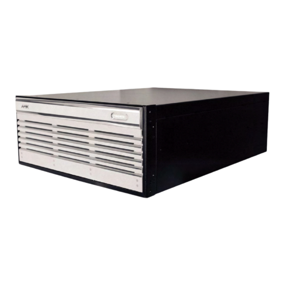
Step 4: Adding 4 MAX-AVPs to the HT Server MAX-HT servers communicate via Ethernet to up to 25 MAX-AVP Audio -Video Players (FIG. 19). In this example we will add four AVPs. FIG. 19 MAX-AVP Audio -Video Player In order to add the AVPs to the server, you'll need to know the Setup Serial key for each AVP. This Setup Serial key is printed on a decal, placed on the bottom of each AVP unit (FIG. - Page 22 Step 4: Adding 4 MAX-AVPs to the HT Server FIG. 21 MAX Admin Menu - Output Module Setup Press Enter to access the Output Module Setup dialog (FIG. 22). FIG. 22 Output Module Setup dialog 2. Select Add and press Enter to open the Add Output Module dialog (FIG. 23). FIG.
- Page 23 FIG. 24 Add AVM dialog - ENTER OUPUT NUMBER HT servers treat MAX-AVPs the same as MAX-AVM modules in terms of how these devices are added and recognized by the server. That's why the selection is named "AVM" in this dialog. 3.
- Page 24 Step 4: Adding 4 MAX-AVPs to the HT Server FIG. 27 Assign A Different Output Number To Each AVP When you're finished, you should have assigned the four AVPs to Outputs 1, 2, 3 and 4 (FIG. 28). FIG. 28 Assign The Four Avps To Outputs 1, 2, 3 And 4 The server will not allow you to assign a module to an output/zone that is already in use.
-
Page 25: Step 5: Adding The Max-Aom To The Server
Step 5: Adding the MAX-AOM to the Server Overview MAX-HT servers communicate via USB to up to 2 MAX-AOM Audio-Only Modules (FIG. 29). In this example we will add a single AOM, keeping in mind that each AOM is capable of providing up to four audio zones. - Page 26 Step 5: Adding the MAX-AOM to the Server FIG. 31 Associate Each Output To One Of The Four Audio Outputs On The AOM. 1. In the MAX Admin Menu, select: Output Module Setup (FIG. 32). FIG. 32 MAX Admin Menu - Output Module Setup 2.
-
Page 27: Adding The Aom To Server Output #5, Usb #1, Aom Audio Output #1
AOM Output # 1. 6. Enter "1" (FIG. 37). 7. Press Enter. The server will notify you that Output #5 has been added (FIG. 38). MAX HT Four-Zone System Setup Guide Step 5: Adding the MAX-AOM to the Server... - Page 28 Step 5: Adding the MAX-AOM to the Server FIG. 37 Add AOM dialog - ENTER AOM OUTPUT NUMBER FIG. 38 Notification dialog - OUTPUT #5 has been added FIG. 39 offers a visual summary of the steps performed to add the AOM to Output #5 on the Server.
-
Page 29: Adding The Aom To Server Output #6, Usb #1, Aom Audio Output #2
5. Press Enter to proceed to the ENTER AOM OUTPUT NUMBER dialog. 6. Enter a "2" here and press Enter (FIG. 43). FIG. 43 Add AOM dialog - ENTER AOM OUTPUT NUMBER MAX HT Four-Zone System Setup Guide Step 5: Adding the MAX-AOM to the Server... - Page 30 Step 5: Adding the MAX-AOM to the Server The server will notify you that Output #6 has been added. FIG. 44 Notification dialog - OUTPUT #6 has been added FIG. 45 offers a visual summary of the steps performed to add the AOM to Output #6 on the Server.
-
Page 31: Adding The Aom To Server Output #7, Usb #1, Aom Audio Output #3
5. Press Enter to proceed to the ENTER AOM OUTPUT NUMBER dialog. 6. Enter a "3" here and press Enter (FIG. 49). FIG. 49 Add AOM dialog - ENTER AOM OUTPUT NUMBER MAX HT Four-Zone System Setup Guide Step 5: Adding the MAX-AOM to the Server... - Page 32 Step 5: Adding the MAX-AOM to the Server The server will notify you that Output #7 has been added. FIG. 50 Notification dialog - OUTPUT #7 has been added FIG. 45 offers a visual summary of the steps performed to add the AOM to Output #7 on the Server.
-
Page 33: Adding The Aom To Server Output #8, Usb #1, Aom Audio Output #4
5. Press Enter to proceed to the ENTER AOM OUTPUT NUMBER dialog. 6. Enter a "4" here and press Enter (FIG. 49). FIG. 55 Add AOM dialog - ENTER AOM OUTPUT NUMBER MAX HT Four-Zone System Setup Guide Step 5: Adding the MAX-AOM to the Server... - Page 34 Step 5: Adding the MAX-AOM to the Server 7. The server will notify you that Output #8 has been added. FIG. 56 Notification dialog - OUTPUT #7 has been added FIG. 45 offers a visual summary of the steps performed to add the AOM to Output #7 on the Server.
-
Page 35: Step 6: Setting The Control Ip Address For The Server
Step 6: Setting the CONTROL IP Address For the Server Overview HT Servers come with a default IP Address of 192.168.1.30. In many residential installations, this default address will work, in which case there is no need to change it. However, in many cases, you'll need to change the IP Address, Gateway and DNS Address to make the MAX Server compatible with the network at the installation site. - Page 36 Step 6: Setting the CONTROL IP Address For the Server 1. Enter an IP Address for the MAX server and press TAB to fill in the Netmask address. 2. Press Tab again to populate the Default Gateway (IP) address. By default, MAX servers use a default Gateway address ending in ".254".
-
Page 37: Step 7: Connecting The Max-Avps
Step 7: Connecting the MAX-AVPs Overview MAX-AVPs ship with an external Power Supply (AMX PS4.4), hand-held IR remote controller and all required A/V cables. FIG. 60 MAX-AVP You'll use the A/V GB Ethernet Switch to connect the four AVPs to the HT server. - Page 38 Step 7: Connecting the MAX-AVPs 2. Connect the AVP's included power supply (FIG. 62). FIG. 62 AVP Power Supply a. Plug the power cable into the PS4.4 Power Supply. b. Plug the barrel plug from the PS4.4 into the PWR connector on the AVP. c.
- Page 39 Step 7: Connecting the MAX-AVPs FIG. 64 Four MAX-AVPs connected to the HT Server and A/V Equipment 5. Turn on the power switch on each AVP, and allow up to one minute for the AVPs to initialize. MAX HT Four-Zone System Setup Guide...
- Page 40 Step 7: Connecting the MAX-AVPs MAX HT Four-Zone System Setup Guide...
-
Page 41: Step 8: Connecting The Max-Aom
Step 8: Connecting the MAX-AOM Overview The MAX-AOM (FIG. 65) ships with an external Power Supply (5VDC, 2.4A) and all required audio and USB cables. FIG. 65 MAX-AOM - Rear Panel Connectors 1. Connect the included power supply to the AOM - Show Power Supply a. - Page 42 Step 8: Connecting the MAX-AOM 3. Connect the MAX-AOM(s) to four audio amplifiers or audio switches, using one of connector types: analog stereo, or digital audio output (FIG. 67). FIG. 67 Connect the MAX-AOM(s) to four audio amplifiers or audio switches Do not use a USB hub with MAX-HT servers or AOM modules.
-
Page 43: Testing The Max Setup
The only thing left to do is test the system by connecting an A/V device to one of the MAX-AVPs, and an Audio device to the MAX-AOM to test their output. Testing the MAX-AVP Each MAX server ships with one movie and one audio CD pre-loaded for this purpose. - Page 44 Testing the MAX Setup 3. On the remote controller, press the MAX button to access the Main Page of the AVPs on-screen user interface (FIG. 70). FIG. 70 AVP On-screen User Interface - Main Page 4. Use the arrow buttons on the remote to select Movies and press the Select button on the remote to access the Movies Page (FIG.
-
Page 45: Testing The Aom
AVP. Testing the AOM To test audio output on the AOM, you'll need to use the WinMAX software application from AMX. WinMAX allows you to control the MAX Servers via a PC residing on the CONTROL segment of the MAX network. - Page 46 Testing the MAX Setup FIG. 73 WinMAX - System Information tab 4. Type the IP Address of the MAX Server into the field labeled Server's IP Address or URL. Then click on the disk icon next to the text-entry field to save this configuration. The blank fields should fill in momentarily, indicating that the Server has been recognized.
-
Page 47: Shutting Down The Max Server
FIG. 74 WinMAX - Music tab 6. Select an output zone, select the CD Title and press the Play button at the bottom of the screen to initiate playback. Shutting Down the MAX Server The correct way to shut down the MAX server is via the Shutdown command in the MAX Admin Menu (FIG. - Page 48 Testing the MAX Setup MAX HT Four-Zone System Setup Guide...
- Page 49 Testing the MAX Setup MAX HT Four-Zone System Setup Guide...
- Page 50 It’s Your World - Take Control™ 3000 RESEARCH DRIVE, RICHARDSON, TX 75082 USA • 800.222.0193 • 469.624.8000 • 469-624-7153 fax • 800.932.6993 technical support • www.amx.com...
Need help?
Do you have a question about the MAX-AOM and is the answer not in the manual?
Questions and answers