Advertisement
Quick Links
CONTACT US FIRST
CONTACT US FIRST
sauder.com
sauder.com
sauder.com
BEFORE MAKING ANY RETURNS TO THE STORE.
BEFORE MAKING ANY RETURNS TO THE RETAILER.
sauder.com/service
Visit
Prefer the phone? Give us a ring at
Customer Service is available Monday-Friday - 9 a.m. to 5:30 p.m. EST (except holidays)
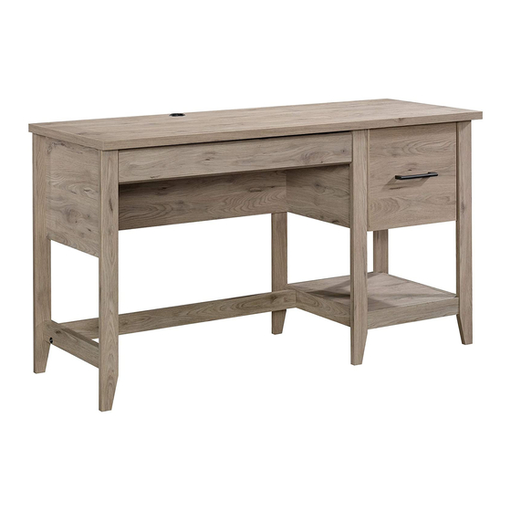
Desk
Summit Station Collection | Model 425015
Sauder.com
Share your journey!
to order replacement parts, view video assembly tips, or chat with a live rep.
1-800-523-3987
.
The original desktop.
NOTE: THIS INSTRUCTION
BOOKLET CONTAINS IMPORTANT
SAFETY INFORMATION.
PLEASE READ AND KEEP FOR
FUTURE REFERENCE.
English pg 1-28
Français pg 29-32
Español pg 33-36
Lot # 533064
Purchased: __________________
09/26/19
Advertisement

Related Manuals for Sauder Summit Station 425015


Summary of Contents for Sauder Summit Station 425015
- Page 1 CONTACT US FIRST CONTACT US FIRST sauder.com sauder.com sauder.com BEFORE MAKING ANY RETURNS TO THE STORE. BEFORE MAKING ANY RETURNS TO THE RETAILER. sauder.com/service Visit to order replacement parts, view video assembly tips, or chat with a live rep. 1-800-523-3987 Prefer the phone? Give us a ring at Customer Service is available Monday-Friday - 9 a.m.
- Page 2 Assembly Tools Required Part Identifi cation No. 2 Phillips Screwdriver Tip Shown Actual Size Hardware Identifi cation Assembly Steps 6-28 Hammer Not actual size Français 29-32 Español 33-36 Skip the power trip. Safety 37-38 This time. Warranty Page 2 425015 www.sauder.com/service...
- Page 3 FILE DRAWER BACK (1) DESK LEFT FRONT LEG (1) D266 PENCIL RIGHT DRAWER SIDE (1) DESK LEFT REAR LEG (1) D267 PENCIL LEFT DRAWER SIDE (1) RIGHT BOTTOM MOLDING (1) TOP (1) D716 D266 D540 D541 D267 www.sauder.com/service 425015 Page 3...
- Page 4 CAM DOWEL - 20 CAM SCREW - 18 WOOD DOWEL - 11 CROSS SLOTTED DOWEL - 2 PULL - 1 EXTENSION BRACKET - 2 GLUE - 1 GROMMET CAP - 1 GROMMET - 1 CAM COVER - 6 Page 4 425015 www.sauder.com/service...
- Page 5 30S BLACK 1-9/16" FLAT HEAD SCREW - 8 BLACK 7/8" LARGE HEAD SCREW - 4 BLACK 7/8" MACHINE SCREW - 2 103S BLACK 2-3/8" FLAT HEAD BOLT - 2 113S BLACK 1-15/16" FLAT HEAD SCREW - 2 www.sauder.com/service 425015 Page 5...
- Page 6 Look for this icon. It means a Step 1 video assembly tip is available at www.sauder.com/service/tips Assemble your unit on a carpeted fl oor or on the empty carton to å avoid scratching your unit or the fl oor. Push twenty HIDDEN CAMS (1F) into the ENDS (A and B), å...
- Page 7 ENDS (A and B), UPRIGHT (D), LEFT BRACE (G), and BOTTOM MOLDINGS (H and S). Arrow (18 used) Arrow Arrow Hole The arrow in the HIDDEN CAM must point toward the hole in the edge of the board. www.sauder.com/service 425015 Page 7...
- Page 8 GLUE (54M). Then, insert the WOOD DOWEL (15F) into the hole. Wipe away the excess GLUE. (18 used) Caution Inspect the parts thoroughly before assembling. Disassembly of glued parts is extremely diffi cult. Fill the holes 1/4 to 1/2 full with GLUE. Page 8 425015 www.sauder.com/service...
- Page 9 Disassembly of glued CAM DOWELS parts is extremely diffi cult. f a c S u r w i t h D E N Surface H I D with HIDDEN CAMS These surfaces should be even. www.sauder.com/service 425015 Page 9...
- Page 10 Edge with CAM DOWELS S u r f a c w i t h H I D D E N These surfaces The holes are should be even. Surface closer to this edge. with HIDDEN CAMS Page 10 425015 www.sauder.com/service...
- Page 11 Edge with CAM DOWELS f a c S u r w i t h D E N Surface H I D with HIDDEN CAMS These surfaces should be even. This hole must be here. www.sauder.com/service 425015 Page 11...
- Page 12 Push the black lever in and pull the SLIDE from the RAIL. GOLD 5/16" FLAT HEAD SCREW Open end (4 used for the RAILS) These holes must be here. Open end These holes must be here. Page 12 425015 www.sauder.com/service...
- Page 13 Fasten the CABINET LEFT (35GB) to the LEFT END (B). Use two GOLD å 5/16" FLAT HEAD SCREWS (3S) through holes #1 and #3. Roller end GOLD 5/16" FLAT HEAD SCREW (4 used for the RAILS) BLACK 9/16" LARGE HEAD SCREW (4 used for the BRACKETS) Roller end www.sauder.com/service 425015 Page 13...
- Page 14 Tighten Risk of damage or Arrow injury. HIDDEN CAMS must be completely Arrow Maximum tightened. HIDDEN 210 degrees CAMS that are not completely tightened may loosen, and parts may separate. To Minimum completely tighten: 190 degrees Page 14 425015 www.sauder.com/service...
- Page 15 Meet Part (T). This component has been engineered to be lighter, stronger, faster… well ok. Not technically faster. But defi nitely makes for a sturdier Desk that’ s easier to assemble and friendlier to the environment. www.sauder.com/service 425015 Page 15...
- Page 16 SIDE SKIRTS. e l s d o w t e d s l o t i t h f a c S u r 103S BLACK 2-3/8" FLAT HEAD BOLT (1 used for the LONG BRACE) Page 16 425015 www.sauder.com/service...
- Page 17 Fill the holes 1/4 to 1/2 full with GLUE. Caution Inspect the parts thoroughly before assembling. Disassembly of glued parts is extremely diffi cult. 103S 103S BLACK 2-3/8" FLAT HEAD BOLT (1 used for the LONG BRACE) www.sauder.com/service 425015 Page 17...
- Page 18 Disassembly of glued parts is extremely diffi cult. NOTE: Do not tighten in this step. Finished edge f a c S u r w i t h D E N H I D Finished edge Page 18 425015 www.sauder.com/service...
- Page 19 MOLDING (H). Tighten two HIDDEN CAMS. Minimum *U.S. Patent No. 5,499,886 å 190 degrees Notched edge These surfaces Notched edge should be even. The groove is closer to this edge. The groove is closer to this edge. www.sauder.com/service 425015 Page 19...
- Page 20 Fill the holes 1/4 to 1/2 full with GLUE. Caution Inspect the parts thoroughly before assembling. Disassembly of glued parts is extremely diffi cult. NOTE: Tighten two HIDDEN CAMS to fasten the BACK (M) to the UPRIGHT (D). Page 20 425015 www.sauder.com/service...
- Page 21 (4 used in this step) D266 D540 D267 D541 Be sure the DRAWER BOTTOM inserts into the DRAWER BLACK 7/8" LARGE HEAD SCREW BOX groove. (4 used for the DRAWER FRONT) D541 The holes are closer to this edge. www.sauder.com/service 425015 Page 21...
- Page 22 DRAWER SIDE (D266) and the DRAWER LEFT (35GD) to the PENCIL LEFT DRAWER SIDE (D267). Use four GOLD 5/16" FLAT HEAD SCREWS (3S) through holes #1 and #3. Roller end D267 Roller end D266 GOLD 5/16" FLAT HEAD SCREW (4 used for the SLIDES) Page 22 425015 www.sauder.com/service...
- Page 23 Fasten the FILE DRAWER BACK (D78) to the FILE DRAWER SIDES (D14 and D15). å Use four BLACK 1-9/16" FLAT HEAD SCREWS (30S). NOTE: Be sure the FILE DRAWER BOTTOM (D716) inserts into the groove of the å FILE DRAWER BACK (D78). www.sauder.com/service 425015 Page 23...
- Page 24 SLIDES with holes in DRAWER SIDES Open end Open end BLACK 7/8" MACHINE SCREW (2 used for the PULL) Drawer Slide GOLD 5/16" FLAT HEAD SCREW (4 used for the SLIDES) Center the screw in the oval hole. Page 24 425015 www.sauder.com/service...
- Page 25 The drawer will push in hard until it is all the way in, then it will slide in and out easier. Place the roller on the SLIDE behind the roller on the RAIL. www.sauder.com/service 425015 Page 25...
- Page 26 Step 21 Insert the GROMMET (10P) and GROMMET CAP (1P) into å the large hole in the TOP (T). Page 26 425015 www.sauder.com/service...
- Page 27 Step 22 Using your hammer, gently tap a CAM COVER (75P) onto å each visible HIDDEN CAM. 25 lbs. (6 used) To cover HIDDEN CAMS www.sauder.com/service 425015 Page 27...
- Page 28 This completes assembly. Clean with a damp cloth. Wipe dry. å And to celebrate, why not share your success story at sauder.com or Loosen screw #3 a 1/4 turn, turn the cam a 1/4 turn maximum in both the clockwise and counter-clockwise directions to make adjustments, and then tighten screw #3.
- Page 29 DESCRIPTION QUANTITÉ conserver le livret pour future référence. Pour EXTRÉMITÉ DROITE ..........1 35GA ÉLÉMENT DROITE............1 contacter Sauder en EXTRÉMITÉ GAUCHE ..........1 35GB ÉLÉMENT GAUCHE ...........1 ce qui concerne cet B51 FOND DE TIROIR À CRAYONS ......1 35GC TIROIR DROIT ..............1 élément, faire référence...
- Page 30 Fixer les PIEDS (L et P) à l'EXTRÉMITÉ DROITE (A) et à la l'excentrique escamotable de 210 degrés. MOULURE DROITE DU DESSOUS (S). Serrer six EXCENTRIQUES ESCAMOTABLES. REMARQUE : Placer la MOULURE DROITE DU DESSOUS (S) exactement comme l'indique le schéma. Page 30 425015 www.sauder.com/service...
- Page 31 Fixer la MOULURE GAUCHE DU DESSOUS (H) à l’ENTRETOISE LONGUE (K). Utiliser un BOULON TÊTE PLATE 60 mm NOIRE (103S). Fixer le MONTANT (D) au VOILE DE FOND (C). Utiliser deux VIS TÊTE PLATE 49 mm NOIRES (113S). www.sauder.com/service 425015 Page 31...
- Page 32 TIROIR POUR DOSSIERS (D14 et D15). Utiliser quatre VIS TÊTE PLATE 8 mm DORÉES (3S) à travers les trous nº 1 et nº 3. REMARQUE : La tête de vis dans l'EXCENTRIQUE doit être visible à travers le trou fendu dans la COULISSE. Page 32 425015 www.sauder.com/service...
- Page 33 EXTREMO IZQUIERDO ..........1 35GB GABINETE IZQUIERDO ...........1 necesita ponerse en B51 FONDO DE CAJÓN PARA LÁPICES .....1 35GC CAJÓN DERECHO ............1 contacto con Sauder en VELO DE FONDO ............1 35GD CAJÓN IZQUIERDO ...........1 cuanto a esta unidad, PARAL ...................1 (JUEGO DE EXTENSIÓN SE MUESTRA POR SEPARADO) refi...
- Page 34 Fije las PATAS (L y P) al EXTREMO DERECHO (A) y a la MOLDURA excéntrico escondido 210 grados. DERECHA DE FONDO (S). Apriete seis EXCÉNTRICOS ESCONDIDOS. NOTA: Coloque la MOLDURA DERECHA DE FONDO (S) exactamente como se muestra. Page 34 425015 www.sauder.com/service...
- Page 35 Fije la MOLDURA IZQUIERDA DE FONDO (H) a la RIOSTRA LARGA (K). Utilice uno PERNO NEGRO DE CABEZA PERDIDA de 60 mm (103S). Fije el PARAL (D) al VELO DE FONDO (C). Utilice dos TORNILLOS NEGROS DE CABEZA PERDIDA de 49 mm (113S). www.sauder.com/service 425015 Page 35...
- Page 36 Fije las CORREDERAS DE EXTENSIÓN (35MC) a los LADOS DE CAJÓN DEL ARCHIVERO (D14 y D15). Utilice cuatro TORNILLOS DORADOS DE CABEZA PERDIDA de 8 mm (3S) a través de los agujeros No. 1 y No. 3. Page 36 425015 www.sauder.com/service...
- Page 37 à Les téléviseurs peuvent être particulièrement un téléviseur. cet eff et. lourds. De plus, le poids et l’emplacement du tube image ont tendance à rendre les téléviseurs instables et enclins à tomber vers l’ a vant. www.sauder.com/service 425015 Page 37...
- Page 38 Además, el peso y la ubicación del tubo de imagen tienden a causar la inestabilidad de televisores y propensa a volcarse hacia adelante. Page 38 425015 www.sauder.com/service...
- Page 39 à compter de la date d'achat la première fois et qui sont signalés à Sauder dans les limites de couverture de la contre tout défaut de matériaux ou de fabrication des composantes de mobilier Sauder.
- Page 40 BEFORE MAKING ANY RETURNS TO THE RETAILER. Dear Valued Customer: So, how did it go? Thanks so much for choosing Sauder® furniture. I hope the Set a world record for speed? purchase and assembly process was a positive experience Feeling good about yourself? and you feel good about the furniture you just built.
Need help?
Do you have a question about the Summit Station 425015 and is the answer not in the manual?
Questions and answers