Advertisement
Available languages
Available languages
Quick Links
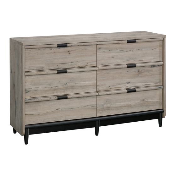
Dresser
WARNING
CHOKING HAZARD - Small Parts
Not for children under 3 years.
Adult assembly required.
NOTE: THIS INSTRUCTION
BOOKLET CONTAINS IMPORTANT
SAFETY INFORMATION.
PLEASE READ AND KEEP FOR
FUTURE REFERENCE.
English pg 1-23
Français pg 24-27
Español pg 28-31
Advertisement

Subscribe to Our Youtube Channel
Related Manuals for Sauder 425024


Summary of Contents for Sauder 425024
- Page 1 WARNING CHOKING HAZARD - Small Parts Not for children under 3 years. Adult assembly required. Dresser NOTE: THIS INSTRUCTION BOOKLET CONTAINS IMPORTANT SAFETY INFORMATION. PLEASE READ AND KEEP FOR FUTURE REFERENCE. English pg 1-23 Français pg 24-27 Español pg 28-31...
-
Page 2: Table Of Contents
Table of Contents Assembly Tools Required Part Identification No. 2 Phillips Screwdriver Tip Shown Actual Size Hardware Identification Assembly Steps 6-23 Hammer Français 24-27 Not actual size Español 28-31 Safety 32-34 Warranty Part Identification å While not all parts are labeled, some of the parts will have a label or an inked letter on the edge to help distinguish similar parts from each other. - Page 3 Now you know Part Identification our ABCs. D985 D985 Page 3...
- Page 4 Hardware Identification å Screws are shown actual size. You may receive extra hardware with your unit. 10A SLIDE CAM - 12 35AA UNIVERSAL CABINET RAIL - 12 35AC DRAWER RIGHT - 6 35AD DRAWER LEFT - 6 ANGLE BRACKET - 6 182K PULL - 6 HIDDEN CAM - 16...
- Page 5 Hardware Identification å Screws are shown actual size. You may receive extra hardware with your unit. 3S GOLD 5/16" FLAT HEAD SCREW - 48 BLACK 9/16" LARGE HEAD SCREW - 12 BLACK 1-1/4" FLAT HEAD SCREW - 24 BLACK 2-1/4" FLAT HEAD SCREW - 2 30S BLACK 1-9/16"...
- Page 6 190 degrees Step 1 Look for this icon. It means a video assembly tip is available at www.sauder.com/service/tips Find the numbered video or scan the QR code. å Assemble your unit on a carpeted floor or on the empty carton to avoid scratching your unit or the floor.
-
Page 7: Left End
Step 2 å Fasten three UNIVERSAL CABINET RAILS* (35AA) to the LEFT END (B). Use six GOLD 5/16" FLAT HEAD SCREWS (3S) Just think. The sooner through holes #1 and #3. you do this, the sooner you do something else. å... - Page 8 Step 3 å Open the FURNITURE TIPPING RESTRAINT KIT (97) and Caution fasten the SAFETY STRAP to the TOP (D). Use the short Do not stand the unit upright without the screw provided. BACK fastened. The unit may collapse. å NOTE: Position the SAFETY STRAP exactly as shown.
- Page 9 Step 4 å Push two HIDDEN CAMS (1F) into the UPRIGHT (C). Then, insert the metal end of a CAM DOWEL (2F) into each HIDDEN CAM. Arrow Metal end Do not tighten the HIDDEN CAMS in this step. Page 9...
- Page 10 Step 5 å Fasten six UNIVERSAL CABINET RAILS* (35AA) to the UPRIGHT (C). Use twelve GOLD 5/16" FLAT HEAD SCREWS (3S) through holes #1 and #3. å *patent pending glide system Glide end GOLD 5/16" FLAT HEAD SCREW (12 used in this step) Glide end Page 10...
- Page 11 Step 6 å Fasten the UPRIGHT (C) to the TOP (D). Tighten two HIDDEN CAMS. Finished edge f a c S u r w i t h D E N H I D Page 11...
- Page 12 Step 7 å Push four HIDDEN CAMS (1F) into the BOTTOM (E). Then, insert the metal end of a CAM DOWEL (2F) into each HIDDEN CAM. Arrow Metal end Do not tighten the HIDDEN CAMS in this step. Part (E). Another sturdier, easier, friendlier component! Arrow...
- Page 13 Step 8 å Fasten six FEET (L) to the BOTTOM (E) using the exact holes shown. Use six BLACK 2-3/8" FLAT HEAD BOLTS (103S). 103S BLACK 2-3/8" FLAT HEAD BOLT (6 used in this step) Page 13...
- Page 14 Step 9 å Fasten the BOTTOM (E) to the LEFT END (B). Tighten two HIDDEN CAMS. Now might be a good time to refresh å Fasten the BOTTOM (E) to the UPRIGHT (C). Use two your drink. BLACK 2-1/4" FLAT HEAD SCREWS (26S). Rounded edge Finished edge BLACK 2-1/4"...
- Page 15 Step 10 å Push two HIDDEN CAMS (1F) into the RIGHT END (A). Then, insert the metal end of a CAM DOWEL (2F) into each HIDDEN CAM. å Fasten three UNIVERSAL CABINET RAILS* (35AA) to the RIGHT END (A). Use six GOLD 5/16" FLAT HEAD SCREWS (3S) through holes #1 and #3.
- Page 16 Step 11 å Fasten the RIGHT END (A) to the TOP (D) and BOTTOM (E). Tighten four HIDDEN CAMS. i t h o f a c S u r D E N H I D Page 16...
- Page 17 Step 12 å Fasten six ANGLE BRACKETS (5G) to the SKIRTS (G). Use six BLACK 9/16" LARGE HEAD SCREWS (1S). å NOTE: Be sure the edges of the ANGLE BRACKETS are even with the edges of the SKIRTS. å Fasten the SKIRTS (G) to the BOTTOM (E). Use six BLACK 9/16"...
- Page 18 Step 13 å Carefully turn your unit over onto its front edges. Unfold Caution the BACK (F) and lay it over your unit. Do not stand the unit upright without the å A perforation in the BACK (F) has been provided for BACK fastened.
-
Page 19: D985 Drawer Bottom
Step 14 The tabs should insert freely With the palm of your hand, into the slots. Gently tilt the tap the DRAWER BOTTOM DRAWER SIDES side to side down into the groove. until the tabs slip into the slots. U n fi n i s h s u r f a c... - Page 20 Step 15 å Insert a SLIDE CAM (10A) into the DRAWER SIDES (D30 and D31). å Fasten the DRAWER RIGHT (35AC) to the RIGHT DRAWER SIDE (D30) and the DRAWER LEFT (35AD) to the LEFT DRAWER SIDE (D31). Use four GOLD 5/16" FLAT HEAD SCREWS (3S) through holes #1 and #2. å...
- Page 21 Step 16 å Fasten a PULL (182K) to the RIGHT DRAWER FRONT (I). Use two BLACK 7/8" MACHINE SCREWS (37S). Hey! It's starting to look å NOTE: Do not completely tighten the SCREWS in the PULL. like something! å Fasten two DRAWER FRONT MOLDINGS (J) to the RIGHT DRAWER FRONT (I).
- Page 22 Step 17 å Carefully stand your unit upright in its final location. We recommend using the SAFETY STRAP for added stability. å NOTE: Do not turn the SAFETY DRYWALL ANCHOR into a wall stud. If you prefer to fasten the SAFETY STRAP to a wall stud, go to your local hardware store for proper hardware.
- Page 23 Step 18 å To insert the drawer into your unit, tip the front of the drawer down and drop the glides on the drawer behind the glides on the unit. Lift the front of the drawer up and slide it into the unit. å...
- Page 24 Step 19 å To make adjustments to the drawer, loosen SCREW #2 in the SLIDES a 1/4 turn, then turn the cam clockwise or counter- clockwise. Notice how the drawer raises or lowers as you turn the cam. By adjusting the drawer this way, it will help the DRAWER FRONT line up better when closed.
- Page 25 Commode Utilisez les instructions d’ a ssemblage en français avec les NOUS CONTACTER EN PREMIER schémas étape par étape du manuel d’instruction en anglais. AVANT D'EFFECTUER TOUT RETOUR AU MAGASIN. Chaque étape en français correspond à la même étape en Nous faisons de notre mieux pour nous assurer que votre meuble anglais.
- Page 26 Guide d'utilisation de la visserie ÉTAPE 4 UTILISATION DE LA EXCENTRIQUE ESCAMOTABLE ET DE LA Ne pas serrer les EXCENTRIQUES ESCAMOTABLES dans cette étape. CHEVILLE D'EXCENTRIQUE Enfoncer deux EXCENTRIQUES ESCAMOTABLES (1F) dans 1. Enfoncer un EXCENTRIQUE ESCAMOTABLE dans la partie. La le MONTANT (C).
- Page 27 ÉTAPE 10 ÉTAPE 14 Ne pas serrer les EXCENTRIQUES ESCAMOTABLES dans cette étape. 1. Insérer les CÔTÉS DE TIROIR (D30 et D31) en biseau dans la fente dans chaque extrémité du DEVANT DE TIROIR DROIT (I). Enfoncer deux EXCENTRIQUES ESCAMOTABLES (1F) dans l’EXTRÉMITÉ...
- Page 28 ÉTAPE 17 ÉTAPE 18 Relever, avec précaution, l'élément dans sa position verticale et Pour insérer le tiroir dans l’unité, incliner le devant du tiroir vers le placer l'élément dans son emplacement final. Il est recommandé bas et faire tomber les coulisses du tiroir derrière les coulisses de d'utiliser la SANGLE DE SÉCURITÉ...
- Page 29 Modelo 425024 Cómoda Use estas instrucciones de ensamblaje en español junto con las CONTÁCTENOS PRIMERO figuras paso-a-paso provistas en el folleto inglés. Cada paso en ANTES DE HACER DEVOLUCIONES A LA TIENDA. español corresponde al mismo paso en inglés. Compare la “Lista Tratamos de asegurar que su mueble llega en condición excelente.
- Page 30 Guía de uso de herrajes PASO 4 CÓMO UTILIZAR EL EXCÉNTRICO ESCONDIDO Y No apriete los EXCÉNTRICOS ESCONDIDOS en este paso. EL PASADOR DE EXCÉNTRICO Empuje dos EXCÉNTRICOS ESCONDIDOS (1F) en el PARAL (C). 1. Empuje un EXCÉNTRICO ESCONDIDO dentro de la parte. La A continuación, inserte el extremo de metal de un PASADOR DE flecha en el EXCÉNTRICO ESCONDIDO debe apuntar hacia el EXCÉNTRICO (2F) dentro de cada EXCÉNTRICO ESCONDIDO.
- Page 31 PASO 9 PASO 13 Fije el FONDO (E) al EXTREMO IZQUIERDO (B). Apriete dos Precaución EXCÉNTRICOS ESCONDIDOS. No coloque la unidad en posición vertical hasta que se fije el Fije el FONDO (E) al PARAL (C). Utilice dos TORNILLOS NEGROS DORSO.
- Page 32 PASO 15 PASO 18 Inserte un EXCÉNTRICO DE CORREDERA (10A) en los LADOS Para insertar el cajón en la unidad, incline la parte delantera del DE CAJÓN (D30 y D31). cajón hacia abajo y deje que los corrimientos del cajón caigan detrás de los corrimientos de la unidad.
- Page 33 WARNING Please use your furniture correctly and safely. Improper use can cause safety hazards, or damage to your furniture or household items. Carefully read the following safety information. Death or serious injury may occur when children climb on furniture. A remote control, toys or other items placed on the furniture may encourage a child to climb on the furniture which could cause it to tip-over and result in serious injury or death.
- Page 34 ADVERTENCIA Por favor use el mobiliario correcta y seguramente. El mal uso puede causar riesgos de seguridad o daño a las unidades o artículos domésticos. Lea cuidadosamente la siguiente información de seguridad. Pueden suceder lesiones graves o la muerte cuando los niños se suben en los muebles. Un control remoto, juguetes u otros artículos colocados en los muebles pueden alentar a un niño a subirse en el mueble, lo cual podría causar que se derribe y resultaría en lesiones graves o la muerte.
- Page 35 5-YEAR LIMITED WARRANTY 1. Provides limited warranty coverage to the original purchaser of this product for a 4. This Warranty applies only to warranted defects that fi rst arise and are reported period of fi ve years from the date of purchase against defects in materials or to within the warranty coverage period.
Need help?
Do you have a question about the 425024 and is the answer not in the manual?
Questions and answers