Advertisement
Quick Links
Overview
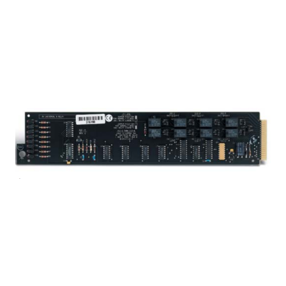
Devices that require a simple momentary or latching contact closure can be
controlled with the AXC-REL8 Universal Eight Relay Card (FIG. 1). This
card can operate up to 8 relay-controlled functions; cards can be linked
together, allowing a larger number of functions. Adjacent relays on the card
may be selectively commoned to reduce device wiring.
FIG. 1
AXC-REL8 Universal Eight Relay Card (side view)
Specifications
The table below provides specification information for the AXC-REL8
(FG715).
Specifications
Power
• 150 mA, 12 VDC
Consumption:
Contact
• 8 per card
Closures:
Relays:
• Single pole double throw (SPDT).
• Each relay is individually assignable as normally open
(NO) or normally closed (NC) via jumpers provided on the
card.
Jumpers:
• JP1: Installed between center pin and NC, relay 1 is
Normally Closed; installed between center pin and NO,
relay 1 is Normally Open.
• JP2: Same as JP1 for relays 2 - 8, respectively a jumper
must be in one of these locations for each relay used.
LEDs:
• CR1 - 8: Indicates energized condition of corresponding
relay
Contact Rating:
• 1 A @ 24 VAC / 28 VDC
• 750 mA MAX resistive load.
Connections
The table below lists the AXC-REL8 pinout connectors.
Pinout Connectors
Pinout
Description
1
Common #1
2
Contact #1
3
Common #2
4
Contact #2
5
Common #3
6
Contact #3
7
Common #4
8
Contact #4
9
Common #5
10
Contact #5
11
Common #6
12
Contact #6
13
Common #7
14
Contact #7
15
Common #8
16
Contact #8
AXC-REL8
Commons
The table below lists the commons for the AXC-REL8 if installed in the On
position.
Commons
Commons
Description
CO1 - 2
Connects Common #1 to Common #2.
CO2 - 3
Connects Common #2 to Common #3.
CO3 - 4
Connects Common #3 to Common #4.
CO4 - 5
Connects Common #4 to Common #5.
CO5 - 6
Connects Common #5 to Common #6.
CO6 - 7
Connects Common #6 to Common #7.
CO7 - 8
Connects Common #7 to Common #8.
Relay Status LED Indicators
The table below provides a description for the illumination of each relay
LED. Refer to FIG. 2 for a visual reference of LED locations.
Relay Status LEDs
Relay LED #
Description
CR1 (top LED)
Indicates the energized condition of relay 1.
CR2
Indicates the energized condition of relay 2.
CR3
Indicates the energized condition of relay 3.
CR4
Indicates the energized condition of relay 4.
CR5
Indicates the energized condition of relay 5.
CR6
Indicates the energized condition of relay 6.
CR7
Indicates the energized condition of relay 7.
CR8
Indicates the energized condition of relay 8.
Top LED
FIG. 2
AXC-REL8 Relay status locations
Quick Start Guide
Universal Eight Relay Card
Advertisement

Related Manuals for AMX AXC-REL8


Summary of Contents for AMX AXC-REL8
- Page 1 Common #8 Contact #8 Quick Start Guide AXC-REL8 Universal Eight Relay Card Commons The table below lists the commons for the AXC-REL8 if installed in the On position. Commons Commons Description CO1 - 2 Connects Common #1 to Common #2.
- Page 2 060-004-2692 2/05 ©2005 AMX Corporation. All rights reserved. The AMX logo is a trademark of AMX Corporation. AMX reserves the right to alter specifications without notice at any time. 3000 RESEARCH DRIVE, RICHARDSON, TX 75082 • 800.222.0193 • fax 469.624.7153 • technical support 800.932.6993 • www.amx.com...