Table of Contents
Advertisement
Quick Links
Advertisement
Table of Contents

Related Manuals for Motorola VP22A/IH1


Summary of Contents for Motorola VP22A/IH1
- Page 1 VP22 microATX Motherboard Installation and Use VP22A/IH1 June 2001 Edition...
- Page 2 © Copyright 2001 Motorola Inc. All rights reserved. Printed in the United States of America. ® Motorola and the Motorola symbol are registered trademarks of Motorola, Inc. ® ™ Pentium is a registered trademark and Celeron is a trademark of Intel Corporation.
- Page 3 The safety precautions listed below represent warnings of certain dangers of which Motorola is aware. You, as the user of the product, should follow these warnings and all other safety precautions necessary for the safe operation of the equipment in your operating environment.
- Page 4 Flammability All Motorola PWBs (printed wiring boards) are manufactured with a flammability rating of 94V-0 by UL-recognized manufacturers. EMI Caution This equipment generates, uses and can radiate electromagnetic energy. It Caution may cause or be susceptible to electromagnetic interference (EMI) if not installed and used with adequate EMI protection.
- Page 5 While reasonable efforts have been made to assure the accuracy of this document, Motorola, Inc. assumes no liability resulting from any omissions in this document, or from the use of the information obtained therein. Motorola reserves the right to revise this document and to make changes from time to time in the content hereof without obligation of Motorola to notify any person of such revision or changes.
- Page 6 If the documentation contained herein is supplied, directly or indirectly, to the U.S. Government, the following notice shall apply unless otherwise agreed to in writing by Motorola, Inc. Use, duplication, or disclosure by the Government is subject to restrictions as set forth in subparagraph (b)(3) of the Rights in Technical Data clause at DFARS 252.227-7013 (Nov.
-
Page 7: Table Of Contents
Contents About This Manual Overview of Contents ....................xiii Comments and Suggestions ..................xiv Conventions Used in This Manual ................xv CHAPTER 1 Hardware Preparation and Installation Introduction ......................1-1 Overview ........................1-2 Unpacking Guidelines ....................1-2 Hardware Configuration ................... 1-3 VP22 Motherboard Preparation ................ 1-3 CMOS Clear Header (JP1) ................ - Page 8 Preparation ......................B-3 Measuring Junction Temperature ..............B-4 Measuring Case Temperature ................B-4 Measuring Local Air Temperature ..............B-6 APPENDIX C Related Documentation Motorola Computer Group Documents ..............C-1 Manufacturers’ Documents ..................C-1 Related Specifications ..................... C-2 URLs ........................C-3 viii...
- Page 9 List of Figures Figure 1-1. VP22 Motherboard Layout ..............1-4 Figure 2-1. VP22 Block Diagram ................2-1 Figure B-1. Thermally Significant Components—Primary Side ......B-3 Figure B-2. Mounting a Thermocouple Under a Heatsink ........B-5 Figure B-3. Measuring Local Air Temperature ............B-6...
- Page 11 Table 3-23. Audio LINE OUT Connector (PH3) ..........3-10 Table A-1. VP22 Power Requirements ..............A-1 Table A-2. VP22 Specifications ................A-2 Table B-1. Thermally Significant Components ............B-2 Table C-1. Motorola Computer Group Documents ..........C-1 Table C-2. Manufacturers’ Documents ..............C-2 Table C-3. Related Specifications ................C-3...
-
Page 13: Overview Of Contents
About This Manual This manual provides information on hardware preparation and installation for the VP22 microATX motherboard (hereinafter referred to as the VP22). In addition, it also provides the features and specifications applicable to the motherboard. For BIOS information and programming details for the VP22 motherboard, refer to the VP22 microATX Motherboard BIOS and Programmer’s Reference Guide, listed in Appendix C, Related... -
Page 14: Comments And Suggestions
Documentation, lists all documentation related to the VP22 motherboard. Comments and Suggestions Motorola welcomes and appreciates your comments on its documentation. We want to know what you think about our manuals and how we can make them better. Mail comments to:... -
Page 15: Conventions Used In This Manual
Conventions Used in This Manual The following typographical conventions are used in this document: bold is used for user input that you type just as it appears; it is also used for commands, options and arguments to commands, and names of programs, directories and files. -
Page 17: Introduction
1Hardware Preparation and Installation Introduction The VP22 is a standard microATX form factor motherboard that supports ® ™ a single Pentium III or Celeron processor (66/100/133 MHz processor- side bus) on the Intel 815E chipset with integrated graphics. This ® ®... -
Page 18: Overview
Hardware Preparation and Installation Overview The following table lists the things you will need to do before you can use this board and tells where to find the information you need to perform each step. Be sure to read this entire chapter, including all cautions and warnings, before you begin. -
Page 19: Hardware Configuration
Chapter 3, Connector Pin Assignments. Table 1-2. VP22 Jumper Settings Jumper Function Settings CMOS Clear [1-2] Normal CMOS clear Note Items in brackets are factory default settings. The VP22 is factory tested and shipped with the configuration described in the following section. http://www.motorola.com/computer/literature... -
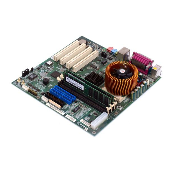
Page 20: Figure 1-1. Vp22 Motherboard Layout
Hardware Preparation and Installation DIMM1 DIMM2 DIMM3 CN11 CN10 CN15 CN12 CN13 CN14 CN16 CN17 Figure 1-1. VP22 Motherboard Layout Computer Group Literature Center Web Site... -
Page 21: Cmos Clear Header (Jp1)
JP1 back to its default setting, pins 1-2. 3. Power on the system. 4. After powering on the system, press <Del> to enter the BIOS setup utility. Refer to the VP22 microATX Motherboard BIOS and Programmer’s Reference Guide for more information. http://www.motorola.com/computer/literature... -
Page 22: Hardware Installation
Installation Preliminaries This section applies to all hardware installations you may perform on VP22 motherboards. Motorola strongly recommends that you use an antistatic wrist strap and a Use ESD conductive foam pad when installing or upgrading a system. Electronic components, such as disk drives, computer boards, and memory modules, can be extremely sensitive to electrostatic discharge (ESD). -
Page 23: Vp22 Motherboard Installation
Avoid touching areas of integrated circuitry; static discharge can damage these circuits. Caution 5. Set the VP22 motherboard on the chassis standoffs and start the screw(s) provided into the standoffs, without tightening them completely. 6. With all screws in place, tighten them snugly. http://www.motorola.com/computer/literature... -
Page 24: Dimm Memory Installation
Hardware Preparation and Installation DIMM Memory Installation DIMM modules install into the DIMM 1, DIMM 2 and DIMM 3 sockets on the VP22 motherboard. To install the DIMM memory, refer to the procedure and figure below. 1. Attach an ESD strap to your wrist. Attach the other end of the ESD strap to the chassis as a ground (refer to Installation Preliminaries on page... -
Page 25: Pci Adapter Board Installation (Optional)
VP22 motherboard. To install PCI adapter boards, proceed as follows: 1. Attach an ESD strap to your wrist. Attach the other end of the ESD strap to the chassis as a ground (refer to Installation Preliminaries on http://www.motorola.com/computer/literature... - Page 26 Hardware Preparation and Installation page 1-6). The ESD strap must be secured to your wrist and to ground throughout the procedure. 2. Perform an operating system shutdown. Turn the AC or DC power off and remove the AC cord or DC power lines from the system. Remove chassis or system cover(s) as necessary for access to the motherboard.
-
Page 27: Connection To Peripherals
VP22, you are ready to connect peripherals and apply power to the board. Figure 1-1 on page 1-4 shows the locations of the various cable connectors. They are also listed in Table 1-3 with the rest of the connectors. http://www.motorola.com/computer/literature 1-11... -
Page 28: Table 1-3. Vp22 Board Connectors
Hardware Preparation and Installation For the pin assignments of the connectors listed, refer to Chapter 3, Connector Pin Assignments. Table 1-3. VP22 Board Connectors Connector Function I/O Panel Connectors SVGA panel connector COM1 serial port panel connector Keyboard/mouse panel connectors Parallel port panel connector Dual Universal Serial Bus (USB) panel connectors Ethernet panel connector... -
Page 29: Completing The Installation
Replace the chassis or system cover, reconnect the system to the AC or DC power source, and turn the equipment power on. Processor Removal and Replacement Microprocessors in Motorola board products are factory-installed and tested to ensure proper operation under board-specific BIOS software within specified power and cooling requirements. Field replacement of the processor is not recommended. -
Page 30: Replacing Lithium Batteries
Hardware Preparation and Installation Motorola is continually improving its products to use the latest processor speeds and technologies as they become available. If your application requires a different processor, consult your local Motorola representative. Replacing Lithium Batteries Follow these safety rules for proper battery operation and to reduce equipment and personal injury hazards when handling lithium batteries. - Page 31 3. Note the battery polarity and press the new battery into the socket. Note When the battery is in the socket, no soldering is required. 4. Recycle or dispose of the old battery according to local regulations and manufacturer’s instructions. http://www.motorola.com/computer/literature 1-15...
-
Page 33: Introduction
2Functional Description Introduction This chapter describes the VP22 motherboard on a block diagram level. General Description provides an overview of the VP22, followed by a detailed description of several blocks of circuitry. Figure 2-1 shows a block diagram of the overall board architecture. Socket 370 Processor Three 168-pin, 3.3V... -
Page 34: Features
Functional Description Features The following table lists the features of the VP22 motherboard. Table 2-1. VP22 Motherboard Features Summary Feature Description Microprocessor –Single Intel PGA370 socket Pentium III or Celeron processor –66/100/133 MHz front-side bus (FSB) frequency L2 cache memory –256KB on-die Advanced Transfer Cache (ATC) for the Pentium III processor –128KB on-die ATC for the Celeron processor... -
Page 35: General Description
There are headers on the board for an asynchronous serial port, floppy port, IrDA port, internal USB port and two EIDE ports. As implemented on the VP22, the 815E chipset includes a Graphics Memory Controller Hub (GMCH), an I/O Controller Hub2 (ICH2) and a Firmware Hub (FWH). http://www.motorola.com/computer/literature... -
Page 36: Vp22 Processor
Functional Description VP22 Processor The VP22 motherboard supports a single Intel PGA370 socket Pentium III or Celeron processor. The Pentium III has a FSB speed of 100/133 MHz and the Celeron has a FSB speed of 66 MHz. The 815E chipset keeps the FSB operation at 66/100/133 MHz (auto-selected). -
Page 37: Pci Expansion Slots
LED indicators. Table 2-2 details the functionality of each indicator. Table 2-2. Ethernet LED Functions Indicator Status Function LED 1: Activity Blinking Data transfer in progress (Amber) No data transfer LED 2: Link Status Link (Green) Off line http://www.motorola.com/computer/literature... -
Page 38: Super I/O Device
Functional Description Super I/O Device The VP22 uses the Super I/O (SIO) device to provide two asynchronous serial ports, a peripheral parallel port, a PS/2 floppy port, PS/2 keyboard/mouse ports and an IrDA header. Asynchronous Serial Ports Two 16550-compatible asynchronous serial ports are supported on the VP22 motherboard. -
Page 39: Interval Timers
Programmer’s Reference Guide, listed in Appendix C, Related Documentation. Audio Interface The VP22 provides a two channel, multimedia audio device capable of Audio Codec ’97 (AC ’97). Three connectors are available on the rear panel: MIC IN, LINE IN and LINE OUT. http://www.motorola.com/computer/literature... -
Page 40: Video Interface
Functional Description Video Interface Standard SVGA analog output is available on the rear I/O panel. The video function is provided via the Intel 82815 Graphics Memory Controller Hub (GMCH). The BIOS must have a selection in the CMOS setup to disable the onboard video to allow the user to use a PCI video as the primary video controller. -
Page 41: Watchdog Timer
The watchdog timer is an 8-bit counter with one second resolution. The watchdog has either a one second granularity up to 255 seconds or a one minute granularity up to 255 minutes. The watchdog output is connected to reset. http://www.motorola.com/computer/literature... -
Page 43: Connector Pin Assignments
3Connector Pin Assignments Connector Pin Assignments This section summarizes the pin assignments for I/O and power cable connectors on the VP22 motherboard. Table 3-1. SVGA Connector (CN1) Pin # Function Function Pin # Green Blue Ground Ground Ground Ground Ground 5VCDA 5HSYNC- 5VSYNC-... -
Page 44: Table 3-3. Keyboard/Mouse Connector (Cn3)
Connector Pin Assignments Table 3-3. Keyboard/Mouse Connector (CN3) Pin # Function Function Pin # Keyboard = pins 1 to 6, Mouse = pins 7 to 12 Keyboard Data Ground Keyboard Clock Mouse Data Ground Mouse Clock Table 3-4. Parallel Port Connector (CN4) Pin # Function Function... -
Page 45: Table 3-5. Ethernet Connector (Cn5)
Receive Data (+) Termination Termination Receive Data (–) Termination Termination Table 3-6. USB 0, 1 Connector (CN5) Pin # Function (lower) –Data +Data Ground (upper) –Data +Data Ground Table 3-7. CD-IN Connector (CN6) Pin # Function Left Ground Ground Right http://www.motorola.com/computer/literature... -
Page 46: Table 3-8. Com2 Serial Port Connector (Cn7)
Connector Pin Assignments Table 3-8. COM2 Serial Port Connector (CN7) Pin # Function Function Pin # Data Carrier Detect Data Set Ready Receive Data Request to Send Transmit Data Clear to Send Data Terminal Ready Ring Indicate Ground Table 3-9. Secondary/Primary IDE Connector (CN8/CN10) Pin # Function Function... -
Page 47: Table 3-10. Temperature Sensor Connector (Cn9)
Table 3-11. ATX Power Connector (CN11) Pin # Function Function Pin # 3.3 V 3.3 V Ground +5 V Ground +5 V Ground PW-OK 5 VSB +12 V 3.3 V –12 V Ground PS-ON_L Ground Ground Ground –5 V +5 V +5 V http://www.motorola.com/computer/literature... -
Page 48: Table 3-12. Floppy Disk Drive Connector (Cn12)
Connector Pin Assignments Table 3-12. Floppy Disk Drive Connector (CN12) Pin # Function Function Pin # Ground Extended Density Ground Data Rate Ground Index Ground Motor A Select Ground Drive B Select Ground Drive A Select Ground Motor B Select Ground Step Direction Ground... -
Page 49: Table 3-14. Front Panel Connector (Cn14)
Chassis Speaker Speaker signal VCC (5 V) Reset Button Ground Reset signal Power Switch Ground Power-on signal Keylock Ground Keyboard lock Power LED Power LED signal Power LED pull-up Hard Disk LED Hard Disk LED signal Hard Disk LED pull-up http://www.motorola.com/computer/literature... -
Page 50: Table 3-15. Open Chassis Alarm Connector (Cn15)
Connector Pin Assignments Table 3-15. Open Chassis Alarm Connector (CN15) Pin # Function CSOPEN Ground Table 3-16. Compact Floppy Disk Drive Connector (CN16) Pin # Function Function Pin # Power Index Power Drive A Select Power Disk Change Data Rate Extended Density Motor A Select Step Direction... -
Page 51: Table 3-17. Internal Usb 2 Connector (Cn17)
+Data Ground Ground Table 3-18. CPU Fan Connector (FN1) Pin # Function Ground Power Sense Table 3-19. Chassis Fan Connector (FN2) Pin # Function Ground Power Sense Table 3-20. Second Fan Connector (FN3) Pin # Function Ground Power Sense http://www.motorola.com/computer/literature... -
Page 52: Table 3-21. Audio Mic In Connector (Ph1)
Connector Pin Assignments Table 3-21. Audio MIC IN Connector (PH1) Pin # Function Ground Ground Ground Table 3-22. Audio LINE IN Connector (PH2) Pin # Function Ground Ground Ground Table 3-23. Audio LINE OUT Connector (PH3) Pin # Function Ground OUTR Ground Ground... -
Page 53: Appendix A Specifications
ASpecifications Specifications Table A-1 lists the power requirements for the VP22 motherboard. Table lists the environmental specifications, along with the board dimensions and rear I/O connectors. Specifications for related components, peripherals and networks can be ordered from the sources listed in Appendix C, Related Documentation. -
Page 54: Table A-2. Vp22 Specifications
Specifications Table A-2. VP22 Specifications Characteristics Specifications Environmental Parameters 0° C to 60° C (32° F to 140° F) Temperature Operating −40° C to 85° C (–40° F to 185° F) Non-operating Altitude Operating –500 to 5,000 m (–1,640 to 16,404 ft.) Non-operating –500 to 15,000 m (–1,640 to 49,213 ft.) 5% to 95% (noncondensing) -
Page 55: Thermally Significant Components
These operating conditions vary depending on system design. While Motorola Computer Group (MCG) performs thermal analysis in a representative system to verify operation within specified ranges (see Appendix A, Specifications), you should evaluate the thermal performance of the board in your application. -
Page 56: Table B-1. Thermally Significant Components
Thermal Analysis refers to the temperature at the top, center surface of the component. Air temperature refers to the ambient temperature near the component. Table B-1. Thermally Significant Components Max. Allowable Component Reference Temperature Measurement Designator Generic Description (deg. C) Location ALC200 Audio Codec Case... -
Page 57: Component Temperature Measurement
For the specific types of measurements required for thermal evaluation of this board, see Table B-1. Preparation We recommend 40 AWG (American wire gauge) thermocouples for all thermal measurements. Larger gauge thermocouples can wick heat away from the components and disturb air flowing past the board. http://www.motorola.com/computer/literature... -
Page 58: Measuring Junction Temperature
Thermal Analysis Allow the board to reach thermal equilibrium before taking measurements. Most circuit boards will reach thermal equilibrium within 30 minutes. After the warm up period, monitor a small number of components over time to assure that equilibrium has been reached. Measuring Junction Temperature Some components have an on-chip thermal measuring device such as a thermal diode. -
Page 59: Figure B-2. Mounting A Thermocouple Under A Heatsink
Machined groove for Through hole for thermocouple thermocouple wire junction clearance (may require routing removal of fin material) Also use for alignment guidance during heatsink installation Thermal pad Heatsink base HEATSINK BOTTOM VIEW Figure B-2. Mounting a Thermocouple Under a Heatsink http://www.motorola.com/computer/literature... -
Page 60: Measuring Local Air Temperature
Thermal Analysis Measuring Local Air Temperature Measure local component ambient temperature by placing the thermocouple downstream of the component. This method is conservative since it includes heating of the air by the component. The following figure illustrates one method of mounting the thermocouple. Tape thermocouple wire to top of component Thermocouple... -
Page 61: Motorola Computer Group Documents
CRelated Documentation Motorola Computer Group Documents The Motorola publications listed below are referenced in this manual. You can obtain paper or electronic copies of Motorola Computer Group publications by: Contacting your local Motorola sales office Visiting Motorola Computer Group’s World Wide Web literature site, http://www.motorola.com/computer/literature... -
Page 62: Related Specifications
Related Documentation document is provided. Please note that, while these sources have been verified, the information is subject to change without notice. Table C-2. Manufacturers’ Documents Publication Document Title Number Celeron Processor Data Sheet; Intel Corporation 24365815.pdf http://developer.intel.com/design/celeron/datashts/243658.htm Pentium III Processor for the PGA370 socket at 500 MHz to 1.0B GHz— 24526406.pdf Datasheet;... -
Page 63: Urls
Please note that, while these URLs have been verified, they are subject to change without notice. Motorola Computer Group, http://www.motorola.com/computer Motorola Computer Group OEM Services, http://www.motorola.com/computer/support Intel Corporation, http://www.intel.com http://www.motorola.com/computer/literature... - Page 65 1-13 connector pin assignments 3-10 dimensions connectors DIMM memory, installation ATX power (CN11) documents, Motorola Computer Group audio LINE IN (PH2) 3-10 audio LINE OUT (PH3) 3-10 audio MIC IN (PH1) 3-10 environmental monitoring CD-IN (CN6)
- Page 66 firmware floppy port manual conventions manufacturers’ documents memory hardware features 1-1, motherboard hardware monitor installation hardware preparation preparation header, setting mouse port heatsink, machining humidity non-volatile RAM (NVRAM) I/O connectors installation onboard battery completing 1-13 replacing 1-14 DIMM memory open chassis alarm PCI adapter board operating temperatures, maximum processor...
- Page 67 I/O connectors related documentation unpacking guidelines related specifications URLs (uniform resource locators) relative humidity USB (universal serial bus) reset circuit vibration SDRAM video interface serial ports shielded cables specifications, board watchdog timer specifications, related startup overview Winbond 83627HF http://www.motorola.com/computer/literature IN-3...
Need help?
Do you have a question about the VP22A/IH1 and is the answer not in the manual?
Questions and answers