Table of Contents
Advertisement
Quick Links
Advertisement
Table of Contents

Related Manuals for AND AD-3255


Summary of Contents for AND AD-3255
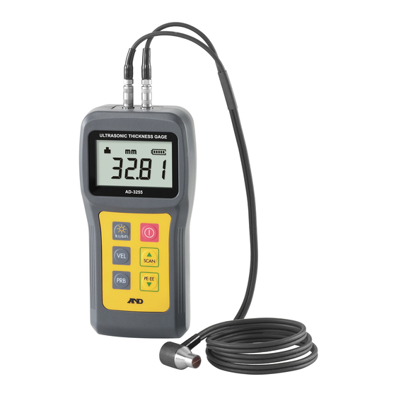
- Page 1 Ultrasonic Thickness Gage 1WMPD4003292A...
- Page 2 A&D Company, Limited. The contents of this manual and the specifications of the instrument covered by this manual are subject to change for improvement without any notice and obligation on the part of the manufacturer. 2017 All rights reserved.
-
Page 3: Table Of Contents
4-3-2. Calibration of Known Sound Velocities......17 4-3-3. Calibration of Unknown Sound Velocities......17 4-3-4. Two point calibration for Sound Velocities ......18 4-3-5. Initialization of Sound Velocities ........19 4-3-6. Pre-installed Sound Velocities..........20 Information and Cautions ............21 5-1. Battery..................21 5-2. Transducer ................21 5-3. -
Page 4: Safety Information
"Out of Order" on the AD-3255 and move it to place where it will not be used by mistake. Continued usage of it in this state is very dangerous. Contact your local dealer for repair. -
Page 5: Cautions Concerning Performance
Clean the connectors and electrical terminals using a dry lint free cloth. Operating temperature range : 0 [°C] to 50 [°C] Remove the batteries from the main unit when the AD-3255 is not used for a long time. - 3 -... -
Page 6: Introduction
Congratulations on purchasing an ultrasonic thickness gage AD-3255 of . We recommend that you read through this manual carefully before using the AD-3255 for the first time. Keep the manual nearby for reference. 2-1. Features The AD-3255 can measure the thickness of various materials using a principle similar to sonar, displays the thickness value in 0.1 [mm]... - Page 7 The AD-3255 is equipped with an automatic power-off function: When no operation is performed for approximately 5 minutes, the display blinks for 20 seconds and then the power is turned off. The AD-3255 can measure the thickness of other metal, plastic, ceramics, composite materials, epoxy resin, glass and a variety of other materials.
-
Page 8: Overview "Unpacking, Names, Operation & Response
3. Overview " Unpacking, Names, Operation & Response " 3-1. Unpacking Upon receiving the product, inspect the main unit and accessories contained in the package. Should anything be missing or damaged, contact and consult your local dealer. Use the carrying case for transport. -
Page 9: Names
Transducer connector "Transmitter" Transducer connector "Receiver" References Battery indicator Units Measurement mode Coupling state Display : Thickness data and settings are displayed. Switches : When pressed, the buzzer sounds. Strap holes Battery cover which covers the battery box in which two alkaline batteries, "LR6,... -
Page 10: Operation And Response
Decreases the parameter in the setting mode. Selects the measurement mode. Pulse - echo mode Hide + , Indication ....... This mode is for major measurements and can be used to detect a flaw or pit. Echo - echo mode Show +, Indication ....... - Page 11 - echo mode. The backlight consumes the battery power. The AD-3255 can not perform in other modes while the current mode is active or busy. For example : During sound velocity calibrations, the probe-zero function can not be performed.
- Page 12 Buzzer Different buzzer sound types indicate the following: ___ _ Turning on the AD-3255. pitt pitt Turning off the AD-3255. ___ __ _ _ Initializing sound velocity or when changing pitt pitt pitt pitt display resolution. Switch response pitt Measuring thickness.
-
Page 13: Measurements
Step 1. Install "or Replace" Batteries. Open the battery cover. Battery cover Install two new alkaline batteries LR6 or AA matching polarities "+ and -" with batteries those of the electrical terminals. Battery box Close the battery cover. Step 2. Connect Plugs of the Transducer. -
Page 14: Basic Measurement
Step 4. Calibrate the Zero Point. Contact the transducer to the surface of the test piece coated with couplant. Test piece The calibration is finished when the is displayed, 4.00 [mm] is indicator Couplant measured and the buzzer sounds "pitt". Result - 12 -... - Page 15 Step 5. Measure the Material. Contact the transducer to the surface of the material. The indicator Transducer displayed and the thickness is Material measured. Thickness Step 6. Turn off the Main Unit. Press the switch to turn off the main Version unit.
-
Page 16: Probe - Zero Function
Step 3. Calibrate the Zero Point. Contact the transducer to the surface of the Couplant test piece coated with couplant. The calibration is finished when the indicator is displayed, 4.00 [mm] is measured and the buzzer sounds "pitt". Test piece - 14 -... -
Page 17: Switching The Display Resolution
When the "blinking symbol " is displayed, and the contact of the transducer is lost for 2 seconds or more, the AD-3255 will display the smallest measurement data. The measurement value blinks 5 times when a minimum value is displayed. -
Page 18: Sound Velocity Calibration
Sample piece whose coating or paint has removed is required for both the single point and the two point calibrations. If the sample piece's coating or paint is not removed, a correct thickness value can not be displayed. -
Page 19: Calibration Of Known Sound Velocities
Step 1. Perform the Probe-Zero Function. Perform the "4-2-2. Probe - Zero Function". Step 2. Measure the Thickness of Sample Piece. Measure it and remove the transducer Apply couplant to the surface of the sample piece. Press the transducer against it. The thickness value is displayed. -
Page 20: Two Point Calibration For Sound Velocities
Perform the "4-2-2. Probe - Zero Function". Step 2. Measure the Thickness of the First Point. Apply couplant to the first point of the Measure it and remove the transducer sample piece. Press the transducer against it. The thickness value of the Couplant first point is displayed. -
Page 21: Initialization Of Sound Velocities
Thickness 4-3-5. Initialization of Sound Velocities Press the switch to turn on the main unit while pressing and holding the switch after turning off the main unit. Release the switch when the sound velocity is displayed. -
Page 22: Pre-Installed Sound Velocities
4-3-6. Pre-installed Sound Velocities The pre-installed sound velocities are as follows: Refer to the "5-6. Reference Data of Sound Velocities". The sound velocity vary in accordance with the temperature and characteristics of the substance. 5920 [m/s] Iron, Accessory test piece... -
Page 23: Information And Cautions
5-1. Battery Cautions Use the specified battery. Install and replace with new batteries. Install two new alkaline batteries matching polarities "+ and -" with those of the electrical terminals. Incorrect polarities may result in malfunctions or damage. Do not charge the battery. Do not short the terminals of the battery. Do not disassemble the battery. - Page 24 The surface whose thickness is to be measured should be clean and free of any small particulate matter, rust, or dirt. Make the measurement surface clean and free from particles, rust or dirt. If any of these obstructions are present, the transducer cannot make proper contact.
- Page 25 In this case, it is necessary to select the size of the transducer. Connect the transmitter plug and the receiver plug to the coaxial connectors on the main unit. The plugs can be connected to either the transmitter connector or receiver connector.
-
Page 26: Measurement Of The Tube & Pipe
"right angle" of the long axis direction. The measurement of narrow pipes uses two direction measurements. One of the directions is perpendicular to the long axis direction, and the other is parallel. The thickness is the smaller of the two values. - Page 27 Measuring Laminated Material In general, there is a difference in the density "sound velocity" between non-laminated and laminated materials "taping, covering or painted with epoxy, polyethylene and adhesive, etc.". Multi-laminated materials may even exhibit noticeable changes in the sound velocity across a single surface.
-
Page 28: Couplant
All materials do not allow sound waves to penetrate. Ultrasonic thickness measurement can be used for metal, plastic, glass and multifarious materials. but it can not use for a part kind of cast iron, concrete, wood, fiberglass "fibre-reinforced plastic"... -
Page 29: Measurement Principle
When the ultrasonic wave is transmitted from the transmitter element of the transducer, the ultrasonic wave pulse "T pulse" is inputted into the material, and the ultrasonic wave pulse "Echo B" is reflected at the bottom, and is received at the receiver element which is then amplified as an electric signal. -
Page 30: Reference Data Of Sound Velocities
5-6. Reference Data of Sound Velocities Caution The sound velocity of the substance varies in accordance with temperature and the characteristics of the substance. Sound velocity [m/s] Substance Water 20 [°C] 1480 1550 Natural rubber, Soft rubber 1900 Polyethylene 2170... -
Page 31: Specifications
1000 to 9999 m/s The range of the sound velocity ........0.65 to 600.0 mm Display range ................0.1 / 0.01 mm Display resolution ................The accuracy depends upon the measurement conditions and the surface of the material. - 29 -... - Page 32 Approximately 160 g "excluding batteries" Mass of the main unit ..Battery life Approx. 30 hours or more with backlight off, 25 °C and measuring 4 mm thickness continuously Battery indicator The battery indicator blinks when the battery power has been consumed.
- Page 33 List of the Transducer Accessory Type AD-3255-02 ..........Display symbol ..... Frequency 7 MHz ....... 6 mm Transducer element ..Range 0.8 to 200.0 mm (Steel) ........Cable Approximately 85 cm .......... Thin object, wall thickness of pipe, gradual ..........
Need help?
Do you have a question about the AD-3255 and is the answer not in the manual?
Questions and answers