Advertisement
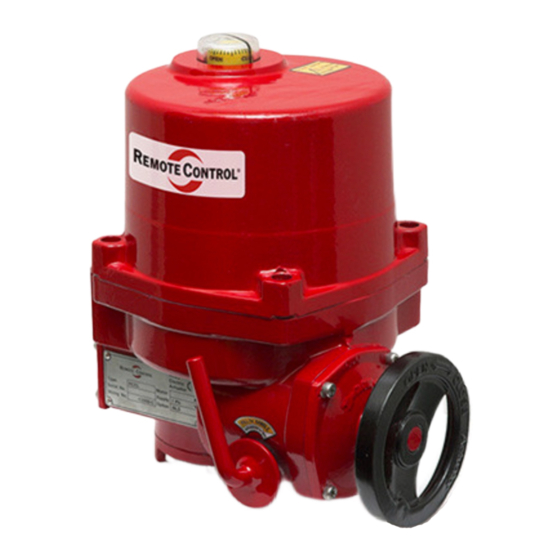
RCEL
Profi-Bus with LCU
CAUTION
ELECTRICAL SHOCK HAZARD.To avoid serious personal
injury, property damage, turn off ALL power to the actuator
before removing the cover.
Before installation, verify the nameplate information informa-
tion to insure the correct model number and voltage of the
actuator.
Be sure to completly review the actuator manual prior to
operation.
Final limit switch adjustment MUST be done after mounting
the actuator to the valve. Incorrect adjustment may cause
actuator failure.
Over torque switches are factory set. Tampering with the over
torque switch settings may damage the actuator and void the
warrenty.
To minimize the possible damage caused by condensation,
be sure to energize the heater.
Care should be taken when wiring 3 phase actuators.
Confirm proper rotation and limit switch shut-off function
during the initial operation. If the actuator rotates in the
reverse direction, then the phasing needs to be corrected
by switching two of the 3 phase wires on the terminal block.
CAUTION
Explosion-proof products must be used under the
temperature and environment appropriate for the product
spec.
Flameproof Enclosure Level and Enviroment of Actuator
Ex d IIB T4 -20°C ~ +55°C
Explosion proof actuators and wiring must be properly sealed
prior to operation. Improper installation may cause
a hazardous condition and failure of the explosion proof
enclosure. The manufacture is not responsible for any losses
or damages caused by incorrect installation.
www.rotork.com www.remotecontrol.se
Instruction
Standard Specification
Enclosure
Ambient
temperature
Main Power
Limit Switches
Torque Switches
Control Unit
Position Indicator
LED Lamp
Remote Dry
Contact
(Max 250VAC 5A)
Conduit Entry
Potentiometer
- 1 -
Top Quality Valve Actuators
Made in Sweden
Weatherproof enclosure IP67
Nema 4 and 6
Ex d IIB T4
-20 ºC to +55 ºC
1PH AC110 / 220V, 50 / 60 Hz
Open / Close Limit Switch
(Max 250VAC 15A)
Open / Close Torque Switch
(Max 250VAC 15A)
1. Non Intrusive Push Buttons
(Open / Stop / Close)
2. Non Intrusive Selector Switch
(Remote / OFF / Local)
Digital Display (0~100%)
Remote / Local / Fault
Open / Close
Full Open / Close
Fault Signal
Monitor (Remote / Local)
PF 3/4" x 2
Option: M20 Pitch 1,5 x 2,
NPT 3/4" x 2
0 ~ 1 kΩ
Advertisement
Table of Contents

Subscribe to Our Youtube Channel
Related Manuals for Remote Control RCEL Series


Summary of Contents for Remote Control RCEL Series
- Page 1 Top Quality Valve Actuators Made in Sweden RCEL Instruction Profi-Bus with LCU CAUTION ELECTRICAL SHOCK HAZARD.To avoid serious personal injury, property damage, turn off ALL power to the actuator before removing the cover. Before installation, verify the nameplate information informa- tion to insure the correct model number and voltage of the actuator.
- Page 2 Actuator Mounting Flange The (NA Series) mounting flange is manufactured to ISO5211 standards. If the actuator does not mount directly to the valve, then a mounting kit will need to be manufactured. Model Model RCEL006, RCEL009 RCEL015 ~ RCEL050 Model Model RCEL060 ~ RCEL100 RCEL150 ~ RCEL250...
- Page 3 Actuator Drive Bushing A removable blank drive bushing is suppled witch each actuator that can be machined to adapt to the valve stem. 1. Drive Bushing Separation 3. Drive Bushing Max Machine Bore Size Remove the 4 bolts by using an Allen key and the sepa- Model RCEL006 ~ RCEL100 rated drive bushing from actuator.
-
Page 4: Limit Switch Setting
Fig. 1 Manual Operation 1. Pull the lever located on the side of the actuator toward the hand wheel. The lever should “Lock” in position. Rotate the hand wheel and the actuator output will rotate. Fig. 1 2. If the lever does not “Lock” in the upright position, then turn the hand wheel halfway and pull lever to the right position. - Page 5 Marking Spec positions, and that the motor is not stalled or in an over- torque condition. Actuator Mode Display Remote: Actuator Remote Control Local: Actuator Local Control Off: Actuator Stopp Auto: Actuator Auto Scan Option: P.C.U...
-
Page 6: Push Button
Push Button Decision of the seating method in TQ CHECK Limit Position Local Mode Off Mode OPEN Open Command Manu Up Scroll TQ Check On Open, Close, Over Torque Local Mode Off Mode TQ Check Off Full Open / Close Limit 2 ~ 3 sec: Enter STOP Stop Command... -
Page 7: Setting Mode
Setting Mode ● Open & Close Press ● Marking Name Spec CLOSE OPEN Actuator Setting Actuator Position Position Display Manu Setting Mode Place the selector switch in “OFF” position and press the open and close button for over 2 seconds to enter the setting mode. - Page 8 STOP 2 sec STOP “TQ OFF” Setting 2 sec CLOSE STOP STOP 1 sec 2 sec 1 sec “TQ ON” Setting OPEN CLOSE 1 sec 1 sec STOP 2 sec Total Cycle STOP 1 sec OPEN CLOSE 1 sec 1 sec Actuator Position STOP 2 sec...
- Page 9 OPEN CLOSE STOP 1 sec OPEN 1 sec “TIME DELAY” 2 sec 1,5 sec Setting 1 sec STOP 2 sec CLOSE STOP STOP 1 sec 2 sec “TIME DELAY” 1 sec 0,5 sec Setting OPEN 1 sec The valve is adjustment between 0,5 sec and 5 sec in 0,5 sec increment.
-
Page 10: Self Diagnosis
Self Diagnosis Display Message Hove To Solve FAULT MOTOR OVERHEATING MOTOR TP ( 150°C TP Open ) 50 % Restart MOTOR TP FAULT FAULT VOID 50 % 50 % PH REV PH REV FAULT FAULT VOID 50 % 50 % PH LOSS PH LOSS FAULT... - Page 11 Profibus Data Format The profibus highway uses RS485, 2 wire communication. Up to 126 devices can be connected on a signal net- work provided suitable repeaters are included. Without repeaters only 32 devices, including the PLC are allowed. Address 126 is reserved for a new device appearing on the highway. PROFIBUS Master ACT 1...
- Page 12 ─Position operating (Index = 1) Bit Number Position Data Description 100% STOP OPEN CLOSE 2. Response Data (Master <─ Slave) : 3 bytes ─1st Data (Position) Position Data (0 - 255) Ex) Position Data 100: 100/2 → 50% ─2nd Data (Status) Bit Number Description Phase check (0:OFF, 1:ON) (Reserved)
- Page 13 Profibus Setting GSD FILE - MASTER: Program Install PROFIBUS - DP SOFTWARE SETTING 3) Master → Address Selector 1) Configuration Tool Operation 2) Master Select 4) MASTER SETTING FINISH www.rotork.com www.remotecontrol.se - 13 -...
- Page 14 5) Slave → Actuator Gsd File Add 8) DATA-EXCHANGE MODE 6) Address, Input Module, Output Module Setting 7) Configuration Attendance → On-line Operation www.rotork.com www.remotecontrol.se - 14 -...
- Page 15 Draw No. NU-2A4A-A www.rotork.com www.remotecontrol.se - 15 -...
- Page 16 Draw No. NS-2A4-A We reserve the right to make changes without notice www.rotork.com www.remotecontrol.se Ref No 654 / Art No 980654 ROTORK SWEDEN AB Box 80, Kontrollvägen 15, SE-791 22 Falun, Sweden Tel: +46 (0)23-587 00 • Fax: +46 (0)23-587 45 • falun.info@rotork.com - 16 -...
Need help?
Do you have a question about the RCEL Series and is the answer not in the manual?
Questions and answers