Advertisement
Quick Links
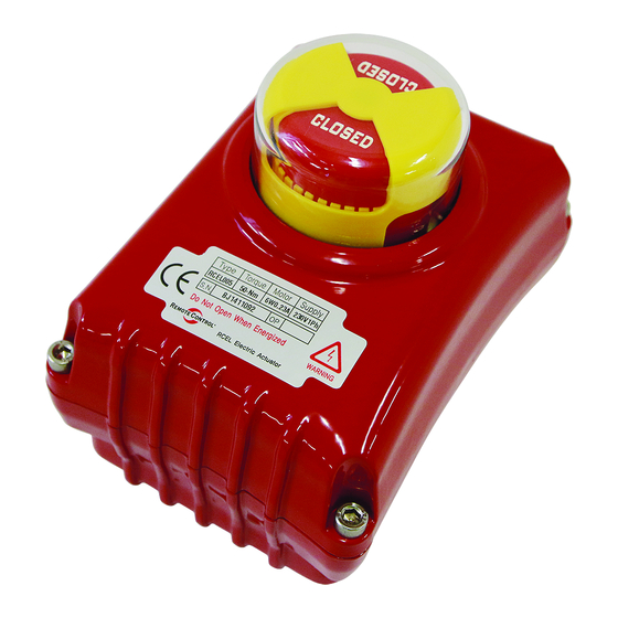
RCEL 005 / 005L
Electric Actuators
Installation
1. Mounting on valve A).
2. Electric wiring (B).
3. Adjusting (C).
4. Manual operation (D).
NOTE: Only electric wiring, according to
instruction B, is required when the actuator
is delivered from Remote Control mounted
on a valve. It is adjusted and ready for
operation.
WARNING!
Remove power before the cover
is dismantled! The actuator must be handled
with the utmost care when the cover is
removed and the power is connected.
A. Mounting on Valve
1. Operate the valve manually to fully open
or fully closed position before the actuator
is mounted.
2. Operate the actuator manually (see D) to
fully open or fully closed position.
3. Check that the actuator and valve stem
are in correct position. Please note, valve
and actuator must be in the same mode
(fully open / fully closed) prior to the
assembly.
4. Mount the actuator on the valve and
check that the actuator and valve stems
are centered and aligned. If a mounting
bracket is used, the fi t must be checked
so that no distortion or play exists.
5. Operate the valve manually with the aid of
allen key (see D) and check that the valve
moves with normal resistance.
6. Check that all screws are correctly
tightened.
Instruction
B. Electric Wiring
NOTE: Electric wiring must be carried out by
qualifi ed personnel only!
1. Loosen the screws on the cover and lift it off.
2. Check the voltage marked on the actuator
label.
3. Connect according to the enclosed wiring
diagram or, if the actuator is of standard
design, according to the wiring diagram
below. The wiring diagram is drawn in
unaffected position (the valve in intermediate
position).
4. Test run the actuator from the intermediate
position checking that the actuator turns in
the correct direction.
5. Test run the actuator and check that the limit
switches work correctly.
6. Check that the cable entries and possible
blind plug are sealed.
7. Mount the cover.
Wiring diagram No. ST 12000 A. Standard.
- 1 -
Top Quality Valve Actuators
Advertisement

Subscribe to Our Youtube Channel
Related Manuals for Remote Control RCEL 005


Summary of Contents for Remote Control RCEL 005
- Page 1 3. Connect according to the enclosed wiring instruction B, is required when the actuator diagram or, if the actuator is of standard is delivered from Remote Control mounted design, according to the wiring diagram on a valve. It is adjusted and ready for below.
- Page 2 C. Adjusting D. Manual Operation 1. Make the fi nal cam adjustments for the limit 1. Take the attached 6mm Allen key mounted switches (if necessary) according to instruc- underside the actuator. tion (a) below. 2. Insert the 6mm Allen key and turn the valve 2.
Need help?
Do you have a question about the RCEL 005 and is the answer not in the manual?
Questions and answers