Table of Contents
Advertisement
Quick Links
Digital Limit Controllers
E5GC-600 Factory Mutual Approved
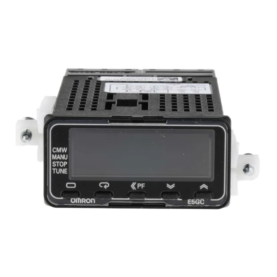
Large White PV Display That's Easier to Read.
Easy to Use, from Model Selection to Setup and Operation.
New Draw-out Jig allows the removal of the interior body
of the controller without changing the wiring.
Digital Limit Controller functions as a Limit Controller or a
temperature controller based on parameter setup.
What is a Temperature Limit Controller?
Factory Mutual and FM Global
FM Approvals
user s
1/32 DIN
48 × 24 mm
page 2
ured
e
.
1
1
Advertisement
Table of Contents

Related Manuals for Omron E5GC-600


Summary of Contents for Omron E5GC-600
- Page 1 Digital Limit Controllers E5GC-600 Factory Mutual Approved Large White PV Display That's Easier to Read. Easy to Use, from Model Selection to Setup and Operation. New Draw-out Jig allows the removal of the interior body of the controller without changing the wiring.
- Page 2 • Easy connections to a PLC with programless communications. E5GC- • Set up the Controller without wiring the power supply by Refer to your OMRON website for the most recent connecting to the computer with a Communications Conversion information on applicable safety standards.
-
Page 3: Model Number Legend
E5GC-600 Model Number Legend and Standard Models Model Number Legend E5GC- Control Number of Power Model Meaning Terminal Input Outputs 1 auxiliary supply Options type type and 2 outputs voltage E5GC 48 x 24 mm (1/32 DIN size) Control output 1... - Page 4 E54-CT3 Note: CX-Thermo version 4.62 or higher is required for the E5GC. For the system requirements for the CX-Thermo, refer to Mounting Adapter information on the EST2-2C-MV4 on the OMRON website (www.ia.omron.com). Model Y92F-53 (2pcs) Note: This Mounting Adapter is provided with the Digital Temperature...
-
Page 5: Specifications
E5GC-600 Specifications Ratings A in model number: 100 to 240 VAC, 50/60 Hz Power supply voltage D in model number: 24 VAC, 50/60 Hz; 24 VDC Operating voltage range 85% to 110% of rated supply voltage Power consumption 5.9 VA max. at 100 to 240 VAC, and 3.2 VA max. at 24 VAC or 1.8 W max. at 24 VDC... -
Page 6: Input Ranges
E5GC-600 Input Ranges ●Thermocouple/Platinum Resistance Thermometer (Universal inputs) Sensor Platinum resistance Infrared temperature Thermocouple type thermometer sensor Sensor 10 to 60 to 115 to 140 to specifica- Pt100 JPt100 PLII 70°C 120°C 165°C 260°C tion 2300 2300 1800 1800 1700... -
Page 7: Alarm Types
E5GC-600 Alarm Types Each alarm can be independently set to one of the following 17 alarm types. The default is 2: Upper limit. (See note.) Auxiliary outputs are allocated to alarms. ON delays and OFF delays (0 to 999 s) can also be specified. - Page 8 E5GC-600 *1 With set values 1, 4, and 5, the upper- and lower-limit values can *4 Set value: 5, Upper- and lower-limit with standby sequence be set independently for each alarm type, and are expressed as For Upper- and Lower-Limit Alarm Described Above at *2 “L”...
- Page 9 E5GC-600 Characteristics Thermocouple: (±0.3 % of indication value or ±1°C, whichever is greater) ±1 digit max.*1 Indication accuracy Platinum resistance thermometer: (±0.2 % of indication value or ±0.8°C, whichever is greater) ±1 digit max. (at the temperature of 23°C) Analog input: ±0.2% FS ±1 digit max.
-
Page 10: Communications Specifications
USB interface standard Conforms to USB Specification 2.0 Programless max. (Up to 16 for the FX Series) DTE speed 38,400 bps communica- Applicable PLCs: OMRON PLCs tions CS Series, CJ Series, or CP Series Computer: USB (Type A plug) Connector Mitsubishi Electric PLCs... -
Page 11: External Connections
E5GC-600 External Connections E5GC E5GC- (1) (2)(3)(4)(5) ↑ Terminal type Auxiliary/Limit Control Output Outputs 1, 2 The E5GC is set for a K-type thermocouple (input type = 5) by Relay output Relay outputs default. An input error (s.err) wil occur if the input type setting... -
Page 12: Wiring Methods
E5GC-600 Wiring Methods E5GC-@C E5GC-@6 Controllers with Screwless Clamp Terminal Blocks Controllers with Screw Terminal Blocks (M3 Screws) Controllers with Screwless Clamp Terminals Blocks Controllers with Screw Terminal Blocks • Wire stripping length: 8 to 12 mm • Terminal type: Forked or round crimped terminals •... - Page 13 E5GC-600 Dimensions (Unit: mm) Controllers E5GC-@6 Waterproof Packing (Accessory) Controllers with Screw Mounting Adapter (Accessory) Terminal Cover (Accessory) Terminal Blocks 63.6 44.8 40.8 • Use two Mounting Adapters, either on the top and bottom or on the right and left.
-
Page 14: Conversion Cable
E5GC-600 Accessories (Order Separately) ● USB-Serial Conversion Cable (2110) E58-CIFQ2 1510 LED (RD) USB connector (type A plug) Serial connector LED (PWR) LED (SD) ● Conversion Cable E58-CIFQ2-E Conversion Cable Connecting to the E58-CIFQ2 USB-Serial Conversion Cable (2110) (1510) 1510... -
Page 15: Operation
E5GC-600 Operation Setting Levels Diagram E5GC This diagram shows all of the setting levels. To move to the advanced function setting level and calibration level, you must enter passwords. Some parameters are not displayed depending on the protect level setting and the conditions of use. - Page 16 E5GC-600 Operation Parameters E5GC The following pages describe the parameters set in each level. Pressing the M (Mode) Key at the last parameter in each level returns to the top parameter in that level. Some parameters may not be displayed depending on the model and other settings.
-
Page 17: Monitor/Setting Item Level
E5GC-600 Monitor/Setting Item Level Monitor/Setting Monitor/Setting Monitor/Setting Monitor/Setting Monitor/Setting Item Display 4 Item Display 1 Item Display 3 Item Display 5 Item Display 2 Note: The monitor/setting items to be displayed is set in the Monitor/Setting Item 1 to 5 parameters (advanced function setting level). - Page 18 E5GC-600 Temperature High/Low Limit Controller This document is an addendum to the E5 C User’s Manual (H174-E1-xx). Please refer to this document for installation, specifications, wiring, etc. The purpose of this document is to show the programming steps to set the specified controllers up for FM temperature high limit monitoring.
- Page 19 E5GC-600 Selecting Upper/Lower Limit: The upper/lower limit selection setting enables switching between upper limit and lower limit operation. Resetting Limit Outputs: Depending on how the unit is configured the limit outputs can be reset by pressing the PF key for 1 second minimum or providing a switched input to an event input.
-
Page 20: Setting Procedure
E5GC-600 Appearance: Setting Procedure: Once the unit is powered up, Press and hold both the Level Key and the Mode key for three seconds. This will get the unit to Protect Level. 1. The first parameter is the Operation Level Protect/Adjustment Level Protect (oapt). Verify that this is set to 0. - Page 21 E5GC-600 Press and hold the Level key for three seconds. This will get the unit back to the Initial Setting level. 1. The first parameter in the initial setting level is the (in-t). This is the input type parameter use the instruction sheet or user manual to determine the correct setting based on the input type is applied to the unit for the application.
- Page 22 E5GC-600 At this time it is also recommended to verify that the set point upper and set point lower limits work correctly. Lower the set value by using the down arrow until the set point reaches the lower set point limit.
- Page 23 E5GC-600 Press and hold both the Level Key and the Mode key for three seconds. This will get the unit back to the Operation Level. Verify that none of the keys work on the unit other than the Up/Down arrows and the set point can be changed.
-
Page 24: Safety Precautions
E5GC-600 Safety Precautions Be sure to read the precautions for all E5GC-600 models in the website at: http://www.ia.omron.com/. Warning Indications Minor electric shock or fire may occasionally occur. Indicates a potentially hazardous Do not use any cables that are damaged. - Page 25 E5GC-600 Precautions for Safe Use • • • • • • • (E5GC) • • • •...
-
Page 26: Application Conditions
E5GC-600 Application Conditions Precautions for Correct Use Waterproofing Service Life Operating Precautions Measurement Accuracy Others... - Page 27 E5GC-600 Mounting Removing the Digital Temperature Controller from the case Mounting to a Panel E5GC E5GC...
-
Page 28: Precautions When Wiring
Three-year Guarantee Period of Guarantee Should the Unit malfunction during the guarantee period, OMRON The guarantee period of the Unit is three years starting from the date shall repair the Unit or replace any parts of the Unit at the expense of the Unit is shipped from the factory. -
Page 29: Terms And Conditions Of Sale
Buyer indemnifies Omron against all related costs or expenses. rights of another party. 10. Force Majeure. Omron shall not be liable for any delay or failure in delivery 16. Property; Confidentiality. Any intellectual property in the Products is the exclu-... - Page 30 OMRON ELETRÔNICA DO BRASIL LTDA • HEAD OFFICE São Paulo, SP, Brasil • 55.11.2101.6300 • www.omron.com.br OMRON EUROPE B.V. • Wegalaan 67-69, NL-2132 JD, Hoofddorp, The Netherlands. • +31 (0) 23 568 13 00 • www.industrial.omron.eu Authorized Distributor: Controllers & I/O •...
Need help?
Do you have a question about the E5GC-600 and is the answer not in the manual?
Questions and answers