Table of Contents
Advertisement
Quick Links
Brand:
Trinity
Type:
Multi-line Digital Display Panel Meter
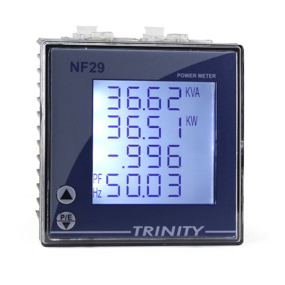
Models: Trinity NF29 Meters
CONNECTION DIAGRAM
On the rear panel, Trinity NF29 Meters has an RS-485 communication socket as shown in the following figure.
1. Please unscrew the RS485 terminal as shown in Figure T1.
2. Connect the cables to the RS485 bus terminal blocks.
3. Please make the connections from Terminal Block chip to TrackSo IoT
Gateway as mentioned in the Table – TT1.
DEFAULT CONFIGURATION IN TRACKSO IOT GATEWAY
Inverter ID: 1 (Range: 1 to 247)
Baud Rate: 9600
Data Bits: 8
Stop Bit: 1
Parity: N/A (None)
CONFIGURATION AT THE METER END
Enter into programming mode to setup meter for communication
In order to operate for all the field programmable parameters, it is easy user interface by pressing the keys such as
keys. Once the unit displays CT PRIMARY, press key to move into the next programmable parameter, UNIT
ADDRESS for RS485 communication.
TRACKSO INSTALLATION GUIDE FOR TRINITY NF29 METER
Figure T1 – Rear view of Trinity NF29 Meter
Trinity NF29 Pin No. &
Assignment
2
A
1
B
Table TT1 – Trinity NF29 Meter RS485 chip
connections with TrackSo IoT Gateway
TrackSo Pin No. &
Assignment
3
D+
4
D-
Advertisement
Table of Contents

Related Manuals for Trinity NF29


Summary of Contents for Trinity NF29
- Page 1 Multi-line Digital Display Panel Meter Models: Trinity NF29 Meters CONNECTION DIAGRAM On the rear panel, Trinity NF29 Meters has an RS-485 communication socket as shown in the following figure. Figure T1 – Rear view of Trinity NF29 Meter Trinity NF29 Pin No. &...
- Page 2 4) Now, the unit will reset and return into Run Mode. NOTE: The above details are mentioned in the Installation & Operation Manual for Trinity NF29 Meter. CONNECTING MULTIPLE METER...
- Page 3 TRACKSO WORKING 1. Insure correct connections as detailed in the installation guide. 2. Insert the SIM card. 3. Switch on the power to the TrackSo device. (Minimum 12V/1A input is required) 4. Power LED (Red) of TrackSo IoT gateway glows and stays ON. NOTE: TrackSo IoT Gateway will only be able to send data if the GPRS network is available at the installed location.
- Page 4 5. To check the exact network status send the following message to mobile number of the device SMS Command= *2222#<Stat.gsm> IMEI IMEI No. of the data logger (Device Key) Network SIGN Signal Strength out of 31 GPRS CONT- connected , NC- not connected Connected to TrackSo Server or not CONT- connected, NC- not connected no.
- Page 5 9. If the state remains Not receiveing for more than 10 minutes, click on your email ID at the top right of the screen and click on ‘Event Ingestion Logs’ in the dropdown. 10. Check if there is some log generated at the time of installation of the TrackSo IoT Gateway device. a.
Need help?
Do you have a question about the NF29 and is the answer not in the manual?
Questions and answers