Table of Contents
Advertisement
Quick Links
102 – Operational Manual
SLM
U
M
SER'S
ANUAL
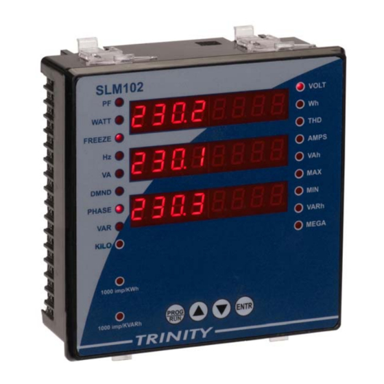
SLM102
0.2 Class Multifunction Power and Energy meter
This document contains the latest technical information about SLM102 which
is a micro-controller based 0.2 Class Multifunction Power and Energy meter.
The unit is tested against latest "MTE" Standard Model PRS400.3 having
basic accuracy of 0.02%, traceable upto International Standards derived using
appropriate ratio techniques.
The product, SLM102 is sophisticated electronic equipment, and the user is
advised to read this User's Manual carefully before attempting to install or
operate the equipment.
Published on:------
Document Version: 1.0
TRINITY
[1]
Advertisement
Table of Contents

Related Manuals for Trinity SLM102


Summary of Contents for Trinity SLM102
- Page 1 The unit is tested against latest "MTE" Standard Model PRS400.3 having basic accuracy of 0.02%, traceable upto International Standards derived using appropriate ratio techniques. The product, SLM102 is sophisticated electronic equipment, and the user is advised to read this User’s Manual carefully before attempting to install or operate the equipment.
- Page 2 Trinity Dealer or Factory. You are responsible for all costs (shipping, insurance, travel time) in getting the product to the service location.
-
Page 3: Table Of Contents
MODBUS RTU on RS485 Port ................47 Ethernet TCP/IP Communication ................ 48 SLM102 connected as Mini Web Server to a web browser......48 Data Logging and USB Port ................49 Installing the USB Software ................49 ... -
Page 4: Introduction
LAN/Internet. It has 2 MB of memory for data logging of all measured parameters, min-max values and events. SLM102 is a versatile meter, with all the features needed to implement a robust electrical load management system. It can be configured to suit most control and communication needs. - Page 5 Active Power min/max. - 3Φ & Σ system Apparent Power min/max. - 3Φ & Σ system Harmonic Measurement SLM102 measures the odd harmonics for 3Φ voltages and 3Φ currents upto 29th, including THDs for each waveform. Relay Outputs Options • Programmable relays for alarm or trip.
- Page 6 • Easy user interface through four push buttons switches. • Bright Red LED Display. Three rows of 8-digits each ensure unbroken display of even large energy register values • Two LEDs for Active and Reactive Energy (1000 impulse / KWh or KVARh) SLM102 TRINITY...
-
Page 7: Technical Specifications
√ Power (S) (0.01 Ib ≤ I < Imax) PF R-Phase √ Power 0.5 % for 0.5 < |PF| < 0.8, PF Y-Phase √ Factor (0.05 Ib < I < 1.2 Ib) PF B-Phase √ System PF √ √ TRINITY... - Page 8 (KVA) Demand : Sliding & Fixed Selectable Power Quality Mode Parameter 3P4W 3P3W Harmonics for Voltages(3 to 29 √ √ Harmonics for Currents(3 to 29 √ √ THD for each voltage √ √ THD for each current √ √ TRINITY...
- Page 9 Y-Phase √ B-Phase Min.-Max. System Active Power Minimum System Active Power ∑-P √ √ Min.-Max. System Apparent Power Minimum System Apparent Power ∑-Q √ √ Max. Demand Maximum Demand Value. √ √ Predictive Demand Fix-30 minutes Window √ √ TRINITY...
- Page 10 1A CT = 5A RMS Continuous Power Supply: Self Power. Unit has in-built 3 phase supply with an operating range of 50VAC - 480 VAC, 50-60 Hz. Output Specifications Programmable Relay Output Relay outputs Relay rating 3A @ 230 VAC, Resistive load. TRINITY [10]...
-
Page 11: Installation And Commissioning
102 – Operational Manual Installation and Commissioning The SLM102 supports two installation modes – 3P4W and 3P3W. The installation processes of these modes are described below: 3P4W Installation Mode Follow these steps to install / commission the unit. 1. Push the unit into the panel and mount using the clamps provided. The unit is not required auxiliary supply as unit has in-built 3 phases supply with an operating range of 50VAC - 480VAC, 50-60 Hz. - Page 12 102 – Operational Manual 7. Now, the unit needs to be programmed for the various parameters which are field programmable. For this refer to next section “OPERATIONAL DETAILS” 8. The unit is ready for operation. TRINITY [12]...
-
Page 13: 3P3W Installation Mode
CTs, above 0.4 % of rated CT. 6. Now, the unit needs to be programmed for the various parameters which are field programmable. For this refer to next section “OPERATIONAL DETAILS”. 7. The unit is ready for operation. TRINITY [13]... -
Page 14: Connection Scheme
102 – Operational Manual Connection Scheme TRINITY [14]... -
Page 15: Rs485 Connection
102 – Operational Manual RS485 Connection TRINITY [15]... -
Page 16: Operational Details
102 – Operational Manual Operational Details The load manager SLM102 is a versatile meter, with all the features needed to implement with a robust electrical load management system. It can be configured to suit most control and communication needs. The unit is achieved by making as many parameters field programmable, as much as possible. -
Page 17: Programming Mode
5A to 5000A. Date The date is RTC and can also be set with the format of date, month and year. i.e., DD/MM/YYYY format. To set CT Primary and Date, proceed the following instructions. TRINITY [17]... -
Page 18: Setting Pt Ratio And Time According To Rtc
The PT-Ratio should be set so as to give actual voltage for PT-operated meter. The PT Ratio is selectable from any one of the following: 1, 30, 60, 100, 200, 300 and 600. Time The Time is RTC and can also be set with the format of hh.mm.ss. TRINITY [18]... -
Page 19: Setting Log Duration, Demand Window And Unit Address
Setting Log Duration, Demand Window and Unit Address Log Duration For data logging, the Log Duration can be specified from 1 to 60 minutes. SLM102 has the capability to log data on its own Non-volatile RAM. This data is logged in an FIFO buffer. -
Page 20: Selecting Demand On, Installation Type And Ct-Secondary
CT-Secondary The CT Secondary can be selected to either 1 or 5 and the user should select the CT Secondary to give actual current value for CT operated meter. To set the above parameters, proceed the following instructions TRINITY [20]... -
Page 21: Setting Four Alarm Relays, Alarm On, Alarm Value And Alarm Hysteresis
USB Logger utility only. In case of Demand, the Delay is fixed with 2 seconds. This Delay programming is applicable only for USB utility. Refer last section, “Programming Mode Using USB Logger Utility”. If user is not desired USB programming utility, Alarm Delay will be 5 seconds by default only. TRINITY [21]... - Page 22 / nuisance operation of the relay near the Value. To set the Alarm Parameters, proceed the following instructions. 1. In the previous programmable parameter display, press key till the next display enters such as shown below. TRINITY [22]...
-
Page 23: Setting Four Events, Event On, Event Value And Event Hysteresis
Event On Same as “Alarm On”. Event Value Same as “Alarm Value”. Event Hysteresis Same as “Alarm Hysteresis”. 1. In the previous programmable parameter display, press key till the next display enters such as shown below. TRINITY [23]... -
Page 24: Selecting Baud Rate For Rs485 Port And Changing Password
Similay, Set for rest digits also. If any set digit is supposed to change again, press key several times to return onto the desired digit. Setting IP Address TRINITY [24]... -
Page 25: Setting Mac Address
Media Access Control sub layer of the Data-Link Layer of telecommunication protocols. Each byte can be set from 000 to 255. 1. In the previous programmable parameter display, press key till the next display enters such as shown below. TRINITY [25]... - Page 26 After setting all six bytes, press key to confirm that will return such as first display. 4. If the setting is completed press key for about four seconds to return into Run Mode. Otherwise, press key to enter into next programmable parameter. TRINITY [26]...
-
Page 27: Resetting Demand Manually / Daily/Monthly
’ starts blinking. Select the reset types by pressing key and then, press key to confirm the setting. 3. If the setting is completed, press key for about four seconds to return into Run Mode. Otherwise, press key to enter into next programmable parameter. TRINITY [27]... -
Page 28: Resetting Energy
1. In the previous programmable parameter, Reset Energy display, Select the Minimum( ) by pressing key such as same steps of Reset Energy where LED indicator will glow onto KW(WATT), HZ, KVA(VA), KVAR(VAR), VOLT, current(AMPS), Minimum(MIN) and Maximum(Max) such as shown below. TRINITY [28]... -
Page 29: Resetting Kw Demand And Kva Demand
Reset Energy where LED indicator will glow onto Demand (DMND) such as shown below. 2. Now, press key to confirm the setting. Simultaneously, the unit will also restart and return into Run Mode. TRINITY [29]... -
Page 30: Resetting Log
To reset Events Logging, proceed the following instructions. 1. In the previous programmable parameter, Reset Energy display, Select the DEMAND Demand( ) by pressing key such as same steps of Reset Energy where LED indicator will glow onto Demand (DMND) such as shown below. TRINITY [30]... -
Page 31: Resetting All Parameters
1. In the previous programmable parameter, Reset Energy display, Select the All ) by pressing key such as same steps of Reset Energy with the following display. 2. Now, press key to confirm the setting. Simultaneously, the unit will also restart and return into Run Mode. TRINITY [31]... -
Page 32: Run Mode
10.000 KWh and if value crosses 10000000 then it shows 1.000000 MWh. If the user has selected a PT-Ratio (PT-Primary/PT-Secondary)>1.0, voltages will auto scale to KV. SLM102 shows measured and calculated values on following different pages: Run Mode Displays The first page shows phase to neutral voltage in three phases. The LED indicator glows onto VOLT and PHASE which indicates that R-Phase, Y-Phase and B-Phase display in first row, second row and third row respectively. - Page 33 The third page shows Active Power (KW) in three phases. The LED indicator glows onto WATT and PHASE which indicates that R-Phase, Y-Phase and B-Phase display in first row, second row and third row respectively. TRINITY [33]...
- Page 34 3P3W. The fifth page shows Reactive Power (KVAR) in three phases. The LED indicator glows onto VAR and PHASE which indicates that R-Phase, Y-Phase and B-Phase display in first row, second row and third row respectively. TRINITY [34]...
- Page 35 The seventh page shows system powers. The LED indicator glows onto WATT, VA and VAR which indicates that Active Power (KW), Apparent Power (KVA) and Reactive Power (KVAR) display in first row, second row and third row respectively. TRINITY [35]...
- Page 36 The tenth page shows individual Voltage in three phases. The LED indicator glows onto VOLT which indicates that R-Phase, Y-Phase and B-Phase display in first row, second row and third row respectively. This page is not applicable for 3P3W. TRINITY [36]...
- Page 37 The twelfth page shows THD current in three phases. The LED indicator glows onto THD, AMPS and PHASE which indicate that THD current in R-Phase, Y-Phase and B-Phase display in first row, second row and third row respectively. The thirteenth page shows minimum voltage in three phases. The LED indicator TRINITY [37]...
- Page 38 The fifteenth page shows minimum Active Power in three phases. The LED indicator glows onto WATT, PHASE and MIN which indicate that minimum WATT in R-Phase, Y-Phase and B-Phase display in first row, second row and third row respectively. TRINITY [38]...
- Page 39 The seventeenth page shows minimum system of Active Power, Frequency (Hz) and Apparent Power. The LED indicator glows onto Active Power (WATT), Frequency (HZ) and Apparent Power (VA) which indicate that Active Power, Frequency and Apparent Power display in first row, second row and third row respectively. TRINITY [39]...
- Page 40 The nineteenth page shows minimum current in three phases. The LED indicator glows onto AMPS, MIN and PHASE which indicate that minimum Current in R- Phase, Y-Phase and B-Phase display in first row, second row and third row respectively. TRINITY [40]...
- Page 41 The twenty-first page shows maximum Active Power in three phases. The LED indicator glows onto WATT, PHASE and MAX which indicate that maximum Active Power in R-Phase, Y-Phase and B-Phase display in first row, second row and third row respectively. TRINITY [41]...
- Page 42 The twenty-third page shows maximum Active Power, Frequency, Apparent Power. The LED indicator glows onto Active Power (WATT), HZ, VA and MAX which indicate that maximum Active Power, Frequency and Apparent Power display in first row, second row and third row respectively. TRINITY [42]...
- Page 43 If the demand is calculated by the meter, based on sliding window technique, then unlike utility installed demand meters, this demand figure does not reset to zero at the end of the 30 minute integration window. If the user has initially selected KVA as demand parameter, the figure in the TRINITY [43]...
- Page 44 Last maximum Demand will hold as 400 KVA. The twenty-seventh page shows Predictive Demand. The LED indicator glows onto VA and DMND which shows Predictive Demand is for VA. If user selectable parameter is Watt (W), the LED indicator will glow onto WATT and DMND. TRINITY [44]...
- Page 45 2 stores 12 logs; event 3 stores 11 logs; and event 4 stores 16 logs. This event logging can be seen to the USB data downloading. The maximum Log is 16 for each event. Once the Log is overflow, the event will start logging from 1 and OVERFLOW will show YES. TRINITY [45]...
- Page 46 102 – Operational Manual The thirtieth page shows number of logs with RTC date and time. The maximum log for all the parameters is 23271 records. TRINITY [46]...
-
Page 47: Communications
In addition to the industry standard RS-485 communication port, several other communication options are also available in SLM102. These options make it possible for a user to select SLM102 to provide power and energy information into a variety of existing or new control systems and communication networks. Each communication option supports data transfer with external devices or applications. -
Page 48: Ethernet Tcp/Ip Communication
Ethernet TCP/IP Communication Ethernet-TCP/IP connection, Multiple sockets Ethernet connectivity enables the unit to respond to as many as 12 different requests. The SLM102 can act as a small web-server. This on-board web-sever, offers quick and easy access to basic measurement, without special software. Built-in web pages display a range of power, energy and basic power quality information through any web enabled device. -
Page 49: Data Logging And Usb Port
102 – Operational Manual Data Logging and USB Port SLM102 has a 2 MB non-volatile memory. This memory is used to store the minimum and maximum values of important parameters, events as defined by the user and the snapshot of the entire electrical system where all instantaneous and integrated parameters along with Harmonic data are saved. -
Page 50: Installation Of Usb Driver
Make sure that the USB cable is connected in between the PC and unit. If the USB connection is not all right, remove the USB cable and connect again. If the USB is connected for the first time, the wizard will show with following option. TRINITY [50]... - Page 51 Select the option, Yes, This time only and click Next to proceed for the next wizard such as shown below. The wizard will ask if your hardware comes with an installation CD or floppy disk, insert it now. Select the wizard option, Installation from a list or TRINITY [51]...
- Page 52 In the above dialog box, select option Search for the best drive in these location and click check box of Include this location in the search to specify path of usb drivers and then, click Next to get the path where the file is located. TRINITY [52]...
-
Page 53: Handling The Logger Window
Graph representation onto Logger window and Exporting the Logged data in to a excel sheet. Downloading the Logged data 1. By default the utility will show Logger 1.0 on desktop. Double-click on the Logger icon. Now the Logger will open with the following window. TRINITY [53]... -
Page 54: Exporting The Logged Data Including Min/Max Events And Harmonics Data
102 – Operational Manual 2. In the unit type list box, select the SLM102 and click OK and DOWNLOAD to start downloading the logged data with the following window. 3. In this LOG DATA window, click HARMONICS DATA at the bottom of the window to open the harmonics data window for all current and voltage. -
Page 55: Graph Representation
Auto scale, it is already selected by default. In case of Manual scale, select Manual scale. 3. To select for the parameters to be plotted, double-click in check box which will display the parameter selected at right list such as shown below. TRINITY [55]... - Page 56 Before plotting the parameters, the background color, axis color and label color should be specified by clicking as to represent along with the selected colors. 7. Now, click to plot a graph for the selected parameters such as shown below. TRINITY [56]...
-
Page 57: Programming Mode Using Usb Utility
Logger Utility. Using utility, user can easily specify for all the programmable parameters which is also more convenient than the programming in unit. Make sure USB cable coming from the PC is connected to SLM102 where the USB port is provided at the top of the unit. - Page 58 102 – Operational Manual Click down arrow and select SLM102(Prog) in list box that will open the page such as shown below. By default the cursor will blink in password box which shows user will enter password and click to enter into above Programming Mode. After configuring each programmable parameter, click respectively to confirm the settings.
-
Page 59: Control Outputs
102 – Operational Manual Control Outputs The relay contacts provided in SLM102 are rated for 3A @ 230VAC. They are also protected by snubbers against fast voltage transients which occur when inductive loads are switched off. Thus, the following points are to be taken care of when using these relay contacts: 1. -
Page 60: Slm102 As A Demand Management
1 minute (2 seconds in case of Demand). If all four relays are programmed to close on Demand and different values for closing and opening are set by the user, SLM102 can be used effectively as a Maximum Demand Controller with four relay contacts! -
Page 61: Appendix
102 – Operational Manual Appendix Address map of RS485 Port for various parameters of both 3P4W and 3P3W. RS‐485 MAP FOR SLM102 If PF is Lead Side then PF and Var Value are Negative. 1000 VOLT‐R 4 FLOAT ... - Page 62 4 FLOAT 1442 3rd Har. Amps‐B 4 FLOAT 1444 5th Har. Amps‐B 4 FLOAT 1446 7th Har. Amps‐B 4 FLOAT 1448 9th Har. Amps‐B 4 FLOAT 1450 11th Har. Amps‐B 4 FLOAT 1452 13th Har. Amps‐B 4 FLOAT 1454 15th Har. Amps‐B 4 FLOAT TRINITY [62]...
- Page 63 SECOND & MINUTE 2054 2 CHAR*2 HOUR & DUMMY 2055 2 CHAR*2 DATE & MONTH 2056 2 CHAR*2 YEAR & DUMMY 2057 2 0 2058 MAX DEMAND 4 FLOAT SECOND & MINUTE 2060 2 CHAR*2 TRINITY [63]...
- Page 64 YEAR & DUMMY 3041 0 3042 MAX VA‐R 4 FLOAT SECOND & MINUTE 3044 CHAR*2 HOUR & DUMMY 3045 CHAR*2 DATE & MONTH 3046 CHAR*2 YEAR & DUMMY 3047 0 96 TRINITY [64]...
- Page 65 3344 CHAR*2 HOUR & DUMMY 3345 CHAR*2 DATE & MONTH 3346 CHAR*2 YEAR & DUMMY 3347 0 96 3600 MIN VOLT‐B FLOAT 4 SECOND & MINUTE 3602 CHAR*2 2 TRINITY [65]...
- Page 66 YEAR & DUMMY 3641 0 3642 MAX VA‐B 4 FLOAT SECOND & MINUTE 3644 CHAR*2 HOUR & DUMMY 3645 CHAR*2 DATE & MONTH 3646 CHAR*2 YEAR & DUMMY 3647 0 96 TRINITY [66]...
- Page 67 Specifications/Literature/O & M Manual. Traceability: tested against "MTE" Standard Model PRS400.3 having basic accuracy of 0.02% traceable upto International Standards derived using appropriate ratio techniques. Result of Test : ………………………………………………………………… Remarks : ………………………………………………………………… Test engineer : ………………………………………………………………… Date : ………………………………………………………………… TRINITY [67]...
Need help?
Do you have a question about the SLM102 and is the answer not in the manual?
Questions and answers