Advertisement
Quick Links
Brand:
Sungrow
Type:
Solar On Grid String Inverter
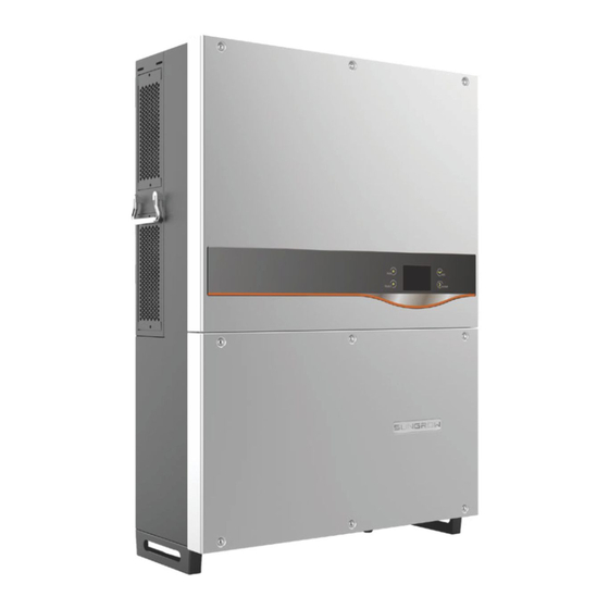
Models: SG33KTL-M SG40KTL-M SG49K5J SG50KTL-M SG60KU,SG60KU-M,SG60KTL,SG60KTL-M, SG36KTL-M SG8KTL-
M、SG10KTL-M、SG12KTL-M、SG80KTL、SG80KTL-M、SG80HV、SG125HV
CONNECTION DIAGRAM
The communication terminals (RS485) are located at the bottom of the inverter. And there are two connection
terminals on the configuration circuit board: RS485 A/B terminal blocks and RJ45 plug in terminals
Connection Steps
1. Loose the six screws on the lower connection cabinet
2. The communication terminals (RS485 A/B) are located at the bottom of the inverter as shown in Figure S1.
3. Connect the cables to the RS485 bus terminal blocks.
4. Please make the connections from the Terminal Block chip to TrackSo IoT Gateway as mentioned in the
Table – ST1.
Table ST1 – Sungrow RS485 chip connections with TrackSo IoT Gateway
TRACKSO INSTALLATION GUIDE FOR SUNGROW INVERTERS
Figure S1 – Sungrow Sring Inverter Connections
Inv Pin No. &
TrackSo Pin No.
Assignment
& Assignment
1
A
3
2
B
4
3
GND
4
A
Used for Daisy
5
B
Chain
6
GND
D+
D-
Advertisement

Related Manuals for Sungrow SG33KTL-M


Summary of Contents for Sungrow SG33KTL-M
- Page 1 4. Please make the connections from the Terminal Block chip to TrackSo IoT Gateway as mentioned in the Table – ST1. Inv Pin No. & TrackSo Pin No. Assignment & Assignment Used for Daisy Chain Table ST1 – Sungrow RS485 chip connections with TrackSo IoT Gateway...
-
Page 2: Setting The Baud Rate
DEFAULT CONFIGURATION IN TRACKSO IOT GATEW AY Inverter ID: 1, 2, 3, 4 …. Continuous numbering starting with 1, (Range: 1 to 247) Baud Rate: 9600 (Default) (Values: 9600, 19200, 38400) Data Bits: 8 , Stop Bit: 1 , Parity: None CONFIGURATION AT THE INVERTER END The admin password for entering the Install Settings is 091030. - Page 3 For a precise calculation of the statistics in the inverter itself and in a monitoring system, date and time have to be correct. Set the Correct Date & Time Communication Card Settings Single Inverter Multiple Inverters NOTE: The above details are mentioned in the Installation & Operation Manual for Sungrow Inverter-SG60KU on Page 99.
- Page 4 TRACKSO WORKING 1. Insure correct connections as detailed in the installation guide. 2. Insert the SIM card. 3. Switch on the power to the TrackSo device. (Minimum 12V/1A input is required) 4. Power LED (Red) of TrackSo IoT gateway glows and stays ON. NOTE: TrackSo IoT Gateway will only be able to send data if the GPRS network is available at the installed location.
- Page 5 5. To check the exact network status send the following message to mobile number of the device SMS Command= *2222#<Stat.gsm> IMEI IMEI No. of the data logger (Device Key) Network SIGN Signal Strength out of 31 GPRS CONT- connected , NC- not connected Connected to TrackSo Server or not CONT- connected, NC- not connected no.
- Page 6 9. If the state remains Not receiveing for more than 10 minutes, click on your email ID at the top right of the screen and click on ‘Event Ingestion Logs’ in the dropdown. 10. Check if there is some log generated at the time of installation of the TrackSo IoT Gateway device. a.