Advertisement
BT-A RF
GB
PRESENTATION
„RF" CONFIGURATION
PRESENTATION
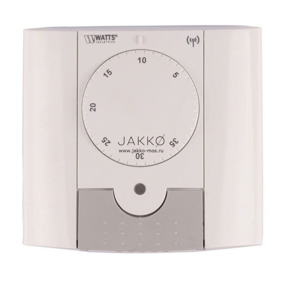
- Radio Frequency "RF" thermostat (433,92 Mhz)
specially designed for water floor heating managed by
actuators.
First of all, switch the button
- Radio Frequency "RF" thermostat
- Equipped with a switch to select 3 different operating
mode of the thermostat in OFF
(868 Mhz) specially designed to
modes:
position.
control different type of heating
systems.
Comfort
To learn (*) the RF thermostat
The setting temperature (adjusted on the knob) will
be followed all the time.
with the receiver you must put
Comfort
the receiver in "RF init" mode
The setting temperature (adjusted
Reduced
(please refer to the receiver
on the knob) will be followed all the
The reduced temperature will be followed all the time
leaflet).
time.
(setting temperature - 2°C)
OFF
Once, on the thermostat switch
OFF
Use this mode if you need to switch off the zone
the button mode on the comfort
Use this mode if you need to switch
managed by the thermostat.
off the zone managed by the
position.
thermostat.
LED Indicator.
- Now you can check the RF
distance, go to the room which
must be regulated. Put your
thermostat on the final position (On
Room
Select
the wall or table...), then put the
setting.
mode.
thermostat in Comfort mode
LED
(setting temperature position
Indicator.
Room
35°C). Close the door and go to the
setting.
receiver to check if the new status
Select
of the thermostat has received.
mode.
(The heating is generally showed
by a Red LED).
- Now return to the thermostat and
-
Batteries
switch off it. Check on the receiver
LED INDICATOR
again if it's also switched off (The
red LED must be turned off)
Red (Internal Sensor regulation)
TECHNICAL CHARACTERISTICS
Heating indication (few sec after
o
If the RF signals were
consign adjustment)
Measured temperature
received correctly, adjust
0.1°C
precision
your setting temperature as
Orange (External Sensor regulation)
Operating temperature
0°C - 50°C
you want.
Heating indication (During consign
Setting temperature
1 to 5 (with comfort
adjustment)
range
temperature on position 3)
If the RF signals weren't
o
Regulation
Proportional band 15min for
received correctly, check the
characteristics
2°K (PWM)
Green blinking
Installation (Receiver
Radio Frequency transmission.
Electrical Protection
Class II - IP30
position, distance...)
Power Supply
2 x 3V (CR2430)
Red Blinking
Battery operated life
~ 2 years
* To make the installation easier it
Low batteries indication. (Generally
will be better to have the
Radio frequency
433.92 MHz, <10mW.
visible after a RF transmission)
thermostat near to the receiver
EN 60730-1 : 2003
0.5 sec cycle => Internal sensor
during the configuration mode. (A
EN 61000-6-1 : 2002
failure
Norms and
EN 61000-6-3 : 2004
minimal distance of > 1meter must
1 sec cycle
=> External sensor
homologation:
EN 61000-4-2 : 2001
be respected)
failure
Your thermostat has been
EN300220-1/2
* When the batteries must be
designed in conformity
EN301489-1/3
replaced, always exchange the 2
with the following
standards or other
batteries in the same time.
normative documents:
R&TTE 1999/5/EC
Low voltage 2006/95/CE
EMC 2004/108/CE
Soft version
V 2.0x
TECHNICAL CHARACTERISTICS
Environmental:
0°C – 50°C
Operating temperature:
Shipping and storage temperature:
-10°C to +50°C
Electrical Protection
IP30 Class II
Setting temperature range
5°C to 35°C
Proportional Band
Regulation characteristics
(PWM 2°C for 10min cycle)
Power Supply
2 AAA LR03 1.5V Alkaline
Operating life
~2 years
Sensing elements:
Internal & External (option)
NTC 10k at 25°C
Radio Frequency
868 MHz, <10mW.
EN 60730-1 : 2003
EN 61000-6-1 : 2002
Norms and homologation:
EN 61000-6-3 : 2004
EN 61000-4-2 : 2001
Your thermostat has been
EN300220-1/2
designed in conformity with the
EN301489-1/3
following standards or other
R&TTE 1999/5/EC
normative documents:
Low voltage 2006/95/CE
EMC 2004/108/CE
BT-A RF
F
CONFIGURATION „RF"
PRESENTATION
o
Tout d'abord positionnez
- Thermostat Radio Fréquence (868
l'interrupteur de mode de votre
Mhz), spécialement conçu pour
thermostat sur la position OFF.
contrôler différentes installations de
chauffage
o
Ensuite (*), mettez votre
récepteur en mode "RF init".
Confort
(Reportez vous à la notice du
La température de consigne (ajustée
récepteur pour cette opération)
sur la mollette de réglage) sera
maintenue indéfiniment.
o
Sur le thermostat, basculez
l'interrupteur de mode sur la
OFF
position Confort
Utiliser ce mode si vous désirez
arrêter la zone gérée par votre
- Vous pouvez maintenant faire un
thermostat.
test de portée pour être sûr de
l'installation. Dans la pièce où doit se
trouver le thermostat, placez le à
l'endroit où il sera positionné plus
Température
tard (sur un meuble ou fixé au mur).
de confort
Réglez la consigne courante sur la
position Maxi (35°C), Fermez les
Voyant d'état
portes et allez vérifier la bonne
réception (le récepteur doit être en
Sélecteur de
chauffe Led Rouge à 1).
mode.
- Retournez au thermostat et
mettez-le maintenant en position
arrêt, vérifiez que le récepteur est
aussi passé en arrêt (Led rouge à
VOYANT d'ETAT
0)
o
Si la réception des signaux
Rouge (régulation sur sonde interne)
thermostat est correcte,
Indicateur de chauffe (quelques
ajustez votre température de
secondes après le réglage de la
confort comme vous le désirez
consigne)
o
Si la réception des signaux
Orange (Régulation sur sonde externe)
thermostats ne se fait pas
Indicateur de chauffe (en mode réglage
correctement, essayez de
de consigne uniquement)
rapprocher le thermostat du
récepteur, vérifiez l'installation
Vert clignotant
du récepteur (reportez vous à
Transmission de signal RF.
la partie Problèmes et solution)
Rouge Clignotant
* Pour une initialisation RF maîtrisée
Indication piles faible. (Généralement
il est préférable d'avoir le récepteur à
visible apes une transmission RF)
portée de vue lors de l'initialisation
Cycle de 0.5sec => défaut sur la sonde
(distance minimale > 1Mètre)
interne
Cycle de 1sec => défaut sur la sonde
externe
* Si les piles de votre thermostat ont
besoin d'être remplacées, changez
toujours les 2 piles en même temps.
CARACTERISTIQUES TECHNIQUES
Environnent. (Températures)
Fonctionnement:
0°C - 50°C
Transport et stockage :
-10°C à +50°C
Protection électrique
IP30 Class II
Plage de réglage de la
5°C à 35°C
température ambiante
Bande proportionnelle
Caractéristiques de régulations
2°C pour un cycle de 10min
Alimentation
2piles alkaline AAA LR03 1.5V
Autonomie
~2 ans
Elements optionnels:
Sonde interne ou externe
10k ohms à 25°C
Radio Fréquence
868 MHz, <10mW.
EN 60730-1 : 2003
EN 61000-6-1 : 2002
Normes et homologation:
EN 61000-6-3 : 2004
EN 61000-4-2 : 2001
Votre thermostat a été conçu pour
EN300220-1/2
répondre aux normes et directives
EN301489-1/3
européennes suivantes:
R&TTE 1999/5/EC
Basse tension 2006/95/CE
CEM 2004/108/CE
BT-A RF
DE
FUNK-KONFIGURATION
ALLGEMEINES
Betriebswahlschalter am
- BT Funk-Raumthermostat (868 MHz)
Thermostat auf OFF (AUS) stellen.
zur Einzelraumregelung, in
Verbindung mit BT Funk-
Anschließend (*) BT-Funk-
Regelverteilern.
Regelverteiler gemäß Anleitung in
Funk-Konfigurationsmodus bringen.
Komfortbetrieb / EIN
(Details siehe Anleitung BT-Funk-
Es wird permanent auf die (mittels
Regelverteiler).
Einstellknopf) eingestellte
Temperatur geregelt.
Betriebswahlschalter des
AUS
Thermostats auf Komfortbetrieb
Wählen Sie diese Betriebsart, um
stellen.
.
den vom Thermostat kontrollierten
Bereich abzuschalten.
- Sie können nun die Funkdistanz
prüfen, indem Sie in den Raum
gehen, dessen Temperatur reguliert
werden soll. Bringen Sie den
Thermostat in seine endgültige
Einstellung
Position (an der Wand oder auf einem
Solltemperatur
Tisch ...), und stellen Sie am
Thermostat die Betriebsart „Komfort"
LED
Leuchte
(Temperatur von 35°C) ein. Schließen
Sie die Tür, und überprüfen Sie am
EIN / AUS
Empfänger, ob dieser den neuen
Schalter
Status des Thermostats empfangen
hat (Der Heizvorgang wird in der
Regel durch eine rot leuchtende LED
angezeigt).
STATUS-ANZEIGE
- Gehen Sie nun wieder zum
Konstant Rot Heizbetrieb
Thermostat, und schalten Sie ihn aus.
Steuerung über internen Raumfühler
Überprüfen Sie wieder am
(für einige Sekunden nach Einstellung
Empfänger, ob dieser ebenfalls
Solltemperatur)
abgeschaltet hat. (Die rote LED muss
aus sein.)
Konstant Orange Heizbetrieb
o
Steuerung über externen Fühler
(für einige Sekunden nach Einstellung
Solltemperatur)
o
LED blinkt grün
Funkübertragung.
LED blinkt rot
Die Batterien sind schwach bzw. leer.
(Erscheint in der Regel im Anschluss
* Zur Erleichterung der Installation
an die Funkübertragung).
sollte sich der Thermostat, solange er
0,5 Sekunden Intervall => Störung des
im Konfigurationsmodus ist, beim BT-
internen Fühlers
Funk-Regelverteiler befinden. (Dabei
1 Sekunde Intervall => Störung des
ist ein Mindestabstand von ca.1 Meter
externen Fühlers
einzuhalten.)
* Bitte wechseln Sie bei einem
Batteriewechsel immer beide
Batterien.
TECHNISCHE DATEN
Umgebungsbedingungen:
Betriebstemperatur:
0°C - 50°C
Transport- und
-10°C bis +50°C
Lagertemperatur:
Schutzart
IP30 Class II
Einstellbereich
5°C bis 35°C
Raumtemperatur
Proportionalbereich (PWM
Regelverhalten
2 °C bei 10-min-Zyklus)
Stromversorgung
2 x AAA (Micro) 1.5V
Lebensdauer
~2 Jahre
Sensor-Elemente:
Intern und extern (Option)
NTC 10k Ohm bei 25°C
Funkfrequenz
868 MHz, <10mW.
EN 60730-1 : 2003
Normen und Zulassungen:
EN 61000-6-1 : 2002
EN 61000-6-3 : 2004
Ihr Thermostat wurde in
EN 61000-4-2 : 2001
Übereinstimmung mit den
EN300220-1/2
folgenden Normen oder anderen
EN301489-1/3
normativen Dokumenten
R&TTE 1999/5/EC
konzipiert:
Niederspannung 2006/95/CE
EMC 2004/108/CE
BT-A RF
RU
ОПИСАНИЕ
Комнатный
радиотермостат
MГц) серии ВТ предназначен для
температурного
регулирования
напольных системах отопления.
Комфортный режим / ВКЛ
Термостат поддерживает в посто-
янном режиме установленную (на
рукоятке) температуру в помеще-
нии.
Выключение / ОFF
При установке выключателя в
нижнее положение, термостат и
контроллируемые им контуры
отопления отключаются.
Ручка
установки
температуры
Светодиод
Выключатель
вкл. – выкл.
ПОКАЗАНИЯ СВЕТОДИОДА
Красный постоянный. Нагрев
Управление по встроенному датчику
(в течении нескольких секунд после
установки температуры).
Оранжевый постоянный. Нагрев
Wenn das Funksignal korrekt
Управление по внешнему датчику
empfangen wurde, legen Sie
(в течении нескольких секунд после
die gewünschte Solltemperatur
установки температуры).
fest.
Wenn das Funksignal nicht
Зеленый мигающий
korrekt empfangen wurden,
Передача радиосигнала
überprüfen Sie die Installation
(Position des Empfängers,
Красный мигающий
Distanz...)
Слабые или севшие батарейки (по-
является как правило после переда-
чи радиосигнала).
Интервал 0,5 секунды => сбой
встроенного датчика.
Интервал 1 секунда => сбой
встроенного датчика.
* Вегда заменяйте обе батарейки
одновременно.
ТЕХНИЧЕСКИЕ ДАННЫЕ
Температура окружающей
среды и рабочая температура:
Температура
транспортировки и хранения:
Защита:
Диапазон регулирования:
Тип регулирования
Питание
Срок работы
Температурные датчики:
Встроенный и внешний (опция)
Частота радиосигнала
Соответствие нормам
Ваш термостат разработан в со-
ответствии
со
следующими
стандартами и нормативны-ми
документами
РАДИОИНИЦИАЛИЗАЦИЯ
(установка связи с модулем)
(868
Выключите теромостат (нижнее
положение переключателя).
в
Перейдите в режим инициализа-
ции на коммутирующем модуле (*)
серии ВТ (см. инструкцию модуля).
Переведите термостат в комфор-
тный режим
.
- Проверьте качество приема моду-
лем радиосигнала. Для этого пере-
несите термостат на место предпо-
лагаемого монтажа (стена, стол) и
установите в комфортном режиме
температуру 35°C. Закройте дверь в
помещение и проверьте, получил ли
радиомодуль сигнал от термостата
(при получении трeбования нагрева
светодиоды зон, связанных с тер-
мостатом, горят красным цветом).
Выключите термостат. Проверьте
-
cнова радиомодуль (диоды соот-
ветствующих зон модуля должны
погаснуть).
o Если радиомуль получил сигнал,
то инициализация термостата бы-
ла проведена правильно. Устано-
вите на термостате комфортную
температуру.
o Если радиомодуль не принимает
корректно сигналы термостата, то
возможно он расположен вне ра-
диуса действия сигнала. Проверь-
те правильность подключения ан-
тенны, расстояния между радиo-
модулем и термостатом).
* В течении процесса инициализа-
ции термостат должен находиться в
непосредственной близости от ком-
мутирующего модуля (расстояние
ок. 1м).
* Термостаты серии ВТ совместимы
только с коммутирующими модуля-
ми серии ВТ.
ВНЕШНИЙ ДАТЧИК (опция)
Внешний датчик подключается к
выключенному
термостату.
При
включении
термостат
автомати-
чески распознает подключенный к
нему датчик (при подключении вне-
шнего датчика, управления осущес-
твляется только по нему).
0°C - 50°C
-10°C - +50°C
IP30 класс II
5°C - 35°C
ПИ регулирование
(PWM, 2 C цикл 10 минут)
2 x AAA батарейки (Micro) 1.5В
~2 года
NTC 10k Ом при 25°C
868 МГц, <10мВт.
EN 60730-1 : 2003
EN 61000-6-1 : 2002
EN 61000-6-3 : 2004
EN 61000-4-2 : 2001
EN300220-1/2
EN301489-1/3
R&TTE 1999/5/EC
EMC 2004/108/CE (электромагнитная
совместимость)
PPLIMP13664 Aa
Advertisement
Table of Contents

Subscribe to Our Youtube Channel
Related Manuals for Watts BT-A RF


Summary of Contents for Watts BT-A RF
- Page 1 BT-A RF BT-A RF BT-A RF BT-A RF PRESENTATION „RF“ CONFIGURATION CONFIGURATION „RF“ РАДИОИНИЦИАЛИЗАЦИЯ FUNK-KONFIGURATION ОПИСАНИЕ PRESENTATION PRESENTATION ALLGEMEINES - Radio Frequency “RF” thermostat (433,92 Mhz) (установка связи с модулем) Betriebswahlschalter am specially designed for water floor heating managed by Комнатный...
- Page 2 BT-A RF BT-A RF BT-A RF BT-A RF PRESENTATIE PRESENTATION PRESENTATION „RF“-CONFIGURATIE VŠEOBECNE RÁDIOVÁ KONFIGURÁCIA „RF“ KONFIGURATION „RÁDIÓFREKVENCIÁS PRODUCTOMSCHRIJVING BEMUTATÁS PRESENTATION - Radio Frequency “RF” thermostat (433,92 Mhz) - Radio Frequency “RF” thermostat (433,92 Mhz) - Radio Frequency “RF” thermostat (433,92 Mhz) KONFIGURÁLÁS...
- Page 3 Монтаж Installation Installation Installazione Instalación Installation Installáció – INSTALLATION – Installasjon instalação installatie Asennus Installation Inštalácia – – ~1,20M Min 20cm NTC 10k (25°C) 60mm 83mm 27mm PPLIMP13045 Bb...
- Page 4 Монтаж Installation Installation Installazione Instalación Installation Installáció – INSTALLATION – Installasjon instalação installatie Asennus Installation Inštalácia – – ~1,20M Min 20cm NTC 10k (25°C) 60mm 83mm 27mm PPLIMP13045 Bb...
Need help?
Do you have a question about the BT-A RF and is the answer not in the manual?
Questions and answers