Table of Contents
Advertisement
INTRODUCTION
Orthman's Vertical Fold Toolbars are the leading folding toolbars in the row crop industry. The innovative internal fold 4" x 24" cylinders can be set to fold
the toolbar to 90°, 115 °, 135°, or 180° making the Vertical Fold Toolbar the most versatile bar in agriculture. Vertical Fold Toolbars are factory set to fold to
the degree specified with the order. Vertical Fold Toolbars are available in size configurations up to 16 row 30". The strong construction, utilizing 3/8" wall
tubing (1/2" wall tubing center sections on models totaling more than 30' in total length), makes the Orthman Vertical Fold Toolbar a durable choice.
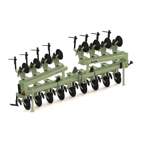
8315 Cultivator on Vertical Fold Toolbar
Category 3 or Category 4 three point hitches are available for Orthman Vertical Fold Toolbars and are available in multiple lengths and 3 different
hitch heights. Hinges are 14" wide and line-bored for smooth hinge movement and superior strength. All bars feature integrated bar stands, wing
rests (for toolbar foldings greater than 90°), safety lighting & decals.
This manual is considered to be an integral component of the Vertical Fold Toolbar and is designed to educate the owner and/or operator(s)
regarding safety, operation, maintenance, troubleshooting, and component identification. All personnel involved in the operation of this implement
are responsible for reading and understanding entire manual content. This manual is designed to keep the operator safe and knowledgeable as well
as prolong the life of the implement and maximize field efficiency. This manual should accompany the implement if it were ever to be sold.
We would like to thank you for placing your confidence in Orthman Mfg., Inc. Your Vertical Fold Toolbar is manufactured to meet the highest
standards and is built with precision and strength to increase your agricultural operation's dependability and profitability.
Thank you for choosing Orthman.
1 - 1
Advertisement
Table of Contents

Related Manuals for Orthman 8315 Cultivator


Summary of Contents for Orthman 8315 Cultivator
- Page 1 INTRODUCTION Orthman’s Vertical Fold Toolbars are the leading folding toolbars in the row crop industry. The innovative internal fold 4” x 24” cylinders can be set to fold the toolbar to 90°, 115 °, 135°, or 180° making the Vertical Fold Toolbar the most versatile bar in agriculture. Vertical Fold Toolbars are factory set to fold to the degree specified with the order.
- Page 2 5. Explain to the customer that the life expectancy of this machine depends on regular maintenance as directed in this manual. 6. Tell the customer to use the proper tools for service and make them aware of Orthman parts availability. 7. Write machine model number and serial number in the spaces provided below.
- Page 3 WARRANTY Orthman Mfg., Inc. warrants the whole goods products it manufactures to be free from defects in material or workmanship for a period of one (1) year from the date of sale of the product(s) to the original user. Products not manufactured, but supplied by Orthman Mfg., Inc. on Orthman products, are subject to, conform with, and are limited to the warranty of our suppliers.
-
Page 4: Table Of Contents
Practice Safe Maintenance - Prepare for Emergencies ........................2 - 8 Anhydrous Ammonia - Liquid Fertilizer Precautions - Safety Never Hurts ..................2 - 9 Safety Decals ....................................2 - 10 Orthman Decals and Orthman Serial Tag ............................2 - 14 PREPARATION AND SETUP Toolbar Component Identification ..............................3 - 1 Preparing the Vertical Fold Tillage Toolbar - Implement-to-Tractor Connection ................3 - 2... -
Page 5: Introduction
INTRODUCTION TABLE OF CONTENTS FIELD SETTINGS Field Operation ....................................4 - 1 Rigid Lock Pin & Wing Leveling Bolts..............................4 - 2 TROUBLESHOOTING Tractor will not hook-up to toolbar ..............................5 - 1 Toolbar will not fold or unfold .................................5 - 2 Toolbar will not fold or unfold .................................5 - 3 Removal of internal cylinder assembly ............................5 - 4 Removal of internal cylinder assembly ............................5 - 5 Notes .......................................5 - 6... -
Page 6: Farm Safety
Move to a safe place. Lightening, hail and tornadoes are unpredictable. Orthman Manufacturing, Inc. does not limit the potential effects or injuries nor prevention measures to those listed above. They are provided solely as a guideline to making your farm life safer. Always consult your Owner/Operators Manual for specific tool and equipment safety requirements. - Page 7 The Benefits of Improved Safety and Health Practices Orthman Manufacturing Provides this document in the hope that everyone that has a job to do, does it SAFELY. Our goal and yours should be to end each day in the best possible health. Better safety and health practices reduce fatalities, injuries, and illnesses as well as associated costs such as workers’...
- Page 8 Orthman dealer. EQUIPMENT SAFETY GUIDELINES Operator safety is the primary concern when designing an Orthman implement. Orthman integrates as many safety features into the implement as possible. You can avoid many hazards and possible accidents by observing precautions in this safety section.
- Page 9 SAFETY INFORMATION BE AWARE OF SIGNAL WORDS SIGNAL WORDS designate a degree or level of HAZARD seriousness. These signal words include: DANGER indicates a hazardous situation that, if not avoided, will result in death or DANGER serious injury. DANGER is limited to extreme situations, typically for machine compo- nents which for functional purposes, cannot be guarded.
- Page 10 Comply with state and local laws governing implement safety lighting. • A safety lighting package, conforming to implement lighting standard ANSI/ASAE S279.12, if not supplied with, is available for addition to your equipment. Contact your Orthman dealer for safety lighting package information. Refer to toolbar operator’s manual for safety lighting package installation and adjustment.
-
Page 11: Safe Operation - No Riders
SAFETY INFORMATION SAFE OPERATION READ AND UNDERSTAND THE ENTIRE CONTENT OF THIS CAUTION MANUAL BEFORE OPERATING OR SERVICING IMPLEMENT. Implement is to be operated by qualified personnel only. Never let children operate implement. A complete understanding of safety precautions, operation, and maintenance is mandatory before implement use. -
Page 12: Practice Safe Maintenance
SAFETY INFORMATION PRACTICE SAFE MAINTENANCE Proper maintenance is your responsibility. Maintenance neglect and/or poor maintenance WARNING practices can result in injury or death. Always use the proper tools to maintain implement. AVOID CRUSHING. Make sure all personnel are clear of the implement. Lower implement to the ground, place tractor in park, turn off engine, and remove key. - Page 13 SAFETY INFORMATION PRACTICE SAFE MAINTENANCE DANGER • Never operate a combustion engine in an enclosed area. Make sure there is adequate ventilation. Exhaust fumes can cause asphyxiation. • Service tires safely. Tire and rim separation can result in serious injury or death. Do not DANGER over inflate tires.
- Page 14 SAFETY INFORMATION ANHYDROUS AMMONIA - NH LIQUID FERTILIZER ANHYDROUS AMMONIA (NH ) AND LIQUID FERTILIZER APPEARS HARM- DANGER LESS. DIRECT EXPOSURE TO NH OR LIQUID FERTILIZER IS EXTREMELY DANGEROUS AND CAN RESULT IN INJURY AND/OR DEATH. • Keep a clean supply of water readily accessible in case of exposure to NH or liquid fertlizer.
-
Page 15: Safety Decals
ORANGE condition. Immediately replace damaged and/or missing decals. Replacement decals are CAUTION available from your Orthman dealer. To install decals: Thoroughly clean area where decal is to be placed and attach decal void of YELLOW bubbles. Refer to this safety information section for proper decal placement. - Page 16 SAFETY INFORMATION SAFETY DECALS FRONT OF HINGE 153-013.indd 1 6/16/2005 8:08:03 AM CYLINDER ADJUSTMENT COVER 2 - 11...
- Page 17 SAFETY INFORMATION SAFETY DECALS 153-172 Amber Retro-reflective FRONT OF TOOLBAR ON END OF WING AND HINGE 153-171 Orange Florescent 153-173 Red Retro-reflective REAR OF TOOLBAR ON END OF WING AND HINGE 2 - 12...
- Page 18 SAFETY INFORMATION SAFETY DECALS 153-171 Orange Florescent (rear-facing) 153-173 Red Retro-reflective INSIDE RED LIGHT BRACKET (rear-facing) 153-172 Amber Retro-reflective OUTSIDE AMBER LIGHT BRACKET 153-173 Red Retro-reflective SMV SIGN 2 - 13...
- Page 19 FRONT LEFT AND REAR RIGHT OF TOOLBAR ORTHMAN SERIAL TAG The Orthman serial tag contains valuable information. The model and serial numbers provide Orthman dealers and the Orthman Service Department with the exact specifications of your implement if any warranty or service issues need to be addressed.
-
Page 20: Preparation And Setup
10. RIGID WING LOCK PIN. Use this pin to lock down the toolbar to a rigid machine. When not in use, storage for these pins are at the end of the center section near the hinge pin. 11. TOOLBAR WING HINGE. Orthman’s own wing hinge design is built to allow the center section to couple with the wings while not giving up strength and versatility. - Page 21 If an Orthman row unit is used in conjunction with the Vertical Fold Tillage Toolbar, be sure to consult the row unit operator’s manual before attempting to operate the implement. Read and understand operator manuals for machinery used in conjunction with the Vertical Fold Tillage Toolbar.
-
Page 22: Shipping Configuration
PREPARATION AND SETUP SHIPPING CONFIGURATION The majority of the Vertical Fold Tillage Toolbar is assembled at Orthman Mfg., Inc. The Vertical Fold Tillage Toolbar is assembled in an appropriate ship- ping configuration to ensure transport safety and efficiency from the manufacturer. -
Page 23: Light Kit Component Identification
LIGHT KIT COMPONENT IDENTIFICATION An un-assembled light kit will come with your Vertical Fold Tillage Toolbar. The light kit will come in a box that has Orthman manufactured components in it, as well as an ag light kit from Wesbar or Cobo light companies. Orthman mounting and storage brackets will accommodate either brand, however cable and light components are not interchangable between the two brands. -
Page 24: Light And Light Bracket Assembly
PREPARATION AND SETUP LIGHT & LIGHT BRACKET ASSEMBLY Mount left and right light mounting brackets to light mount tabs located at the end of the center section (shown below). Use the provided 1/4” x 1” car- riage bolts and flange nuts to mount each bracket to the toolbar. Mount Amber (orange) colored lights to the bracket with the hardware provided in the light kit. -
Page 25: Light Cable Assembly
PREPARATION AND SETUP LIGHT CABLE ASSEMBLY Once lights are mounted, cables can be strung. Start in the center with the main wishbone harness. This cable will have one end that plugs into the front logic module harness, and 4 ends that will lead to the lights. On the Wesbar brand lights the ends with the heat shrink on the main wishbone harness will lead out to the amber lights. -
Page 26: Change Degree Of Fold
PREPARATION AND SETUP CHANGE DEGREE OF FOLD The primary feature of the Vertical Fold Toolbar is its ability to be folded to various degrees. 90° Vertical Fold Toolbars can be folded to either 90˚, 115˚, 135°, or 180˚. Modifica- 115° tions may need to be made to the current fold angle due to transportation, storage, and application issues of the particular operation. -
Page 27: Adjustable Wing Rest
PREPARATION AND SETUP ADJUSTABLE WING REST Vertical Fold Tillage Toolbars are standard with 180° fold configuration. If 115° or 135° fold configuration is desired, adjustable wing rests must be ordered separately (see adjustable wing rest parts page). The adjustable wing rests aid in relieving stress put on components of the internal hydraulic cylinder while the wings are folded. - Page 28 PREPARATION AND SETUP 90 DEGREE FOLDING PROCESS NOTE: THE 90 DEGREE FOLD TRANSPORT LOCK (SOLD SEPERATELY) IS MANDATORY FOR THE 90 DEGREE FOLD- ING POSITION. (SEE PARTS ID SECTION) NOTE: BE SURE TO FOLLOW ALL STEPS OF “TO CHANGE POSITION OF INTERNAL HYDRAULIC CYLINDER” BEFORE PROCEEDING.
-
Page 29: Notes
NOTES... - Page 30 FIELD SETTINGS FIELD OPERATION DANGER AVOID CRUSHING. Do not stand between tractor and implement when connecting or disconnect- ing implement. Injury or death can result from being trapped between the tractor and implement. AVOID CRUSHING. Make sure all personnel are clear of the implement. Lower implement to the ground, place tractor in park, turn off engine, and remove key.
- Page 31 FIELD SETTINGS FIELD OPERATION RIGID OPERATION. For Rigid operation in the field: With wings completely unfolded, move Rigid wing lock pin from Lock pin storage position and install into Rigid wing lock position. This will keep wing from floating up. NOTE: Toolbar will not be able to fold with wings locked down.
- Page 32 TROUBLESHOOTING AVOID CRUSHING. Make sure all personnel are clear of the implement. Lower implement to the DANGER ground, place tractor in park, turn off engine, and remove key. USE BAR STANDS TO SUPPORT THE IMPLEMENT. Park implement on a clean, dry, and level surface.
- Page 33 TROUBLESHOOTING AVOID CRUSHING. Make sure all personnel are clear of the implement. Lower implement to the DANGER ground, place tractor in park, turn off engine, and remove key. USE BAR STANDS TO SUPPORT THE IMPLEMENT. Park implement on a clean, dry, and level surface.
- Page 34 TROUBLESHOOTING AVOID CRUSHING. Make sure all personnel are clear of the implement. Lower implement to the DANGER ground, place tractor in park, turn off engine, and remove key. USE BAR STANDS TO SUPPORT THE IMPLEMENT. Park implement on a clean, dry, and level surface.
- Page 35 TROUBLESHOOTING AVOID CRUSHING. Make sure all personnel are clear of the implement. Lower implement to the DANGER ground, place tractor in park, turn off engine, and remove key. USE BAR STANDS TO SUPPORT THE IMPLEMENT. Park implement on a clean, dry, and level surface.
- Page 36 TROUBLESHOOTING AVOID CRUSHING. Make sure all personnel are clear of the implement. Lower implement to the DANGER ground, place tractor in park, turn off engine, and remove key. USE BAR STANDS TO SUPPORT THE IMPLEMENT. Park implement on a clean, dry, and level surface.
- Page 37 NOTES...
-
Page 38: Maintenance
MAINTENANCE PRACTICE SAFE MAINTENANCE Proper maintenance is your responsibility. Maintenance neglect and/or poor maintenance practices can result in injury or death. Always use the proper tools to maintain implement. AVOID CRUSHING. WARNING Make sure all personnel are clear of the implement. Lower implement to the ground, place tractor in park, turn off engine, and remove key. -
Page 39: Torque Specifications
MAINTENANCE TORQUE SPECIFICATIONS Unified Inch Bolt and Screw Torque Values SAE Grade 1 SAE Grade 2 SAE Grade 5, 5.1 or 5.2 SAE Grade 8 or 8.2 Bolt or Screw Lubricated Lubricated Lubricated Lubricated Size N•m lb-in N•m lb-in N•m lb-in N•m lb-in... -
Page 40: Lubrication
MAINTENANCE LUBRICATION GREASE • Grease - use high quality multi-purpose grease. • Follow recommended 50 hour service interval illustrated below. Internal fold Wing Hinge bushings 6 - 3... - Page 41 • Inspect all safety and Orthman decals and replace if missing or damaged. Contact your Orthman dealer for replacement decals. (pg. 2 - 10 thru 2 - 14) • Grease all zerks regardless of hourly interval prior to storage. (pg. 6 - 3) •...
-
Page 42: Parts Identification
PARTS IDENTIFICATION HITCH OPTIONS AND ASSEMBLY - CATEGORY 3/3N Part # Qty Notes Part # Qty Notes Description Description 302-592 Lower hitch tug pin 1 7/16” x 10 7/8” long 601-971* Med-lift hitch 5” x 7” 110” length 104-036 Lynch pin 7/16”... - Page 43 PARTS IDENTIFICATION HITCH OPTIONS AND ASSEMBLY - CATEGORY 4/4N Part # Description Qty Notes Part # Description Qty Notes 321-513 Lower hitch tug pin --------- 601-420* Med-lift hitch 5” x 7” 110” length 104-091 Roll pin 1/2” x 3” 601-421* Med-lift hitch 5”...
- Page 44 PARTS IDENTIFICATION HITCH CLAMP ASSEMBLY Part # Notes Part # Notes Description Description 601-360 Clamp assembly Heavy Duty - Med., **4” 601-380 Clamp assembly Regular Duty - Med., **4” 302-571 Clamp Top and Bottom 302-595 Clamp Top and Bottom 100-199 Bolt 3 or 4* 1”...
- Page 45 PARTS IDENTIFICATION INTERNAL FOLD ASSEMBLY -180 DEGREE Key Part # Description Qty Notes Key Part # Description Qty Notes 100-115 Bolt 1/2” x 1 1/4”, Grade 5 301-512 Friction plate 100-125 Bolt 1/2” x 4 1/4”, Grade 5 301-548 Linkage pin 102-007 Nut 1/2”...
- Page 46 PARTS IDENTIFICATION INTERNAL FOLD ASSEMBLY -16R30 Key Part # Description Qty Notes Key Part # Description Qty Notes 100-115 Bolt 1/2” x 1 1/4”, Grade 5 134-047 Bushing, split 1 3/4” x 1 1/2” x 5/8” 100-125 Bolt 1/2” x 4 1/4”, Grade 5 301-512 Friction plate 102-007 Nut...
-
Page 47: Toolbar Hinge Assembly
PARTS IDENTIFICATION TOOLBAR HINGE ASSEMBLY Part # Description Qty Notes Part # Description Qty Notes 301-146 Hinge pin 1 3/4” x 16 1/4” 110-001 Grease fitting 1/4” - 28, straight 104-005 Roll pin 1/2” x 2 1/2” 315-026 U-bolt 3/8”; 7” x 7” bar 134-005 Bushing 2.125”... -
Page 48: Hydraulic Cylinder Internal Components
PARTS IDENTIFICATION HYDRAULIC CYLINDER INTERNAL Part # Qty Notes Description 194-440 Seal kit for 194-499 cylinder 194-406 Cylinder rod 194-288 Gland 194-293 Piston 7 - 7... -
Page 49: Hydraulic Hose Assembly
PARTS IDENTIFICATION Internal Hoses HYDRAULIC HOSE ASSEMBLY Key Part # Description Qty Notes Part # Description Qty Notes 140-092 Hydraulic tip 3/4” O-ring - Pioneer 196-113 Hyd. hose - 96” 1/4” - 9/16 FJX x 9/16 FJX 196-563 Hyd hose - 60” 1/2”... - Page 50 PARTS IDENTIFICATION LIGHT MOUNTS AND SMV ASSEMBLY Part # Description Notes Part # Description Notes 153-109 SMV sign 108-018 Lock Washer 3/8” 102-085 Flanged lock nut 1/4” 100-575 Bolt 1/4” x 8” 106-077 Screw 1/2” x 1” 102-005 Hex Nut 3/8”...
-
Page 51: Light Kit Assembly - Wesbar
PARTS IDENTIFICATION LIGHT KIT ASSEMBLY - WESBAR Key Part # Description Qty Notes Part # Description Qty Notes 154-629 Harness - 84” 7 pin with logic module 152-055 cable ties 11 7/8” 154-630 Harness - 74” Main wishbone cable 152-023 cable ties 28”... -
Page 52: Light Kit Assembly - Cobo
PARTS IDENTIFICATION LIGHT KIT ASSEMBLY - COBO Key Part # Description Qty Notes Part # Description Qty Notes 154-829 Harness - 84” 7 pin with logic module 152-951 Light Red light (right) 154-830 Harness - 74” Main wishbone cable 152-705 lens Red lens 154-831 Cable - 13’... -
Page 53: Bar Stand Assembly
PARTS IDENTIFICATION BAR STAND ASSEMBLY Key Part # Description Qty Notes Part # Description Qty Notes 315-027 U - bolt 5/8”, 5”x 7” 104-065 Linch pin 5/16” x 1 11/16” 108-021 Lock washer 5/8” 303-744 Stand tube 48” 102-008 Nut 5/8”... -
Page 54: Adjustable/180°/170° Wing Rest Assembly
PARTS IDENTIFICATION ADJUSTABLE/180°/170° WING REST ASSEMBLY Key Part # Description Qty Notes Part # Description Qty Notes 100-154 Set Bolt 5/8”... - Page 55 NOTES...
Need help?
Do you have a question about the 8315 Cultivator and is the answer not in the manual?
Questions and answers