Sony VPL-VW10HT Service Manual
Hide thumbs
Also See for VPL-VW10HT:
- Operating instructions manual (124 pages) ,
- Dimensional drawing (1 page) ,
- Protocol manual (19 pages)

Related Manuals for Sony VPL-VW10HT


Summary of Contents for Sony VPL-VW10HT
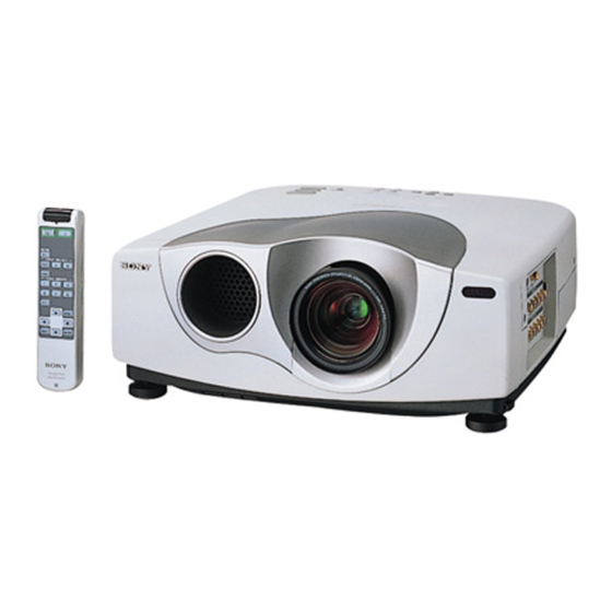
- Page 1 SERVICE MANUAL MODEL MODEL DEST. DEST........... VPL-VW10HT RM-PJVW10 WORLD WORLD LCD VIDEO PROJECTOR...
- Page 2 LES SCHÉMAS DE PRINCIPE, LES VUES EXPLOSÉES ET LES CRITICAL TO SAFE OPERATION. REPLACE THESE COMPO- LISTES DE PIECES SONT D’UNE IMPORTANCE CRITIQUE NENTS WITH SONY PARTS WHOSE PART NUMBERS APPEAR POUR LA SÉCURITÉ DU FONCTIONNEMENT. NE LES AS SHOWN IN THIS MANUAL OR IN SUPPLEMENTS PUB- REMPLACER QUE PAR DES COMPOSANTS SONY DONT LE LISHED BY SONY.
-
Page 3: Table Of Contents
3-3-2-4. SUB CONT, HUE and COLOR (15k RGB) Adjustment ..............3-2 3-3-3. ODD/EVEN Level Adjustment..........3-3 3-3-4. SAMPLE HOLD 2 Adjustment ..........3-3 3-3-5. RGB High Gain/Bias Adjustment ..........3-3 3-3-5-1. RGB High Gain/Bias Adjustment ........ 3-3 3-3-5-2. RGB W/B Low and Custom Adjustment ..... 3-4 VPL-VW10HT... - Page 4 B ........................ 7-3 C ........................ 7-4 TH ......................7-5 V ........................ 7-5 U ........................ 7-5 NF ......................7-6 NR ......................7-6 H ........................ 7-6 F ........................ 7-7 G ........................ 7-7 GA ......................7-7 8. Diagrams 8-1. Frame Schematic Diagram ................8-1 VPL-VW10HT...
- Page 5 Q ........................ 8-3 B ......................8-11 H ......................8-15 NF ......................8-17 NR ......................8-17 TH ......................8-17 U ......................8-17 V ......................8-17 C ......................8-18, 19 BM ......................8-30 F ......................8-32 G ......................8-32 GA ......................8-36 VPL-VW10HT...
-
Page 7: Operating Instructions
4-074-835-11(1) LCD Video Projector Operating Instructions Mode d’emploi Manual de instrucciones VPL-VW10HT © 1999 Sony Corporation... - Page 8 For the customers in Europe For the customers in Canada WARNING This product with the CE marking complies with both the This Class B digital apparatus complies with Canadian EMC Directive (89/336/EEC) and the Low Voltage Directive ICES-003. (73/23/EEC) issued by the Commission of the European To prevent fire or shock hazard, do not Community.
- Page 9 Table of Contents Overview Precautions ............... 7 (GB) Features ..............8 (GB) Location and Function of Controls ......9 (GB) Front/Left Side ............9 (GB) Rear/Right Side/Bottom ........... 9 (GB) Control panel ............11 (GB) Connector panel ............. 12 (GB) Remote Commander ..........
- Page 10 Precautions Maintenance On preventing internal heat build-up Precautions Maintenance ............34 (GB) After you turn off the power with the 1 key on the Replacing the Lamp ..........34 (GB) Remote Commander or the I / 1 key on the control On safety panel, do not disconnect the unit from the wall outlet Cleaning the Air Filter ...........
- Page 11 These from the Remote Commander. include DRC-MF (Digital Reality Creation 7 Connector panel Multifunction) (Sony’s proprietary high-quality Multi scan compatibility For details, see page 12 (GB). image technology); 3-D Gamma Correction, providing excellent uniformity; Cinema Black Mode, •...
- Page 12 Location and Function of Controls Location and Function of Controls Control panel 7 ENTER key Notes How to use the adjuster Enters the settings of items in the menu system. • Be careful not to let the projector down on your To adjust the height fingers.
- Page 13 VIDEO connector. output) jack S VIDEO: Selects the signal of equipment Connects to the control S out jacks of the Sony equipment. connected to the projector’s S VIDEO connector. Connects to the CONTROL S OUT jack on the supplied...
- Page 14 Distance (5.1) (7.8) (10.5) (13.2) (15.9) (19.9) (26.6) (40.0) When the Remote Commander causes malfunction, to video INPUT-A or INPUT-B in the SET SETTING menu to S video consult with qualified Sony personnel. We change the Maximum 1.8 14.1 output output according to the input signal.
- Page 15 Connecting Selecting the Menu Language Connecting with a Computer Select LANGUAGE with the M or m key, then When connecting with a computer Selecting the Menu Language press the , or ENTER key. This section describes how to connect the projector to a computer.
- Page 16 Projecting Projecting To correct the trapezoid Make setting or adjustment on an item. Press the INPUT key to select the input source. Projecting INPUT-A: Selects video signal input from the INPUT For details on setting individual items, see page 24 (GB). When the projecting image is a trapezoid, change the A connector, such as component projector’s position/height by moving the adjuster.
- Page 17 Using the MENU Projecting When the 16 : 9 picture is displayed on the To turn off the power To clear the menu display Using the MENU 4 : 3 screen Press the MENU key. Example: The 120 inch screen is used. To turn off the power from the control panel The projector is equipped with an on-screen menu for The menu display disappears automatically if no key...
- Page 18 The PICTURE CTRL Menu / The INPUT SETTING Menu The PICTURE CTRL Menu Input signals and adjustable/setting items The PICTURE CTRL Menu The INPUT SETTING Menu Adjusts color tones. The PICTURE CTRL (control) menu is used for The INPUT SETTING menu is used to adjust the Input signal The higher the setting, the picture becomes greenish.
- Page 19 The INPUT SETTING Menu The INPUT SETTING Menu NORMAL THROUGH: One-to-one mapping is Using the Control Panel SCAN CONV (Scan converter) SHIFT done on the picture with a normal ratio of 4:3. The Select a VIDEO MEMORY number (1 – 6) by Converts the signal to display the picture according to Adjusts the position of the picture input from the pressing the VIDEO MEMORY key.
- Page 20 VGA VESA 85 Hz 37.861 85.080 H-pos V-neg 832 saving mode if no signal is input for 10 minutes. LANGUAGE: ENGLISH 640 × 400 PC-9801 Normal 24.823 56.416 H-neg V-neg 848 Sony News 1708 POWER SAVING: OFF The power saving mode is canceled when a signal is VGA mode 2 31.469 70.086 H-neg V-pos 800...
- Page 21 Installation Examples The INSTALL SETTING Menu DIGIT KEYSTONE Installation Examples Corrects the trapezoid caused by the projection angle. Floor Installation If the base edge is longer, set a negative value; if the upper edge is longer, set a positive value to square the a: Distance between the screen and the center of the lens image.
- Page 22 Ceiling Installation Attaching the projector suspension support PSS-610 When installing the projector on the ceiling, use the For ceiling installation, consult with qualified Sony When installing the projector on the ceiling, use the Installation manual for Dealers of the PSS-610. The PSS-610 Projector Suspension Support.
- Page 23 Notes for Installation Notes for Installation Very dusty Blocking the ventilation holes Notes for Installation Unsuitable Installation Do not install the projector in the following situations. These installations may cause malfunction or damage Avoid installing the unit in a location where there is a to the projector.
- Page 24 Cleaning the Air Filter may scatter, causing injury. • If the air filter is excessively dirty, wash it with a • If the lamp breaks, consult with qualified Sony mild detergent solution and dry it in a shaded place. personnel.
- Page 25 The LAMP/COVER indicator The lamp has reached the end of its life. Replace the lamp (see page 34 (GB)). guide. If the problem still persists, consult with qualified Sony personnel. lights up. The lamp becomes a high temperature. Wait for 120 seconds to cool down the lamp and turn on the power again (see page 20 (GB)) .
- Page 26 Some of the items may not be available in some areas. For Projection system 3 LCD panels, 1 lens, projection (480 to 554 inches) CONTROL S IN/PLUG IN POWER details, please consult your nearest Sony office. system Stereo minijack 5Vp-p, plug in LCD panel 1.35-inch p-Si TFT LCD panel...
- Page 27 Specifications Specifications Dimensions Side Front 0 to 3 33.5 (0 to ) 136 (5 395 (15 167 (6 40 (1 80 (3 32.5 (15 319 (12 418 (16 334 (13 Bottom Center of the lens Center of the unit 89.5 73.5 112 (4 40 (1...
- Page 28 Specifications Index Index Index Lamp replacement 34 (GB) SCAN CONV (Scan converter) 25 (GB) LAMP TIMER 28 (GB) LANGUAGE 27 (GB) Screen size Location and function of controls 14 (GB), 29 (GB), 30 (GB), 38 (GB) Adjuster 10 (GB), 22 (GB) connector panel 12 (GB) SET SETTING menu 27 (GB) Adjusting...
-
Page 29: Service Informations
Section 2 Service Informations 2-1. Circuit Boards Location POWER BLOCK VPL-VW10HT... -
Page 30: Cabinet Assy Removal
4 Two screws (+B3 x 6) 5 Two screws (+B3 x 6) CN7001 2-3. Front Panel Assy Removal 3 Two screws (+B3 x 6) CN5008 4 Front panel assy 2 Lens cover (BT) 1 Two screws (+BVTP3 x 8) VPL-VW10HT... -
Page 31: G And Ga Boards Removal
3 Two screws 2 Holder(G) CN2001 (+BVTP3 x 8) 5 GA board CN2002 CN2009 CN2008 2-5. C Board Removal 1 Five screws (+B3 x 6) CN5006 CN5007 2 C board CN5010 C5803 CN5601 TP5801 CN5701 CN5801 Connector (CN4002) Connector (CN4004) VPL-VW10HT... -
Page 32: B And Q Boards Removal
3 B board Cover (9P receptacle) 2-7. Optical Unit Assy Removal • Remove the C Board (Refer to 2-5.). 2 Two screws (+PWH3 x 6) 3 Connector (2P) 1 Six screws (+PSW4 x 12) DC fan 4 Optical unit assy VPL-VW10HT... -
Page 33: Th, U, Bm And V Boards Removal
9 V board 2-9. Power Block Removal • Remove the optical unit assy (Refer to 2-7.). 1 Four screws (+B3 x 6) 2 Duct Connector (3P) 3 Three screws (+B3 x 6) 4 Power block Fin (VW) Holder (LPS) VPL-VW10HT... -
Page 34: Lens Assy Removal
7 Polarizer, B-OUT plate conductive section of the flexible cable in particular. !- Polarizer, B-IN 1 Four screws (+B3 x 8) plate 2 Lens bracket !' Polarizer, B-IN plate 3 Two screws (+B3 x 8) !] Polarizer, G-IN plate 8 Five screws VPL-VW10HT... -
Page 35: Note On Lamp Breakage
Then, the fly-eye lens may be cloudy at the lamp breakage, at that time wipe the suface of the lens with an authorized lens cleaner kit. . Cleaner (4-075-337-01) . Wiper (4-075-338-01) Note 2 Under the consideration of lamp’s reliability, set the lamp mode to “LOW” during repairing the unit with the cabinet opening and the lamp on. VPL-VW10HT... -
Page 37: Electrical Adjustments
4. Select the SAVE TO MEMORY on the Device adjust (B portion). page of the menu. Press the ENTER to save the data. <NTSC 100% Color Bars Signal> * Be sure to set the GND level to bottom with DC 0.5V range. VPL-VW10HT... -
Page 38: Sub Cont, Hue And Color (Component)
5. Select the item of 08 YUV CONT. Adjust the amplitude for 0.63 Vp-p. 6. Set the COLOR to 50. 7. Select the item of 09 YUV COL. Adjust the ← or → key so that the right and left bars are equal in level (A portion). VPL-VW10HT... -
Page 39: Odd/Even Level Adjustment
12. Repeat steps 10 and 11 several times. 11 SH/SH2R 13. Connect an oscilloscope to TP5702 on the C board. 13 SH/SH2B Perform the same adjustments as in steps 7 to 12 using R G GAIN/BIAS. 14. Connect an oscilloscope to TP5802 on the C board. VPL-VW10HT... -
Page 40: Rgb W/B Low And Custom Adjustment
8. Adjust the chromaticity (x, y) to the values shown below by the R GAIN and B GAIN of the W/B HIGH. 9. Repeat steps 5 to 8 until the chromaticity meets the below specifications. 10. Press the MEMORY key to save the data. VPL-VW10HT... -
Page 41: Adjustments In Replacement Of Prism And Optical Unit
“Factory reset” cannot be performed on device adjust LEVEL 1 menu items. (Implementing SAVE TO MEMORY will completely LEVEL 7 overwrite the data.) Do not change data unnecessarily. When adjusting a certain LEVEL, automatically the internal signal (flat field) of that level will be displayed. VPL-VW10HT... -
Page 43: Semiconductors
MAX202CSE-T HN1B01FU-TE85R MC74HC4538AF-T2 PC74HC123D-T SN74HCU04ANSR TC74VHC123F (EL) PQ20VZ1U MC100ELT20DR2 TC74LCX125FT (EL) TC74VHCT04AFT (EL) TC74VHC02FT (EL) 2SA1039A-QRSTA TLC2932IPW-E20 LETTER SIDE TLC2933IPW-E20 GS4981CTA NJM2533M (TE2) SN75157PS-ELL2000 TC7W00 (TE12R) S-80828ANNP-EDR-T2 S-80842ANNP-ED6-T2 MX0341B-F 2SB734-T-2 IMISM530AYB-D M62399FP-TE2 TC74VHCT541AFT TLC5733AIPM TC74VHC244F 2SB798-DL 2SB798-T1-DLDK (TOP VIEW) VPL-VW10HT... - Page 44 DAN202K-T-146 D10SC4M RD30FB1 UF4005PKG23 DAP202K-T-146 SEC1801C SEC2422C D6SB80 DA204K-T-146 MA111 RD27SB-T1 RD5.1SB-T1 RD9.1SB2-T1 UDZ-TE-17-3.9B D1NS4-TA D1NS4-TR2 RD12SB-T1 MA157-TX RD13ES-T1B2 1SS119-25TD RM11C D10LC20U RD15M-T1B1 VPL-VW10HT...
-
Page 45: Exploded Views
GUIDE (A), LED * 4-074-860-01 DUCT (KM) * 4-074-461-01 HOOD * 4-074-845-01 GUIDE (C), LED * 4-074-844-01 GUIDE (B), LED * 4-074-463-01 COVER (TP), LENS * 4-074-876-01 BUTTON, CONTROL 4-063-672-01 STOPPER (LCT) * A-1375-194-A H COMPL 1-500-082-11 CLAMP, SLEEVE FERRITE VPL-VW10HT... -
Page 46: Chassis
* 3-715-526-01 WASHER (M3) * A-1136-046-A B COMPL 4-066-202-01 SCREW, M3 * 4-073-788-01 SPRING, DOOR * A-1131-492-A BM MOUNT 1-900-222-47 CONNECTOR ASSY 2P * 4-073-787-01 DOOR, DUCT 3-701-822-01 HOLDER, WIRE * 4-074-866-01 WINDOW (RE), RE 1-500-082-11 CLAMP, SLEEVE FERRITE VPL-VW10HT... -
Page 47: Base
HOLDER, FILTER * 1-675-773-11 PWB, V 4-074-850-01 FILTER ! 1-468-445-21 POWER BLOCK 4-074-459-01 COVER, FILTER * 4-074-837-01 STAY (ADJ) * 3-715-526-01 WASHER (M3) * 4-074-859-01 ADJUSTER UNITE 4-073-989-01 SCREW (+B M3X12), PREVENTION 4-074-464-01 LAMP COVER * 1-543-830-11 CLAMP, SLEEVE FERRITE VPL-VW10HT... -
Page 48: Optical Unit
LENS B, RELAY 9-885-000-46 POLARIZER, G-OUT PLATE 9-885-000-41 LENS C, RELAY 9-885-000-48 POLARIZER, B-OUT PLATE 9-885-000-42 LENS D, RELAY 9-885-000-37 SPACER, COMPLETE 9-885-000-26 FLYEYE LENS B 9-885-000-24 PROJECTION LENS 9-885-000-27 FLYEYE/PS CONVERTER 9-885-000-44 LENS CAP 9-885-000-25 FLYEYE LENS A VPL-VW10HT... -
Page 49: Electrical Parts List
1-128-008-11 ELECT CHIP 3.3µF C3060 1-126-205-11 ELECT CHIP 47µF 6.3V C3013 1-117-681-11 ELECT CHIP 100µF C3061 1-164-004-11 CERAMIC CHIP 0.1µF C3062 1-128-004-11 ELECT CHIP 10µF C3014 1-164-004-11 CERAMIC CHIP 0.1µF C3063 1-126-205-11 ELECT CHIP 47µF 6.3V C3015 1-107-823-11 CERAMIC CHIP 0.47µF VPL-VW10HT... - Page 50 8-759-353-02 IC NJM2533M(TE2) C3136 1-164-004-11 CERAMIC CHIP 0.1µF IC3008 8-759-353-02 IC NJM2533M(TE2) C3137 1-117-681-11 ELECT CHIP 100µF IC3010 8-759-436-89 IC MC141627FT C3138 1-128-396-11 ELECT CHIP 470µF IC3011 8-759-269-92 IC SN74HCU04ANSR C3139 1-107-823-11 CERAMIC CHIP 0.47µF IC3012 8-759-568-27 IC MSM514265C-60JSDR1 VPL-VW10HT...
- Page 51 1-216-025-91 RES,CHIP 1/10W Q3031 8-729-026-49 TRANSISTOR 2SA1037AK-T146-R R3058 1-216-025-91 RES,CHIP 1/10W Q3032 8-729-120-28 TRANSISTOR 2SC1623-L5L6 R3059 1-216-025-91 RES,CHIP 1/10W Q3033 8-729-120-28 TRANSISTOR 2SC1623-L5L6 R3060 1-216-025-91 RES,CHIP 1/10W Q3034 8-729-026-49 TRANSISTOR 2SA1037AK-T146-R R3061 1-216-025-91 RES,CHIP 1/10W Q3035 8-729-026-49 TRANSISTOR 2SA1037AK-T146-R VPL-VW10HT...
- Page 52 1-216-295-91 SHORT R3130 1-216-017-91 RES,CHIP 1/10W * 4-374-846-01 COVER, CAPACITOR, CAP TYPE R3131 1-216-065-91 RES,CHIP 4.7K 1/10W R3132 1-216-017-91 RES,CHIP 1/10W R3134 1-216-651-11 METAL CHIP 0.50% 1/10W <CAPACITOR> R3135 1-216-057-00 RES,CHIP 2.2K 1/10W C2500 ! 1-113-912-11 CERAMIC 0.0047µF 20% 250V VPL-VW10HT...
- Page 53 1-164-004-11 CERAMIC CHIP 0.1µF C4103 1-107-823-11 CERAMIC CHIP 0.47µF C4026 1-164-004-11 CERAMIC CHIP 0.1µF C4104 1-107-823-11 CERAMIC CHIP 0.47µF C4027 1-117-681-11 ELECT CHIP 100µF C4105 1-107-823-11 CERAMIC CHIP 0.47µF C4106 1-164-004-11 CERAMIC CHIP 0.1µF C4028 1-164-004-11 CERAMIC CHIP 0.1µF VPL-VW10HT...
- Page 54 1-164-004-11 CERAMIC CHIP 0.1µF C4171 1-164-004-11 CERAMIC CHIP 0.1µF C4243 1-164-004-11 CERAMIC CHIP 0.1µF C4172 1-164-004-11 CERAMIC CHIP 0.1µF C4244 1-164-004-11 CERAMIC CHIP 0.1µF C4173 1-163-021-91 CERAMIC CHIP 0.01µF C4174 1-117-681-11 ELECT CHIP 100µF C4245 1-117-681-11 ELECT CHIP 100µF VPL-VW10HT...
- Page 55 8-719-914-42 DIODE DA204K D4011 8-719-037-53 DIODE RD27SB-T1 D4012 8-719-158-37 DIODE RD9.1SB2 <JACK> D4013 8-719-158-37 DIODE RD9.1SB2 D4014 8-719-158-37 DIODE RD9.1SB2 J4001 1-563-935-11 JACK, STEREO HEADPHONE D4015 8-719-800-76 DIODE 1SS226 (TRIGGER) J4002 1-563-935-11 JACK, STEREO HEADPHONE D4016 8-719-800-76 DIODE 1SS226 (CONTROLS-IN) VPL-VW10HT...
- Page 56 1-216-025-91 RES,CHIP 1/10W Q4005 8-729-120-28 TRANSISTOR 2SC1623-L5L6 R4018 1-216-049-91 RES,CHIP 1/10W R4019 1-216-295-91 SHORT Q4006 8-729-900-53 TRANSISTOR DTC114EK R4020 1-216-295-91 SHORT Q4007 8-729-026-49 TRANSISTOR 2SA1037AK-T146-R Q4008 8-729-900-53 TRANSISTOR DTC114EK R4021 1-216-025-91 RES,CHIP 1/10W Q4011 8-729-120-28 TRANSISTOR 2SC1623-L5L6 R4022 1-216-295-91 SHORT VPL-VW10HT...
- Page 57 1-216-017-91 RES,CHIP 1/10W R4098 1-216-624-11 METAL CHIP 0.50% 1/10W R4170 1-216-295-91 SHORT R4100 1-216-624-11 METAL CHIP 0.50% 1/10W R4171 1-216-041-00 RES,CHIP 1/10W R4101 1-216-025-91 RES,CHIP 1/10W R4173 1-216-017-91 RES,CHIP 1/10W R4103 1-216-624-11 METAL CHIP 0.50% 1/10W R4174 1-216-017-91 RES,CHIP 1/10W VPL-VW10HT...
- Page 58 R4307 1-216-645-11 METAL CHIP 0.50% 1/10W R4237 1-216-025-91 RES,CHIP 1/10W R4308 1-216-645-11 METAL CHIP 0.50% 1/10W R4238 1-216-025-91 RES,CHIP 1/10W R4309 1-216-645-11 METAL CHIP 0.50% 1/10W R4239 1-216-073-00 RES,CHIP 1/10W R4310 1-216-049-91 RES,CHIP 1/10W R4240 1-216-081-00 RES,CHIP 1/10W 6-10 VPL-VW10HT...
- Page 59 C2306 1-115-339-11 CERAMIC CHIP 0.1µF C2307 1-128-526-11 ELECT 100µF C2308 1-128-526-11 ELECT 100µF <RELAY> C2309 1-107-888-11 ELECT 47µF C2310 1-107-888-11 ELECT 47µF RY4001 1-755-384-21 RELAY C2311 1-107-888-11 ELECT 47µF RY4002 1-755-384-21 RELAY RY4003 1-755-384-21 RELAY RY4004 1-755-384-21 RELAY VPL-VW10HT 6-11...
- Page 60 Q2201 8-729-230-49 TRANSISTOR 2SC2712-YG Q2202 8-729-216-22 TRANSISTOR 2SA1162-G R2301 1-216-073-00 RES,CHIP 1/10W R2302 1-216-073-00 RES,CHIP 1/10W Q2203 8-729-230-49 TRANSISTOR 2SC2712-YG R2303 1-216-669-11 METAL CHIP 5.6K 0.50% 1/10W R2304 1-216-669-11 METAL CHIP 5.6K 0.50% 1/10W Q2204 8-729-216-22 TRANSISTOR 2SA1162-G 6-12 VPL-VW10HT...
- Page 61 C5015 1-162-970-11 CERAMIC CHIP 0.01µF C5016 1-124-778-00 ELECT CHIP 22µF 6.3V <COIL> C5017 1-124-778-00 ELECT CHIP 22µF 6.3V C5018 1-124-778-00 ELECT CHIP 22µF 6.3V L2601 1-406-659-11 INDUCTOR 10µH C5019 1-107-826-91 CERAMIC CHIP 0.1µF C5020 1-107-826-91 CERAMIC CHIP 0.1µF VPL-VW10HT 6-13...
- Page 62 1-107-826-91 CERAMIC CHIP 0.1µF C5261 1-107-826-91 CERAMIC CHIP 0.1µF C5149 1-107-826-91 CERAMIC CHIP 0.1µF C5262 1-107-826-91 CERAMIC CHIP 0.1µF C5150 1-162-970-11 CERAMIC CHIP 0.01µF C5301 1-107-826-91 CERAMIC CHIP 0.1µF C5151 1-107-826-91 CERAMIC CHIP 0.1µF C5302 1-107-826-91 CERAMIC CHIP 0.1µF 6-14 VPL-VW10HT...
- Page 63 1-117-681-11 ELECT CHIP 100µF C5630 1-107-826-91 CERAMIC CHIP 0.1µF C5535 1-117-681-11 ELECT CHIP 100µF C5631 1-107-826-91 CERAMIC CHIP 0.1µF C5537 1-162-970-11 CERAMIC CHIP 0.01µF C5632 1-107-826-91 CERAMIC CHIP 0.1µF C5538 1-162-970-11 CERAMIC CHIP 0.01µF C5633 1-107-826-91 CERAMIC CHIP 0.1µF VPL-VW10HT 6-15...
- Page 64 1-414-921-11 INDUCTOR CHIP 0µH C5828 1-162-970-11 CERAMIC CHIP 0.01µF FB5209 1-414-921-11 INDUCTOR CHIP 0µH C5829 1-164-156-11 CERAMIC CHIP 0.1µF FB5210 1-414-921-11 INDUCTOR CHIP 0µH C5830 1-107-826-91 CERAMIC CHIP 0.1µF C5831 1-107-826-91 CERAMIC CHIP 0.1µF FB5211 1-414-921-11 INDUCTOR CHIP 0µH 6-16 VPL-VW10HT...
- Page 65 8-759-460-72 IC BA033FP-E2 Q5301 8-729-230-49 TRANSISTOR 2SC2712-YG IC5310 8-759-490-41 IC TC74VHCT541AFT(EL) Q5302 8-729-026-49 TRANSISTOR 2SA1037AK-T146-R IC5311 8-759-195-81 IC TC7S86FU Q5303 8-729-230-49 TRANSISTOR 2SC2712-YG Q5304 8-729-230-49 TRANSISTOR 2SC2712-YG IC5401 8-759-482-47 IC M62399FP-TE2 IC5402 8-759-482-35 IC MC100ELT20DR2 Q5401 8-729-230-49 TRANSISTOR 2SC2712-YG VPL-VW10HT 6-17...
- Page 66 R5117 1-220-250-11 RES,CHIP 1/2W R5045 1-216-833-91 RES,CHIP 1/16W R5119 1-216-805-11 RES,CHIP 1/16W R5046 1-216-864-11 SHORT R5120 1-216-833-91 RES,CHIP 1/16W R5047 1-216-809-11 RES,CHIP 1/16W R5121 1-216-833-91 RES,CHIP 1/16W R5048 1-216-809-11 RES,CHIP 1/16W R5122 1-218-696-11 METAL CHIP 1.5K 0.50% 1/16W 6-18 VPL-VW10HT...
- Page 67 1-216-864-11 SHORT R5426 1-216-864-11 SHORT R5314 1-216-801-11 RES,CHIP 1/16W R5427 1-216-805-11 RES,CHIP 1/16W R5315 1-216-801-11 RES,CHIP 1/16W R5428 1-216-805-11 RES,CHIP 1/16W R5316 1-216-801-11 RES,CHIP 1/16W R5429 1-216-805-11 RES,CHIP 1/16W R5317 1-216-864-11 SHORT R5318 1-216-864-11 SHORT R5430 1-216-864-11 SHORT VPL-VW10HT 6-19...
- Page 68 1-216-057-00 RES,CHIP 2.2K 1/16W R5660 1-216-864-11 SHORT R5565 1-216-057-00 RES,CHIP 2.2K 1/16W R5661 1-216-864-11 SHORT R5566 1-216-817-11 RES,CHIP 1/16W R5662 1-216-864-11 SHORT R5568 1-216-057-00 RES,CHIP 2.2K 1/16W R5663 1-216-864-11 SHORT R5569 1-216-057-00 RES,CHIP 2.2K 1/16W R5664 1-216-864-11 SHORT 6-20 VPL-VW10HT...
- Page 69 R5754 1-216-812-11 RES,CHIP 1/16W R5847 1-216-825-11 RES,CHIP 2.2K 1/16W R5756 1-216-864-11 SHORT R5848 1-216-825-11 RES,CHIP 2.2K 1/16W R5757 1-216-864-11 SHORT R5849 1-216-789-11 RES,CHIP 1/16W R5758 1-216-864-11 SHORT R5850 1-216-789-11 RES,CHIP 1/16W R5759 1-216-864-11 SHORT R5851 1-216-812-11 RES,CHIP 1/16W VPL-VW10HT 6-21...
- Page 70 1-233-574-11 RES, CHIP NETWORK 10 RB5223 1-233-574-11 RES, CHIP NETWORK 10 RB5224 1-233-574-11 RES, CHIP NETWORK 10 RB5301 1-239-409-11 RES, CHIP NETWORK 47 ************************************************************* RB5302 1-239-409-11 RES, CHIP NETWORK 47 RB5303 1-239-409-11 RES, CHIP NETWORK 47 RB5305 1-239-409-11 RES, CHIP NETWORK 47 6-22 VPL-VW10HT...
- Page 71 1-216-037-00 RES,CHIP 1/10W R7035 1-216-037-00 RES,CHIP 1/10W D7021 8-719-914-44 DIODE DAP202K D7022 8-719-045-53 DIODE SEC1801C (V MEMO) R7036 1-216-037-00 RES,CHIP 1/10W D7023 8-719-914-43 DIODE DAN202K R7038 1-216-061-00 RES,CHIP 3.3K 1/10W R7039 1-216-061-00 RES,CHIP 3.3K 1/10W D7024 8-719-914-44 DIODE DAP202K VPL-VW10HT 6-23...
- Page 72 4-074-835-21 MANUAL, INSTRUCTION (GERMAN, ITALIAN) 4-074-850-01 FILTER 4-074-906-01 BOX, ACCESSORY ************************************************************* 9-885-000-82 BATTERY COVER (FOR RM-PJVW10) * 1-675-771-11 PWB, NR ********************** <CAPACITOR> C8100 1-124-589-11 ELECT 47µF <CONNECTOR> CN8100 * 1-564-518-11 PLUG, CONNECTOR 3P <IC> IC8100 8-749-011-03 IC GP1U26X 6-24 VPL-VW10HT...
-
Page 73: Block Diagrams
P.CONT FAN CONT1 FILTER COVER FAN CONT2 FILTER COVER LAMP COVER LAMP COVER SUB+5V SDA100K DC H1 S8300 S8200 LAMP ON SCL100K LAMP LAMP CONT LAMP PROT LAMP MODE SUB+5V T2601 Q2601 T2602 IC2602 REF REG CONV. OVERALL BLOCK VPL-VW10HT... - Page 74 -6.0V CONTROLS-IN CN1001 IC4016 +5V REG +6.0V IC4023(1/2) +12V COMPARATOR +5V-4 IC4015 +3.3V REG -6.0V D4003 J4001 COMP SUB+5V +4.5V TRIGGER +3.3V REF V PREVENT IC4028 +3.3V REG +3.3V-2 INPUT TERMINAL,3CH 8BIT A/D CONVERTER DRC,RGB INTERFACE,Y/C/V SW Q BLOCK VPL-VW10HT...
- Page 75 CN1006 UCAS MCAS +6.0V Q3023 LCAS MRAS FSCO 47 BUFF IC3011 +4.5V +4.5V FSCI TO G BOARD CN2004 CN1007 CN1010 FAN4 FAN4 +B FAN4 GND +17.0V +6.0V TO G BOARD -6.0V CN2003 (COLOR DECODER,3LINE/3D COMB,A/D CONVERTER) B, BM BLOCK VPL-VW10HT...
- Page 76 IC5104 +5V REG CNT1B CNT1 95 RESET CNT1A IC5122 +14.5V REG +17V TO Q BOARD +14.5V CN4002 +15.5V IC5106 +15.5V REG IC5109 +12V REG +12V IC5107 +3.3V REG SUB+5V SUB +3.3V POWER PROT IC5309 +3.3V REG +4.5V +3.3V-5 IC5034,VDD VPL-VW10HT...
- Page 77 RESET MCLKX SIGCEN LCD-RGT 1 OUT R PROCESS CNT1,CNT2 B-VCOM LCD-HST HCK1B HCK1 HCK1R,2R,1G,2G,1B,2B HCK2B HCH2 LCD-ENB HSDA,HSCL LCD-VCK SDA100K,SCL100K LCD-VST PW OSD ENA LCD-DWN LCD-PST COMR VCOM SIGCEN,R/G/B-VCOM HSDA,HSCL SDALOOK,SCLLOOK PW OSD ENA C, TH, U, V BLOCK VPL-VW10HT...
- Page 78 (REARSIRCS RECEIVE) CN5009 LAMP LED TO C BOARD TEMP LED IC8100 CN5007 SIRCS CN8100 POWER LED SIRCS-NR P.SAVE LED D7015 ON/STBY Q7001-7003 D7002,7003,7005 Q7005-7007 D7007,7008,7010 LIGHT ON D7001 D7012-7014 D7025 D7022 D7026 D7027-7034 H/NF/NR BLOCK H, NF, NR BLOCK VPL-VW10HT...
- Page 79 REF 8 TO BM BOARD CN1006 Q2202-2204 P CONT CN2007 SUB+5V T2601 (SUB+5V REG) CN2011 D2601 CN2012 D2602 SUB+5V Q2601 Q2602 Q2603-2605 SWITCHING IC2603 +5V DET CONV SHUNT REG REF 8 T2602 IC2602 V REF F, G, GA BLOCK VPL-VW10HT...
-
Page 81: Diagrams
HCK2 SUB +5V SUB +5V CN5007 CN8100 SIRCS-NF SIRCS-NF COML WHT-L S-MICRO C-S(15K) C-S(15K) CN3001 CN1005 B-TO-B B-TO-B (REAR SIRCS RECEIVE) CR(15K) CR(15K) CB(15K) CB(15K) YG(15K) YG(15K) VVDD SOUT C(S) C(S) VCOM Y(S) Y(S) C-VIDEO C-VIDEO N.C. N.C. B-SS1701<08.>-KESSEN VPL-VW10HT... - Page 82 ∗ L-4 IC4025 Q4053 ∗ M-4 ∗ E-5 : METALIZED POLYPROPYLENE IC4026 Q4060 IC4027 : BIPOLAR ∗ M-1 IC4028 *:B Side mount : HIGH TEMPERATURE IC4029 IC4029 : HIGH RIPPLE IC4030 IC4031 IC4032 IC4033 IC4034 IC4035 IC4036 IC4038 IC4039 VPL-VW10HT...
- Page 83 – B SIDE – SUFFIX ; -11 – A SIDE – SUFFIX ; -11 VPL-VW10HT...
- Page 84 OµH Q4003 R4005 :AL-CP Q4004 DTC144EKA B:CHIP 470k DTC144EKA :CHIP D4005 INVERTER INVERTER DAP202K PROTECT J4002 JL4012 (DC+5V) CONTROLS-IN JL4013 C4005 D4002 L4003 470p RD9.1SB2-T1 OµH JL4014 CH:CHIP Q(1/6) CLAMP INPUT TERMINAL,TIMER,3CH 8BIT A/D CONVERTER, DRC,RGB INTERFACE,Y/C/V SW. B-SS1701<08.>-Q..-P1 VPL-VW10HT...
- Page 85 :CHIP :RN-CP R4078 B:CHIP DAC2 SAD1 4.7k R4077 :CHIP DAC1 SAD0 :CHIP DAC0 50/60 FROM 4/6 FROM 6/6 15KRY/OTHER 2101/OTHER TO 5/6 R4085 CV/OTHER Q(2/6) :CHIP TO 6/6 YC/OTHER 15KRGB/OTHER INPUT TERMINAL,TIMER,3CH 8BIT A/D CONVERTER, DRC,RGB INTERFACE,Y/C/V SW. B-SS1701<08.>-Q..-P2 VPL-VW10HT...
- Page 86 10MHz 2SA1037AK R4204 2.2k BUFFER :RN-CP Q4028 2SA1037AK BUFFER R4200 R4209 R4206 :CHIP :CHIP RC-U :RN-CP Q4025 Q4029 2SA1037AK 2SA1037AK BUFFER BUFFER FL4002 R4205 10MHz 2.2k R4213 :RN-CP Q(3/6) :CHIP INPUT TERMINAL,TIMER,3CH 8BIT A/D CONVERTER, DRC,RGB INTERFACE,Y/C/V SW. B-SS1701<08.>-Q..-P3 VPL-VW10HT...
- Page 87 C4204 B:CHIP R4236 :CHIP R4288 2SA1037AK :RN-CP :RN-CP :RN-CP 470k 3.3k VCO LIM :CHIP 6.3V C4205 R4286 :CHIP R4247 :CHIP :AL-CP 2.2k 3.3k :CHIP :CHIP B:CHIP Q(4/6) FROM 3/6 RCYUV INPUT TERMINAL,TIMER,3CH 8BIT A/D CONVERTER, DRC,RGB INTERFACE,Y/C/V SW. B-SS1701<08.>-Q..-P4 VPL-VW10HT...
- Page 88 2.2k B:CHIP VS INV R4138 :CHIP IC4014 TC7W14F R4108 :CHIP 4.7k :RN-CP C4070 100p R4126 CH:CHIP :CHIP R4146 47 :CHIP R4148 10k :CHIP C4283 D4034 0.001 Q(5/6) DAN202K B:CHIP PROTECT INPUT TERMINAL,TIMER,3CH 8BIT A/D CONVERTER, DRC,RGB INTERFACE,Y/C/V SW. B-SS1701<08.>-Q..-P5 VPL-VW10HT...
- Page 89 TO 4/6 VD(RC) A/D CONVERTER, 15KRY/OTHER ≠≠≠≠≠ ≠≠≠≠ TO 2/6 FROM 2/6 DRC,RGB INTERFACE, TO 4/6 PAL/NTSC Y/C/V SW. JL4055 B-SS1701<08.>-Q..-P6 CN4003 CN4005 CN4006 B-TO-B B-TO-B B-TO-B TO BM BOARD CN1001 TO BM BOARD CN1002 TO BM BOARD CN1003 VPL-VW10HT...
- Page 90 BACK PORCH EXTCLP 55 CLAMP PULSE OUTPUT FORMAT MODE0 BACK PORCH CLK B CLOCK OUTPUT INT/EXT /TEST TIMING CLPEN 57 MODE1 DETECTOR GENERATOR CLK A RESET 6 CURRENTS CONTROL SWITCHING TEST NT/PAL 1-CR 1-RD 1-CK 1-CK CLK XSYNC 8-10 8-10 VPL-VW10HT...
- Page 91 ∗ C-3 Q3031 Q3032 Q3033 Q3034 Q3035 Q3036 – B SIDE – – A SIDE – Q3037 SUFFIX ; -11 SUFFIX ; -11 Q3038 Q3038 Q3040 Q3041 Q3042 Q3043 TP3001 TP3002 TP3003 TP3004 TP3005 TP3006 *:B Side mount 8-11 8-11 VPL-VW10HT...
- Page 92 TC7W00F TC7W00F :CHIP NAND R3013 :AL-CP NAND R3008 :CHIP FROM 2/3 NTSC/OTHER PAL/NTSC :CHIP R3009 Q3004 2SC3545 :CHIP BUFF R3010 C3007 R3011 :CHIP :AL-CP R3014 :CHIP B(1/3) :CHIP COLOR DECODER,3 LINE COMB, 3D COMB FILTER,A/D CONVERTER B-SS1701<08.>-B..-P1 8-12 8-12 VPL-VW10HT...
- Page 93 FLASH FLASH NC(D1) MODE1 A/D CONVERTER A/D CONVERTER NC(D0) MODE0 Bypass ADCLK APCF-II PRCESSING ADDER Adaptive Vertical DGnd BIAS Enhancer Vertical-Dot PRCESSING TIMING DGnd GENERATOR memory DVcc LATCH mode CLOUT CLKBUF PAL N/M PAL/NTSC CLOCK IBIPAS Comb/BPF 8-13 8-13 VPL-VW10HT...
- Page 94 C3114 C3107 C3109 R3127 B:CHIP R3122 C3115 C3120 C3123 :RN-CP C3139 B:CHIP B:CHIP B:CHIP 0.47 C3113 R3115 B:CHIP :RN-CP B:CHIP C3122 C3116 C3119 VIDEO B(3/3) B:CHIP :AL-CP B:CHIP COLOR DECODER,3LINE COMNB, D3002 3D COMB FILTER,A/D CONVERTER B-SS1701<08.>-B..-P3 8-14 8-14 VPL-VW10HT...
- Page 95 – B SIDE – SUFFIX ; -11 – A SIDE – SUFFIX ; -11 8-15 8-15 VPL-VW10HT...
- Page 96 3.3k 3.3k 3.3k 3.9k 2.7k 2.2k 1.5k R7010 :CHIP :CHIP :CHIP :CHIP :CHIP Q7003 R7046 :CHIP :CHIP :CHIP :CHIP 1.8k Q7002 Q7006 Q7001 Q7005 2SC2712 3.3k :CHIP 2SC2712 2SC2712 2SC2712 2SC2712 :CHIP Q7007 2SC2712 (KEY,LED DRIVE) B-SS1701<08.>-H.. 8-16 8-16 VPL-VW10HT...
- Page 97 – B SIDE – SUFFIX ; -11 SUFFIX ; -11 CN8300 RED-L S8300 :S-MICRO FILTER COVER TO C BOARD CN5005 FILTER COVER (SW) B-SS1701<08.>-V.. – B SIDE – – A SIDE – SUFFIX ; -11 SUFFIX ; -11 8-17 8-17 VPL-VW10HT...
- Page 98 ∗ D-2 Q5401 ∗ H-7 Q5501 ∗ H-7 Q5502 ∗ H-7 Q5503 ∗ J-7 Q5504 ∗ J-7 Q5505 ∗ K-7 Q5506 ∗ K-7 – B SIDE – Q5507 ∗ J-7 Q5508 ∗ E-7 Q5601 SUFFIX ; -11 8-18 8-18 VPL-VW10HT...
- Page 99 – A SIDE – SUFFIX ; -11 8-19 8-19 VPL-VW10HT...
- Page 100 D5018 D5013 D5009 D5010 TO NF BOARD CN8000 DAN202K RD5.1SB-T1 B:CHIP PROTECT RD5.1SB-T1 RD5.1SB-T1 PROTECT PROTECT PROTECT D5014 D5015 D5016 RD5.1SB-T1 RD5.1SB-T1 RD5.1SB-T1 C(1/9) PROTECT PROTECT PROTECT MAIN CPU,EEPROM,A/D CONVERTER,D/A CONVERTER,SCAN CONVERTER, 3D GAMMA&TG,8CH DACODER,LCD DRIVE B-SS1701<08.>-C..-P1 8-20 8-20 VPL-VW10HT...
- Page 101 R5137 8.2k 1/16W 1/16W :CHIP :RN-CP ON/OFF ADJ JL5119 FROM_P3 +17V R5138 R5136 C5167 0.01 4.7k 1/16W 1/16W :RN-CP :CHIP B:CHIP R5139 C5166 C(2/9) 1/16W :RN-CP :AL-CP MAIN CPU,EEPROM,A/D CONVERTER,D/A CONVERTER,SCAN CONVERTER, 3D GAMMA&TG,8CH DACODER,LCD DRIVE B-SS1701<08.>-C..-P2 8-21 8-21 VPL-VW10HT...
- Page 102 B:CHIP B:CHIP B:CHIP B:CHIP B:CHIP B:CHIP B:CHIP B:CHIP B:CHIP IC5206(2/4) C5245 C5206 TC74LCX125FT BUFF F:CHIP IC5206(3/4) C(3/9) IC5205 TC74LCX125FT C5207 TC7W04FU BUFF BUFF IC5206(4/4) B:CHIP TC74LCX125FT MAIN CPU,EEPROM,A/D CONVERTER,D/A CONVERTER,SCAN CONVERTER, BUFF 3D GAMMA&TG,8CH DACODER,LCD DRIVE B-SS1701<08.>-C..-P3 8-22 8-22 VPL-VW10HT...
- Page 103 W SDA C5331 C5327 FROM P1 C5329 JL5313 :AL-CP B:CHIP B:CHIP R5362 JL5314 Q5301 C5325 C5326 IC5305 2SC2712-YG 1/16W M24C64 RES SW :CHIP EEPROM F:CHIP B:CHIP C(4/9) MAIN CPU,EEPROM,A/D CONVERTER,D/A CONVERTER,SCAN CONVERTER, 3D GAMMA&TG,8CH DACODER,LCD DRIVE B-SS1701<08.>-C..-P4 8-23 8-23 VPL-VW10HT...
- Page 104 FROM P4 :CHIP DWNX R5473 IC5404 TC7W04FU 5V-2 1/16W INVERTER :CHIP PON RES Q5401 2SC2712-YG R5474 LEVEL SHIFT 1/16W :CHIP C(5/9) R5475 R5476 MAIN CPU,EEPROM,A/D CONVERTER,D/A CONVERTER,SCAN CONVERTER, 1/16W 1/16W :CHIP :CHIP 3D GAMMA&TG,8CH DACODER,LCD DRIVE B-SS1701<08.>-C..-P5 8-24 8-24 VPL-VW10HT...
- Page 105 SOG OUT C5580 C5582 SDA 100K2 0.01 SCL 100K2 6.3V B:CHIP R5526 :AL-CP 1/16W :CHIP TP5507 C5526 JL5516 C5593 C5591 B:CHIP C5592 B2-OUT B:CHIP B:CHIP B:CHIP C(6/9) DACK2 MAIN CPU,EEPROM,A/D CONVERTER,D/A CONVERTER,SCAN CONVERTER, 3D GAMMA&TG,8CH DACODER,LCD DRIVE B-SS1701<08.>-C..-P6 8-25 8-25 VPL-VW10HT...
- Page 106 R5668 R5616 R5685 C5632 R5629 R5684 :CHIP :CHIP B:CHIP FROM P5 MCLK/MCLKX R5670 R5678 R5679 R5680 R5627 :CHIP :CHIP R5682 :CHIP R5681 C5633 :CHIP :CHIP B:CHIP C(7/9) MAIN CPU,EEPROM,A/D CONVERTER,D/A CONVERTER,SCAN CONVERTER, 3D GAMMA&TG,8CH DACODER,LCD DRIVE B-SS1701<08.>-C..-P7 8-26 8-26 VPL-VW10HT...
- Page 107 9 10 11 12 13 14 15 16 R5716 R5778 C5732 R5784 R5768 R5729 :CHIP :CHIP B:CHIP FROM 5/9 MCLK/MCLKX R5779 C5733 R5780 R5785 R5727 :CHIP :CHIP R5782 B:CHIP :CHIP R5781 :CHIP :CHIP C(8/9) MAIN CPU,EEPROM,A/D CONVERTER,D/A CONVERTER,SCAN CONVERTER, 3D GAMMA&TG,8CH DACODER,LCD DRIVE B-SS1701<08.>-C..-P8 8-27 8-27 VPL-VW10HT...
- Page 108 9 10 11 12 13 14 15 16 R5816 R5885 R5878 R5884 R5829 :CHIP :CHIP :CHIP FROM 5/9 MCLK/MCLKX C5832 C5833 R5827 R5881 B:CHIP R5882 B:CHIP R5879 :CHIP R5880 :CHIP :CHIP :CHIP C(9/9) MAIN CPU,EEPROM,A/D CONVERTER,D/A CONVERTER,SCAN CONVERTER, 3D GAMMA&TG,8CH DACODER,LCD DRIVE B-SS1701<08.>-C..-P9 8-28 8-28 VPL-VW10HT...
- Page 109 TP5807 [PSIG-OGG] 8BIT LATCH 8BIT LATCH 8BIT LATCH 8BIT LATCH 13 Y6 8BIT 8BIT 8BIT 8BIT UPPER DIGITS UPPER DIGITS UPPER DIGITS UPPER DIGITS 12 Y7 SEGMENT R-2R SEGMENT R-2R SEGMENT R-2R SEGMENT R-2R GND 10 VREFL VREFU1 8-29 8-29 VPL-VW10HT...
- Page 110 – B SIDE – SUFFIX ; -11 – A SIDE – SUFFIX ; -11 8-30 8-30 VPL-VW10HT...
- Page 111 C1001 C1002 1000 1000 JL1001 JL1002 JL1003 JL1004 CN1009 (RELAY BOARD) B-SS1701<08.>-BM. CN1010 CN1006 CN1007 CN1008 WHT-L WHT-L WHT-L :S-MICRO :S-MICRO :S-MICRO :S-MICRO TO FAN4 TO G BOARD CN2004 TO G BOARD CN2003 TO G BOARD CN2005 8-31 8-31 VPL-VW10HT...
- Page 112 F, G F, G – B SIDE – SUFFIX ; -11 – B SIDE – SUFFIX ; -11 – A SIDE – SUFFIX ; -11 – A SIDE – SUFFIX ; -11 8-32 8-32 VPL-VW10HT...
- Page 113 TO 2/3 Q2001 CH:CHIP CLAMP ∗ J-5 DIAS Q2304 2SA1309A RELAY DRIVE PFC OUT(-) R2005 18.5 19.3 4.7k R2007 C2009 C2010 *:B Side mount :CHIP 0.08 0.22 G(1/3) B:CHIP FROM 2/3 VCC(PFC) POWER SUPPLY,FAN DRIVE, DC-DC CONVERTER B-SS1701<08.>-G..-P1 8-33 8-33 VPL-VW10HT...
- Page 114 FAN PROT. FAN PROT. JL2205 D2206 P.CONT. MA111-TX JL2206 SUB 5V JL2207 JL2208 C2207 R2210 B:CHIP :CHIP G(2/3) JL2102 JL2104 JL2105 POWER SUPPLY,FAN DRIVE, DC-DC CONVERTER B-SS1701<08.>-G..-P2 CN2007 CN2006 TO GA BOARD CN2012 TO GA BOARD CN2011 8-34 8-34 VPL-VW10HT...
- Page 115 B:CHIP :RN-CP :CHIP :CHIP :S-MICRO Q2304 TO FAN3 R2304 C2308 DTC144EKA 5.6k :RN-CP R2308 R2302 FAN3+B C2311 2.2k :CHIP :RN-CP FAN3 PROT C2302 FAN4 +B TO 2/3 B:CHIP FAN4 GND G(3/3) POWER SUPPLY,FAN DRIVE, DC-DC CONVERTER B-SS1701<08.>-G..-P3 8-35 8-35 VPL-VW10HT...
- Page 116 0.056 R2617 R2619 Q2605 :MPS 2.0k SHUNT REG 2SC2712 :RN-CP :RN-CP BUFF C2619 Q2602 R2626 C2618 R2628 IC2602 2SA1162 3.3k 100k µPC1093J-1-T R2631 :RN-CP B:CHIP :CHIP B:CHIP :CHIP (CONVERTER) B-SS1701<08.>-GA. – A SIDE – SUFFIX ; -11 8-36 8-36 VPL-VW10HT...
- Page 117 The material contained in this manual consists of information that is the property of Sony Corporation. Sony Corporation expressly prohibits the duplication of any portion of this manual or the use thereof for any purpose other than the operation or maintenance of the equipment described in this manual without the express written permission of Sony Corporation.
- Page 118 English 99KZ08111-1 Sony Corporation Printed in Japan B & P Company 9-929-674-01 ©1999.11...
Need help?
Do you have a question about the VPL-VW10HT and is the answer not in the manual?
Questions and answers