
Subscribe to Our Youtube Channel
Related Manuals for KEB COMBILINE Z2 Series


Summary of Contents for KEB COMBILINE Z2 Series
- Page 1 COMBILINE Z2 INSTRUCTIONS FOR USE | INSTALLATION Z2 OUTPUT FILTER Translation of the original manual Document 20184032 EN 03...
-
Page 3: Preface
PREFAcE Preface The described hard- and software are developments of the KEB Automation KG. The enclosed documents correspond to conditions valid at printing. Misprint, mistakes and technical changes reserved. Signal words and symbols Certain operations can cause hazards during the installation, operation or thereafter. -
Page 4: Laws And Guidelines
If applicable, the license terms of this software are contained in the instructions for use. The instructions for use are already available to you, can be downloaded free of charge from the KEB website or can be requested from the respec- tive KEB contact person. -
Page 5: Table Of Contents
TAbLE OF cONTENTS Table of contents Preface ..............................3 Signal words and symbols ......................3 More symbols ..........................3 Laws and guidelines ........................4 Warranty and liability ........................4 Support ............................4 Copyright ............................4 Table of contents ........................... 5 List of Figures ............................7 List of Tables ............................ - Page 6 TAbLE OF cONTENTS 3.3 Dimensions and weights ......................25 3.3.1 Motor chokes size 07 to 12 ....................25 3.3.2 Motor chokes size 13 to 19 ....................26 3.3.3 Motor chokes size 20 to 22 ....................27 3.3.4 Motor chokes size 23 to 30 ....................28 3.3.5 Capacitor modules in housing ....................
-
Page 7: List Of Figures
LIST OF FIGURES List of Figures Figure 1: Dimensions and weights motor chokes size 07 to 12 ............25 Figure 2: Dimensions and weights motor chokes size 13 to 19 ............26 Figure 3: Dimensions and weights motor chokes size 20 to 22 ............27 Figure 4: Dimensions and weights motor chokes size 23 to 30 ............ -
Page 8: List Of Tables
LIST OF TAbLES List of Tables Table 1: Climatic environmental conditions ................... 16 Table 2: Mechanical environmental conditions ................17 Table 3: Chemical/mechanical active substances ................. 17 Table 4: Device classification......................17 Table 5: Mechanical data of the motor chokes ................18 Table 6: Electrical data of the motor chokes .................. -
Page 9: Standards For Emc Components
STANDARDS FOR EMc cOMPONENTS Standards for EMc components Product standards: EN 61558-1 Safety of transformers, reactors, power supply units and combinations thereof - Part 1: General requirements and tests (IEC 96/449/CD:2015) EN 61558-2-20 Safety of transformers, reactors, power supply units and combinations thereof - Part 2-20: Particular requirements and tests for small reactors (IEC 61558-2- 20:2010);... -
Page 10: Basic Safety Instructions
► Read the instructions for use ! ► Observe the safety and warning instructions ! ► If anything is unclear, please contact KEB Automation KG ! 1.1 Target group This instruction manual is determined exclusively for electrical personnel. Electrical per- sonnel for the purpose of this instruction manual must have the following qualifications: •... -
Page 11: Installation
bASIc SAFETy INSTRUcTIONS 1.3 Installation DANGER Do not operate in an explosive environment! ► The COMBIVERT is not intended for the use in potentially explosive environment. cAUTION Maximum design edges and high weight! contusions and bruises! ► Never stand under suspended loads. ►... -
Page 12: Electrical Connection
bASIc SAFETy INSTRUcTIONS 1.4 Electrical connection DANGER Voltage at the terminals and in the device! Danger to life due to electric shock! ► For any work on the unit switch off the supply voltage and secure it against switching on. ► The supplied drive converters and filters form a technical unit and must therefore not be disconnected from the mains independently of one another. -
Page 13: Repair
1.7 Disposal Electronic devices of the KEB Automation KG are exclusively professional devices for further industrial processing (so-called B2B devices). Manufacturers of B2B devices are obliged to take back and recycle devices manufac- tured after 14.08.2018. -
Page 14: Product Description
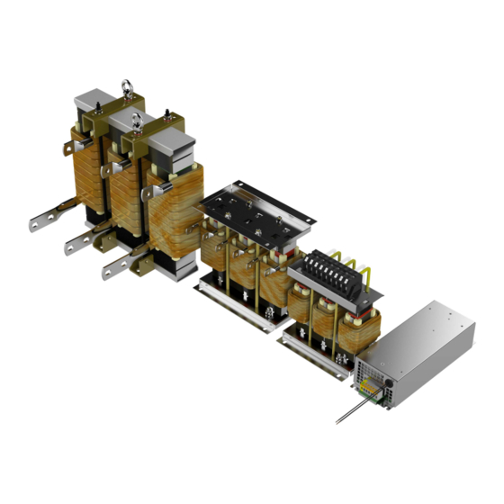
PRODUcT DEScRIPTION 2 Product Description This instructions for use describe the output filters of the COMBILINE Z2 series. These are consisting of a motor choke, a capacitor module and an appropriate cable set. component Material number Z2 motor choke xxZ2F04-1003 Z2 capacitor module 00Z2G24-xxxx Z2 cable set 00Z2T09-xxxx The use of the motor choke is also possible on its own. It reduces the ripple of the motor current and the dv/dt to protect the motor insulation. -
Page 15: Product Features
PRODUcT DEScRIPTION 2.3 Product features This instructions for use describe the components of the Z2 output filters: Device type: Output filter Series: COMBILINE Z2 Application range: 0...1600 Hz The COMBILINE Z2 output filters are characterized by the following features: When using a motor choke Reduction of the: • rate of voltage rise (dv/dt) • motor bearing currents • motor losses • motor noises When using an output filter Sinusoidal output voltage, resulting in a reduction of: •... -
Page 16: Technical Data
OPERATING cONDITIONS 3 Technical Data 3.1 Operating conditions 3.1.1 climatic environmental conditions Storage Standard class Notes Ambient temperature EN 60721-3-1 -25…55 °C Relative humidity 5…95 % (without condensation) EN 60721-3-1 Storage height – – max. 3000 m above sea level Transport Standard class... -
Page 17: Mechanical Environmental Conditions
OPERATING cONDITIONS 3.1.2 Mechanical environmental conditions Storage Standard class Notes Vibration amplitude 1.5 mm (2…9 Hz) Vibration limits EN 60721-3-1 Acceleration amplitude 5 m/s² (9…200 Hz) Shock limit values EN 60721-3-1 40 m/s²; 22 ms Transport Standard class Notes Vibration amplitude 3.5 mm (2…9 Hz) Vibration limits Acceleration amplitude 10 m/s²... -
Page 18: Device Data
DEVIcE DATA 3.2 Device data 3.2.1 Mechanical data of the motor chokes Typ. Tightening torque connection conductor in Nm / lb inch With Material cross- temperature number section in switch Type U, V, W U, V, W mm² / AWG 07Z2F04-1003 —... -
Page 19: Electrical Data Of The Motor Chokes
DEVIcE DATA 3.2.2 Electrical data of the motor chokes Typically Frequency power loss Material current Inductance Resistance Frequency range number in A in mH in mΩ in Hz at 600Hz at 800Hz at 1600Hz in Hz in W in W in W 07Z2F04-1003 26.5... -
Page 20: Mechanical Data Of The Capacitor Modules
DEVIcE DATA 3.2.3 Mechanical data of the capacitor modules connection Tightening torque in Nm / lb inch Material number L1, L2 (N), L3 L1, L2 (N), L3 00Z2G24-0005 00Z2G24-0015 00Z2G24-0025 00Z2G24-0035 00Z2G24-0045 00Z2G24-0055 00Z2G24-0065 Push-Lock Crimp connector 00Z2G24-0006 Terminal — 2.5 / 21.1 3 x 10 mm²... -
Page 21: Electrical Data Of The Capacitor Modules
DEVIcE DATA 3.2.4 Electrical data of the capacitor modules Max. current @ fmax capacity Material number Max. frequency in Hz in A in µF 00Z2G24-0005 0.21 0.0226 00Z2G24-0015 0.45 0.05 00Z2G24-0025 0.68 0.073 00Z2G24-0035 0.11 00Z2G24-0045 1.45 0.157 00Z2G24-0055 0.227 00Z2G24-0065 0.33 00Z2G24-0006... -
Page 22: Technical Data Of The Cable Sets
DEVIcE DATA 3.2.5 Technical data of the cable sets Cupal washers must be used between the aluminium connection and the copper line at the capacitor connection => „Connecting example for capacitor modules with M12 screw connection“. conductor Max. current cable lengths Material number cross-section in conductor connection... -
Page 23: Possible Combination Of Output Filters
DEVIcE DATA 3.2.6 Possible combination of output filters Motor choke capacitor modules and cable set cur- Size Material 0...600 Hz 0...800 Hz 0...1000 Hz 0...1200 Hz 0...1600 Hz rent number = 6 kHz = 8 kHz = 10 kHz = 12 kHz = 16 kHz in A 00Z2G24-0006... -
Page 24: Table 10: Possible Combination Of Output Filters
DEVIcE DATA Motor choke capacitor modules and cable set cur- Size Material 0...600 Hz 0...800 Hz 0...1000 Hz 0...1200 Hz 0...1600 Hz rent number = 6 kHz = 8 kHz = 10 kHz = 12 kHz = 16 kHz in A 00Z2G24-0033 00Z2G24-0052 00Z2G24-0032... -
Page 25: Dimensions And Weights
DIMENSIONS AND WEIGHTS 3.3 Dimensions and weights 3.3.1 Motor chokes size 07 to 12 Mounting direction Size Weight 07Z2F04-1003 09Z2F04-1003 — 10Z2F04-1003 12Z2F04-1003 Figure 1: Dimensions and weights motor chokes size 07 to 12 All dimensions in mm; all weights in kg. -
Page 26: Motor Chokes Size 13 To 19
DIMENSIONS AND WEIGHTS 3.3.2 Motor chokes size 13 to 19 Mounting direction Size Weight 13Z2F04-1003 14Z2F04-1003 15Z2F04-1003 16Z2F04-1003 17Z2F04-1003 10.0 18Z2F04-1003 11.2 19Z2F04-1003 11.7 Figure 2: Dimensions and weights motor chokes size 13 to 19 All dimensions in mm; all weights in kg. -
Page 27: Motor Chokes Size 20 To 22
DIMENSIONS AND WEIGHTS 3.3.3 Motor chokes size 20 to 22 Mounting direction Size Weight 20Z2F04-1003 15.0 21Z2F04-1003 17.3 22Z2F04-1003 17.0 Figure 3: Dimensions and weights motor chokes size 20 to 22 All dimensions in mm; all weights in kg. -
Page 28: Motor Chokes Size 23 To 30
DIMENSIONS AND WEIGHTS 3.3.4 Motor chokes size 23 to 30 Mounting direction Size Weight 23Z2F04-1003 10.5 32.0 24Z2F04-1003 10.5 32.8 25Z2F04-1003 10.5 35.0 26Z2F04-1003 10.5 41.0 27Z2F04-1003 10.5 45.0 28Z2F04-1003 10.5 58.5 29Z2F04-1003 10.5 62.0 30Z2F04-1003 10.5 72.0 Figure 4: Dimensions and weights motor chokes size 23 to 30 All dimensions in mm;... -
Page 29: Capacitor Modules In Housing
DIMENSIONS AND WEIGHTS 3.3.5 capacitor modules in housing Material number 00Z2G24-00x5, 00Z2G24-00x6, 00Z2G24-00x7 Weight 1.6 kg Dimensions All dimensions in mm Figure 5: Dimensions and weight of capacitor modules in housing Installation position variable. -
Page 30: Capacitor Module With A Power Capacitor
DIMENSIONS AND WEIGHTS 3.3.6 capacitor module with a power capacitor Mounting direction Material number 00Z2G24-00x1 Weight 5.6 kg Dimensions All dimensions in mm Figure 6: Dimensions and weight capacitor module with a power capacitor cAUTION Transport instructions ► Use only the recessed grips for transport. -
Page 31: Capacitor Module With Two Power Capacitors
DIMENSIONS AND WEIGHTS 3.3.7 capacitor module with two power capacitors Mounting direction Material number 00Z2G24-00x2 Weight 11.6 kg Dimensions All dimensions in mm Figure 7: Dimensions and weight capacitor module with two power capacitors cAUTION Transport instructions There is a risk of injury when lifting at the bus bar. ►... -
Page 32: Capacitor Module With Three Power Capacitors
DIMENSIONS AND WEIGHTS 3.3.8 capacitor module with three power capacitors Mounting direction Material numbers 00Z2G24-00x3 Weight 17.7 kg Dimensions All dimensions in mm Figure 8: Dimensions and weight capacitor module with three power capacitors cAUTION Transport instructions There is a risk of injury when lifting at the bus bar. ►... -
Page 33: Capacitor Module With Four Power Capacitors
DIMENSIONS AND WEIGHTS 3.3.9 capacitor module with four power capacitors Mounting direction Material numbers 00Z2G24-00x4 Weight 22.5 kg Dimensions All dimensions in mm Figure 9: Dimensions and weight capacitor module with four power capacitors cAUTION Transport instructions There is a risk of injury when lifting at the bus bar. ►... -
Page 34: Installation And Connection
INSTALLATION AND cONNEcTION 4 Installation and connection NOTICE Destruction of the motor filter ! ► The connecting cables must be fixed with a distance of 100 mm in order to ensure vibration resistance. Information about the wiring • Keep the connections between the drive converter and output filter or motor choke as short as possible. • Do not lay any other cables parallel to the motor cables. •... -
Page 35: Schematic Diagram With Output Filter
INSTALLATION AND cONNEcTION 4.2 Schematic diagram with output filter ① ② ③ ④ ⑤ T1 T2 T1 T2 U1.2 U1.1 V1.2 V1.1 W1.2 W1.1 – – U1.2 U1.3 V1.2 V1.3 W1.2 W1.3 Legend ① Drive converter ② Motor choke Output filter ③... -
Page 36: Overtemperature Shutdown
INSTALLATION AND cONNEcTION 4.3 Overtemperature shutdown In order to protect the system against overtemperatures, the chokes from size 25 are equipped with temperature switches. This must be connected with the input terminals T1/T2 of the drive converter. 4.3.1 Rated data Nc contact temperature monitoring contact Data Tripping temperature... -
Page 37: Connection Of The Motor Chokes
INSTALLATION AND cONNEcTION 4.4 connection of the motor chokes 4.4.1 connection of the motor chokes size 07 to 12 U1.2 U1.2 V1.2 V1.2 W1.2 W1.2 U1.1 V1.1 W1.1 Legend Protective earth connection U1.1, V1.1, W1.1 Input motor choke at the stranded wires U1.2, V1.2, W1.2 Output motor choke at the terminal block Figure 12: Connection of the motor chokes size 07 to 12... -
Page 38: Connection Of The Motor Chokes Size 13 To 19
INSTALLATION AND cONNEcTION 4.4.2 connection of the motor chokes size 13 to 19 Legend Protective earth connection U1.1, V1.1, W1.1 Input motor choke U1.2, V1.2, W1.2 Output motor choke Figure 13: Connection of the motor chokes size 13 to 19... -
Page 39: Connection Of The Motor Chokes Size 20 To 22
INSTALLATION AND cONNEcTION 4.4.3 connection of the motor chokes size 20 to 22 U1.1 U1.2 V1.1 V1.2 W1.1 W1.2 Legend Protective earth connection U1.1, V1.1, W1.1 Input motor choke U1.2, V1.2, W1.2 Output motor choke Figure 14: Connection of the motor chokes size 20 to 22... -
Page 40: Connection Of The Motor Chokes Size 23 To 30
INSTALLATION AND cONNEcTION 4.4.4 connection of the motor chokes size 23 to 30 U1.1 U1.2 V1.1 V1.2 W1.1 W1.2 Legend Protective earth connection U1.1, V1.1, W1.1 Input motor choke U1.2, V1.2, W1.2 Output motor choke Figure 15: Connection of the motor chokes size 23 to 30 Motor chokes of sizes 25 to 30 have a temperature switch (NC). -
Page 41: Connection Of The Capacitor Modules
INSTALLATION AND cONNEcTION 4.5 connection of the capacitor modules 4.5.1 connecting example for capacitor modules with M12 screw connection Legend ① Nut for M12 screw ① ② Brass disc ③ Ring crimp connector ④ Cupal-washer (copper side top) ② ⑤ Aluminium sheet ③... -
Page 42: Connection Of The Capacitor Module With A Power Capacitor
INSTALLATION AND cONNEcTION 4.5.3 connection of the capacitor module with a power capacitor Legend Protective earth connection via connection point on the retaining plate 3 x M12 bolt Capacitor connections U1.3, V1.3, W1.3 Figure 18: Connection of the capacitor module with a power capacitor The 3 phases can be contacted at the 3 connection points. -
Page 43: Connection Of The Capacitor Module With Three Power Capacitors
INSTALLATION AND cONNEcTION 4.5.5 connection of the capacitor module with three power capacitors Legend Protective earth connection via connection point on the retaining plate 3 x FlatAL 80x2mm; Capacitor connection for M12 screw ⌀ Drilling: = 13mm Figure 20: Connection of the capacitor module with three power capacitors The 3 phases can be contacted at the 3 connection points. -
Page 44: Connection Of The Capacitor Module With Four Power Capacitors
INSTALLATION AND cONNEcTION 4.5.6 connection of the capacitor module with four power capacitors Legend Protective earth connection via connection point on the retaining plate 3 x FlatAL 80x2mm; Capacitor connection for M12 screw ⌀ Drilling: = 13mm Figure 21: Connection of the capacitor module with four power capacitors The 3 phases can be contacted at the 3 connection points. -
Page 45: Transport Of The Motor Chokes From Size 23
INSTALLATION AND cONNEcTION 4.6 Transport of the motor chokes from size 23 The chokes of sizes 23...30 are supplied with lifting eyes. These serve to accommodate the appropriate lifting devices for the transport. WARNING Incorrect chain angle damages the lifting eyes ! ►... -
Page 46: Control Cabinet Installation
INSTALLATION AND cONNEcTION 4.7 control cabinet installation Power loss for the control cabinet dimension => „Electrical data of the motor chokes“. lower value can be used here depending on the load / frequency. NOTICE Destruction of the output filters due to overheating! ►... -
Page 47: Ventilation Of The Motor Chokes From Size 25
INSTALLATION AND cONNEcTION 4.7.3 Ventilation of the motor chokes from size 25 Motor chokes must be ventilated from size 25 and from an operating frequency of 600 Hz. Ventilation must be in the lower third of the motor choke height. The air flow must be at least 15 m³/min. Legend 1/3 of the motor choke height Figure 23: Ventilation of the motor chokes from size 25... -
Page 48: Installation Clearances For Wall Mounting For Capacitors 00Z2G24-00X5, 00Z2G24-00X6, 00Z2G24-00X7 And Motor Chokes 07
INSTALLATION AND cONNEcTION 4.7.4 Installation clearances for wall mounting for capacitors 00Z2G24-00x5, 00Z2G24-00x6, 00Z2G24-00x7 and motor chokes 07...12Z2F04-1003 Dimen- Installation distances Distance in mm Distance in inch sion Figure 24: Installation clearances for wall mounting 4.7.5 Installation clearances for floor mounting for capacitors 00Z2G24-00x1, 00Z2G24-00x2, 00Z2G24- 00x3, 00Z2G24-00x4 and motor chokes 13...30Z2F04-1003 Dimen-... -
Page 49: Certification
61800-5-1. 5.2 UL certification Acceptance according to UL is marked at KEB filters and chokes with the adjacent logo on the nameplate. To be conform according to UL for use on the North American and Canadian Market the following additionally instructions must be observed (original text of the UL-File):... - Page 50 cERTIFIcATION • Use 75°C Copper Conductors Only CSA: For Canada, this information must be provided on the nameplate (not re- quired for CSA if rated 30A or less). This marking is only applicable for all power field wiring terminals. • For Use in a Pollution Degree 2 environment For installations according to Canadian National Standard C22.2 No.
-
Page 51: Revision History
REVISION HISTORy 6 Revision History Version Date Description 2018-09 Completion of pre-series 2019-02 Completion of the series version 2020-01 Corrections to the drawings; editorial changes 2020-06 Dimensions adapted to size 23-26Z2; editorial changes... - Page 52 NOTIZEN...
- Page 53 Tel: +33 149620101 Fax: +33 145767495 c / Mitjer, Nave 8 - Pol. Ind. LA MASIA E-Mail: info@keb.fr Internet: www.keb.fr 08798 Sant Cugat Sesgarrigues (Barcelona) Spain Tel: +34 93 8970268 Fax: +34 93 8992035 E-Mail: vb.espana@keb.de Germany Geared Motors KEB Antriebstechnik GmbH...
- Page 54 Automation with Drive www.keb.de KEB Automation KG Suedstrasse 38 32683 Barntrup Tel. +49 5263 401-0 E-Mail: info@keb.de...
Need help?
Do you have a question about the COMBILINE Z2 Series and is the answer not in the manual?
Questions and answers