Sign In
Upload
Manuals
Brands
KEB Manuals
Water Filtration Systems
COMBILINE 23Z2F04-1003
KEB COMBILINE 23Z2F04-1003 Manuals
Manuals and User Guides for KEB COMBILINE 23Z2F04-1003. We have
1
KEB COMBILINE 23Z2F04-1003 manual available for free PDF download: Instructions For Use Manual
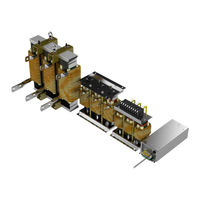
KEB COMBILINE 23Z2F04-1003 Instructions For Use Manual (54 pages)
Output Filter
Brand:
KEB
| Category:
Water Filtration Systems
| Size: 9.64 MB
Table of Contents
Preface
3
Signal Words and Symbols
3
More Symbols
3
Laws and Guidelines
4
Warranty and Liability
4
Support
4
Copyright
4
Table of Contents
5
List of Figures
7
List of Tables
8
Standards for Emc Components
9
Product Standards
9
Basic Standards
9
General Standards
9
1 Basic Safety Instructions
10
Target Group
10
Transport, Storage and Proper Use
10
Installation
11
Electrical Connection
12
Start-Up and Operation
12
Repair
13
Disposal
13
2 Product Description
14
Specified Application
14
Unintended Use
14
Product Features
15
3 Technical Data
16
Operating Conditions
16
Climatic Environmental Conditions
16
Table 1: Climatic Environmental Conditions
16
Mechanical Environmental Conditions
17
Chemical/Mechanical Active Substances
17
Electrical Operating Conditions
17
Device Classification
17
Table 2: Mechanical Environmental Conditions
17
Table 3: Chemical/Mechanical Active Substances
17
Table 4: Device Classification
17
Device Data
18
Mechanical Data of the Motor Chokes
18
Table 5: Mechanical Data of the Motor Chokes
18
Electrical Data of the Motor Chokes
19
Table 6: Electrical Data of the Motor Chokes
19
Mechanical Data of the Capacitor Modules
20
Table 7: Mechanical Data of the Capacitor Modules
20
Electrical Data of the Capacitor Modules
21
Table 8: Electrical Data of the Capacitor Modules
21
Technical Data of the Cable Sets
22
Table 9: Technical Data of the Cable Sets
22
Possible Combination Of Output Filters
23
Table 10: Possible Combination of Output Filters
24
Dimensions and Weights
25
Motor Chokes Size 07 to 12
25
Figure 1: Dimensions and Weights Motor Chokes Size 07 to 12
25
Motor Chokes Size 13 to 19
26
Figure 2: Dimensions and Weights Motor Chokes Size 13 to 19
26
Motor Chokes Size 20 to 22
27
Figure 3: Dimensions and Weights Motor Chokes Size 20 to 22
27
Motor Chokes Size 23 to 30
28
Figure 4: Dimensions and Weights Motor Chokes Size 23 to 30
28
Capacitor Modules in Housing
29
Figure 5: Dimensions and Weight of Capacitor Modules in Housing
29
Capacitor Module with a Power Capacitor
30
Figure 6: Dimensions and Weight Capacitor Module with a Power Capacitor
30
Capacitor Module with Two Power Capacitors
31
Figure 7: Dimensions and Weight Capacitor Module with Two Power Capacitors
31
Capacitor Module with Three Power Capacitors
32
Figure 8: Dimensions and Weight Capacitor Module with Three Power Capacitors
32
Capacitor Module with Four Power Capacitors
33
Figure 9: Dimensions and Weight Capacitor Module with Four Power Capacitors
33
4 Installation and Connection
34
Schematic Diagram with Motor Choke
34
Figure 10: Schematic Diagram with Motor Choke
34
Schematic Diagram with Output Filter
35
Figure 11: Schematic Diagram with Output Filter
35
Overtemperature Shutdown
36
Rated Data NC Contact Temperature Monitoring
36
Table 11: Rated Data NC Contact
36
Connection of the Motor Chokes
37
Connection of the Motor Chokes Size 07 to 12
37
Figure 12: Connection of the Motor Chokes Size 07 to 12
37
Connection of the Motor Chokes Size 13 to 19
38
Figure 13: Connection of the Motor Chokes Size 13 to 19
38
Connection of the Motor Chokes Size 20 to 22
39
Figure 14: Connection of the Motor Chokes Size 20 to 22
39
Connection of the Motor Chokes Size 23 to 30
40
Figure 15: Connection of the Motor Chokes Size 23 to 30
40
Connection of the Capacitor Modules
41
Connecting Example for Capacitor Modules with M12 Screw Connection
41
Connection of the Capacitor Module in the Housing
41
Figure 16: Connecting Example for Capacitor Modules with M12 Screw Connection
41
Figure 17: Connection of the Capacitor Module in the Housing
41
Connection of the Capacitor Module with a Power Capacitor
42
Connection of the Capacitor Module with Two Power Capacitors
42
Figure 18: Connection of the Capacitor Module with a Power Capacitor
42
Figure 19: Connection of the Capacitor Module with Two Power Capacitors
42
Connection of the Capacitor Module with Three Power Capacitors
43
Figure 20: Connection of the Capacitor Module with Three Power Capacitors
43
Connection of the Capacitor Module with Four Power Capacitors
44
Figure 21: Connection of the Capacitor Module with Four Power Capacitors
44
Transport of the Motor Chokes from Size 23
45
Figure 22: Transport of a Motor Choke
45
Control Cabinet Installation
46
Installation Position of the Motor Chokes
46
Installation Position of the Capacitor Modules
46
Ventilation of the Motor Chokes from Size 25
47
Figure 23: Ventilation of the Motor Chokes from Size 25
47
Installation Clearances for Wall Mounting for Capacitors 00Z2G24-00X5, 00Z2G24-00X6, 00Z2G24-00X7 and Motor Chokes 07
48
Installation Clearances for Floor Mounting for Capacitors 00Z2G24-00X1, 00Z2G24-00X2, 00Z2G24-00X3, 00Z2G24-00X4 and Motor Chokes 13
48
Figure 24: Installation Clearances for Wall Mounting
48
Figure 25: Installation Clearances for Floor Mounting
48
5 Certification
49
Ce-Marking
49
UL Certification
49
6 Revision History
51
Advertisement
Advertisement
Related Products
KEB COMBILINE 20Z2F04-1003
KEB COMBILINE 21Z2F04-1003
KEB COMBILINE 22Z2F04-1003
KEB COMBILINE 24Z2F04-1003
KEB COMBILINE 25Z2F04-1003
KEB COMBILINE 26Z2F04-1003
KEB COMBILINE 27Z2F04-1003
KEB COMBILINE 28Z2F04-1003
KEB COMBILINE 29Z2F04-1003
KEB 27E6T60-1150
KEB Categories
DC Drives
Controller
Control Unit
Inverter
Media Converter
More KEB Manuals
Login
Sign In
OR
Sign in with Facebook
Sign in with Google
Upload manual
Upload from disk
Upload from URL