Table of Contents
Advertisement
Quick Links
Advertisement
Table of Contents

Subscribe to Our Youtube Channel
Related Manuals for CAE Healthcare Vimedix Cardiac


Summary of Contents for CAE Healthcare Vimedix Cardiac
- Page 1 Vimedix Cardiac ™ Vimedix Abdo ™ Vimedix Ob/Gyn ™ User Guide v1.16...
- Page 2 Copyright © CAE Healthcare Academy 2016. All rights reserved. No part of this document may be reproduced without written consent from CAE Healthcare Academy. 905K800152 v1.16...
- Page 3 “ ” means any and all scientific and technical information which is in the possession of, or belonging to, CAE Healthcare and relating to the Product, including without limitation, all Data, Software, trade secrets, know-how, processes, methodologies, samples, components, analyses, compilations, guides and other information or documents prepared by...
- Page 4 2.2. Without limiting the foregoing or any other terms in this License, Licensee shall, and shall ensure that any Authorized Users: 2.3. Except for the License granted herein, CAE Healthcare grants no express or implied right under any patent, copyright, mask work right, trademark, know how or other intellectual property rights. The Licensee shall not obtain any rights to CAE Healthcare’s property, or any part thereof, by implication,...
- Page 5 Licensee wishes to opt-out of permitting CAE Healthcare from having access to Collected Data, Licensee must inform CAE Healthcare of this requirement. 3.2. Upon the request of CAE Healthcare, Licensee agrees to provide CAE Healthcare, from time to time, Feedback with comments, suggestions, data, information or feedback (“...
- Page 6 Product. In addition, should Licensee fail to comply with any other terms and conditions of this Agreement and such failure is not cured within thirty (30) days after receipt of CAE Healthcare’s written notice, CAE Healthcare may terminate this Agreement immediately.
- Page 7 6.1. Licensee acknowledges that the Software and Data constitute a special, irreplaceable asset of great value to CAE Healthcare, and that a breach, in any way, of any of Licensee’s obligations under Sections 2 (License), and 5 (Non-Disclosure) hereof would cause serious and irreparable harm to CAE Healthcare which may not be adequately compensated for in damages.
- Page 8 Software and/or Data by the U. S. Government, or any of its units or agencies shall be governed solely by the terms of this License and the HEPGTC. Any technical data provided by CAE Healthcare with the Product that is not covered by the above provisions is deemed to be "technical data-commercial items"...
- Page 9 End User License Agreement designated, shall be a waiver of such right or remedy to which the party is entitled, nor shall it in any way affect the right of the party to subsequently enforce such provisions. Modification: 10.6 No provision of this License shall be deemed waived, amended or modified by either party unless the waiver, amendment or modification is in writing and signed by each of the parties to this License.
- Page 10 Vimedix ™ End User License Agreement viii...
-
Page 11: Specifications
Specifications PECIFICATIONS Male Mannequin Size Approximately 31 in x 17 in (78 cm x 43 cm) Weight Bob 1.1, 1.2 72 lbs (32.7 kg) Bob 1.3 31.5 lbs (14.3 kg) Computer Size 17.5 x 8.0 x 20.7 in (44.4 x 20.3 x 52.5 cm) Ambient Temperature Range C-40 C (41... -
Page 12: Cautions/Warnings
• Do not insert any USB devices other than a USB storage device (memory stick, flash drive). Other USB devices such as phone or mp3 chargers may create a simulator error. • All equipment inquiries should be directed to the product manufacturer: CAE Healthcare 6300 Edgelake Drive Sarasota, FL 34240 viii... -
Page 13: Table Of Contents
Table of Contents ABLE OF ONTENTS END USER LICENSE AGREEMENT FOR CAE HEALTHCARE PRODUCTS ..........i Specifications ........................vii Male Mannequin ........................vii Size ................................vii Weight..............................vii Computer...........................vii Size ................................vii Ambient Temperature Range.........................vii Electrical ..............................vii Display ..........................vii Size ................................vii Ambient Temperature Range.........................vii Cautions/Warnings .......................viii Table of Contents...................... -
Page 14: Table Of Contents
Table of Contents Phased Array Probe..........................8 Transesophageal Echocardiography (TEE) Probe..................8 Curvilinear Probe............................. 9 Endovaginal Probe ..........................9 Mannequin Head ..........................10 Mouthpiece............................10 Additional Case and Pathology Packages ....................11 Display Cart ............................11 Mannequin Carrying Case ........................11 Computer Carrying Case........................ - Page 15 Table of Contents Interface Overview ......................31 Augmented Reality Display........................32 Simulation Panel........................... 33 Ultrasound Display..........................37 Ultrasound Panel ..........................38 Control Panel ............................44 Selecting a Virtual Probe Option..................45 Using the Mouse Controls ........................45 Using the Probe............................. 47 Using the Probe Pause Feature......................48 Loading Pathologies......................48 Loading a Pathology in Standard Mode ....................
- Page 16 Table of Contents Using the Zoom Feature......................97 Selecting a Convention ..................... 100 Cardiology and Anesthesiology Convention ..................101 Radiology Convention......................... 102 Mayo Clinic Cardiac Convention ......................102 Cardiac Pediatric Convention....................... 103 Using the Measurement Features ..................104 Using the Electronic Caliper......................... 105 Using the Area Measurement Tool ......................
- Page 17 Table of Contents Using Capture Controls ..................... 142 Capturing Images..........................143 Recording Video..........................143 Modifying Image and Video Capture Settings ..................144 Viewing Image Captures ........................145 Transferring Image Captures and Videos..................... 147 Managing Network Settings....................149 Configuring Proxy Settings........................151 Configuring Custom Network Settings ....................
- Page 18 Table of Contents Simulation Panel..........................165 Ultrasound Display..........................169 Ultrasound Panel ..........................170 Selecting a Virtual Probe Option..................176 Using the Mouse Controls ........................176 Using the Probe........................... 178 Using the Endovaginal Probe ......................178 Using the Probe Pause Feature......................179 Loading Pathologies......................
- Page 19 Table of Contents Selecting a Convention ..................... 228 Cardiology and Anesthesiology Convention ..................229 Radiology Convention......................... 230 Mayo Clinic Cardiac Convention ......................231 Cardiac Pediatric Convention....................... 231 Using the Measurement Features ..................232 Using the Electronic Caliper......................... 233 Using the Area Measurement Tool ...................... 235 Using the Circumference Measurement Tool..................
- Page 20 Table of Contents Managing Network Settings....................272 Configuring Proxy Settings........................273 Configuring Custom Network Settings ....................274 Modifying Simulator Settings.................... 274 Language............................275 Patient Name............................275 Hospital Name ............................ 275 Use Pressure Sensor ..........................276 Metrics Capture Interval........................276 Image Quality............................276 Use Popup Toolbar ..........................
- Page 21 Table of Contents Using the Probe........................... 302 Using the Endovaginal Probe ......................302 Using the Probe Pause Feature......................303 Loading Pathologies......................304 Loading a Pathology in Standard Mode ....................305 Loading a Pathology in Stealth Mode ....................312 Selecting Modalities ......................314 Using Target Cut Planes ....................
- Page 22 Table of Contents Using the Electronic Caliper......................... 358 Using the Area Measurement Tool ...................... 360 Using the Circumference Measurement Tool..................362 Editing a Measurement..................... 364 Deleting a Measurement....................365 Using Reports........................367 Creating a Report ..........................368 Entering Report Information....................... 369 Viewing an OBGYN Report........................
- Page 23 Table of Contents Hospital Name ............................ 400 Use Pressure Sensor ..........................401 Metrics Capture Interval........................401 Image Quality............................401 Use Popup Toolbar ..........................401 Use Male ............................. 401 Time and Date............................. 401 Layout on start-up ..........................401 Probe Type ............................401 Override Default Startup Values ......................
- Page 24 Table of Contents Stay Comfortable ..........................420 Safety and Warnings....................421 AC adapter Safety..........................421 Battery Safety ............................. 421 Potentially Explosive Atmospheres ..................... 421 Personal Medical Devices ........................421 Heat Related Concerns ........................422 Photo Sensitive Seizures ........................422 Skin Irritation ............................423 Menu Hierarchy........................
- Page 25 Table of Contents Cardiac Package 1 ......................441 Cardiac Package 2......................442 Cardiac Package 3......................442 Cardiac Package 4......................443 Emergency Physicians Mix & Match Package 1 ..............443 Montreal Heart Institute (MHI) ..................444 Montreal Heart Institute (MHI) Acute Complex Pathology+ ..........444 Emergency Ultrasound Package ..................
- Page 26 Table of Contents xxii...
-
Page 27: Introduction
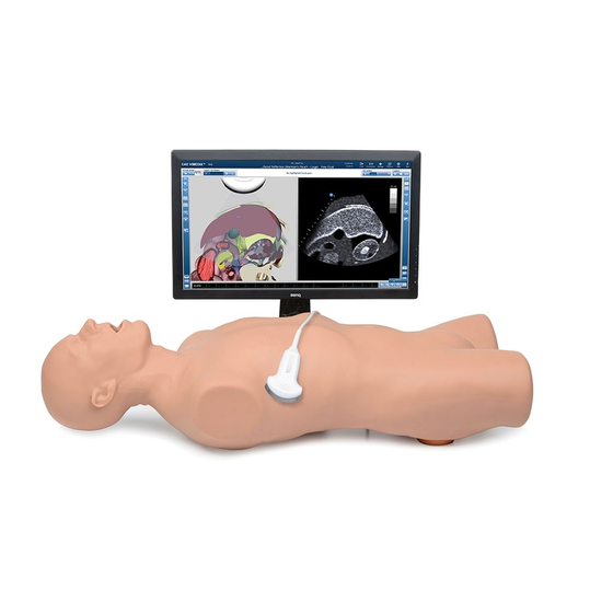
Introduction NTRODUCTION The Vimedix Ultrasonography Simulator User Guide provides information about setting up the simulator, navigating the user interface, troubleshooting, performing care and maintenance and installing updates. Using real-time dynamic imaging and a custom designed mannequin, the Vimedix Ultrasonography Simulator provides healthcare professionals with an unparalleled training environment for scanning the thoracic, abdominal and pelvic cavities with basic to complex cases. -
Page 28: Contained In This User Guide
Vimedix ™ Introduction Contained in this User Guide This User Guide has been designed for quick access to information on how to use and maintain the Vimedix Simulator. Please be sure to read and follow the Cautions and Warnings on the pages preceding the Table of Contents. -
Page 29: Equipment Overview
Equipment Overview QUIPMENT VERVIEW Users can choose from different basic platforms for the Vimedix Ultrasonography Simulator: • Vimedix Cardiac Transthoracic Echocardiography (TTE) º Transesophageal Echocardiography (TEE) º • Vimedix Abdo Regular Abdominal º FAST Abdominal º After a basic platform is purchased, additional modules can be purchased as a system upgrade. -
Page 30: The Mannequins
Equipment Overview The Mannequins For the Cardiac TTE or TEE platforms, CAE Healthcare provides a life-size male torso and a cable that connects to the computer to register probe activity and communicate with the Vimedix simulator. The mannequin has realistic tactile features including a depressible abdomen, palpable ribs and sternum and depressible interspaces. -
Page 31: Female Mannequin
The Bob 1.3 Male Mannequin Female Mannequin For the Vimedix Ob/Gyn ultrasound simulator, CAE Healthcare provides a full-size female torso and cable that connects to the computer to register probe activity and communicate with the Vimedix simulator. The female mannequin features including some depressibility in the abdomen for performing pelvic ultrasounds. -
Page 32: Computer
Vimedix ™ Equipment Overview Computer Along with the mannequin and probe, the computer is one of the essential components of the Vimedix. The operating system is solely programmed to run the Vimedix software and receive updates. The Vimedix Computer Computer Power Supply Cord The computer power supply cord is used to connect the computer to a surge-protected power source. -
Page 33: Display Monitor
Equipment Overview Display Monitor The display monitor shows the interface and the user’s probe activity. DVI Connector Cable The DVI connector cable connects the display monitor to the computer. Monitor Power Supply Cord The monitor power supply cord connects the computer to a surge-protected power source. Ethernet Cable The Ethernet cable connects the computer to the Internet. -
Page 34: Phased Array Probe
Vimedix ™ Equipment Overview Phased Array Probe The Phased Array probe is provided for users who choose the TTE module. The Phased Array probe simulates the functionality of a real probe, incorporating a pressure sensor that can be turned on or off, depending on the training need. -
Page 35: Curvilinear Probe
Equipment Overview Curvilinear Probe The curvilinear probe is available for users who purchase the abdominal module upgrade or the Vimedix Ob/Gyn ultrasound simulator. The Curvilinear Probe Endovaginal Probe The endovaginal probe is available for users who purchase the 8-week module for the Vimedix Ob/Gyn ultrasound simulator. -
Page 36: Mannequin Head
Vimedix ™ Equipment Overview Mannequin Head The mannequin head is provided for users who choose the TEE module. (Bob 1.3 has a one-piece head and torso) The Mannequin Head Mouthpiece The mouth piece is provided for users who choose the TEE module. Designed to be used with the mannequin head, the component simulates a mouthpiece used during transesophageal echocardiography. -
Page 37: Additional Case And Pathology Packages
Additional case and pathology packages are available for the Vimedix simulator. Display Cart CAE Healthcare highly recommends that users purchase the moving display cart designed for the Vimedix simulator. The cart dimensions are 40.5 x 25.5 x 32.25 inches, and the cart requires assembly prior to use. - Page 38 Vimedix ™ Equipment Overview...
-
Page 39: Before Beginning Setup
Setup ETUP Setting Up the Vimedix Simulator Place the Mannequin in the Work Area Attach the Head (TEE Users Only) Place the Computer in the Work Area Connect the Mannequin to the Computer Connect the Computer to a Power Supply Connect the Monitor to a Power Supply Connect the Monitor to the Computer Connect the Mouse and Keyboard... -
Page 40: Step 1: Place The Mannequin In The Work Area
Vimedix ™ Setup Step 1: Place the Mannequin in the Work Area Locate a work area for the Vimedix. A permanent location is recommended so the equipment does not need to be transported. Place the mannequin flat on its back on a flat surface. For the male mannequin, use a surface that can support 72 pounds (32.7 kg) such as a display cart;... -
Page 41: Step 2: Attach The Head (For Tee Users With Bob 1.1 Or Bob 1.2)
Setup To attach the stands: 1. Insert the larger stand into the holes in the upper back (arrow toward head), and the smaller stand into the holes in the lower back (arrow toward feet). 2. Ensure the stands with non-slip bottom are flat on surface. NOTE: Be careful not to lean on or move the mannequin and stands while in use. -
Page 42: Bob 1.1
Vimedix ™ Setup Bob 1.1 To attach the Bob 1.1 mannequin head to the torso: a. Locate the mannequin head. b. Position the head just below the height of the mannequin’s chest. The head The Head Positioning c. Align the tabs on the mannequin’s body with the grooves at the base of the head. -
Page 43: Bob 1.2
Bob 1.2 NOTE: Ensure the mannequin torso is placed on its stomach. If the mannequin is not on its stomach already, CAE Healthcare recommends using two people to turn the mannequin onto its stomach. The Bob 1.2 Mannequin Two Person Rotation... - Page 44 Vimedix ™ Setup a. Using the 3/8 Allen wrench provided in your shipment, remove the neck plate by turning the plastic bolt counterclockwise. The Allen wrench The plastic bolt The neck plate The Bob 1.2 Equipment b. Locate the mannequin head The head The plastic bolt The Allen wrench...
- Page 45 Setup c. With the face positioned downward, align the head with the hole at the top of the torso. The hole The head The Head Alignment d. Use one hand to support the head and use the other to place the plastic bolt in the hole.
-
Page 46: Step 3: Place The Computer In The Work Area
Vimedix ™ Setup NOTE: To avoid injury, CAE Healthcare recommends using two people to perform this Setup step. The Bob 1.2 Mannequin Two Person Rotation Step 3: Place the Computer in the Work Area Remove the computer from storage. Place the computer on a flat, level surface at least 2 feet (60 cm) away from the mannequin to prevent image distortion. -
Page 47: Step 6: Connect The Monitor To A Power Supply
Setup Step 6: Connect the Monitor to a Power Supply Connect the female end of the monitor power cord to the monitor and the male end to a surge- protected power outlet. Step 7: Connect the Monitor to the Computer To connect the monitor to the computer: a. -
Page 48: Step 8: Connect The Mouse And Keyboard
Vimedix ™ Setup Step 8: Connect the Mouse and Keyboard a. Plug the wireless USB adapter into any of the USB ports on the computer. The USB adapter The VIMEDIX Computer USB Ports b. Ensure the mouse and keyboard switches are ON and the shipping tab has been removed from the battery compartments. -
Page 49: Step 9: Connect The Ethernet Cable
Setup Step 9: Connect the Ethernet Cable To connect the Ethernet cable to the Vimedix computer: a. Connect one end of the Ethernet cable to the back panel of the computer. The Ethernet port The VIMEDIX Computer Back Panel b. Connect the other end of the Ethernet cable to the appropriate Ethernet source port. - Page 50 Vimedix ™ Setup WARNING: DO NOT connect the probe to SENSOR 2 port. The probe must be connected to the SENSOR 1 port. b. Place the probe on the mannequin’s abdomen for calibration. On the male mannequin, place the probe over the belly button on the abdomen. The probe on the mannequin’s abdomen...
-
Page 51: Step 11: Power On The Computer And Monitor
Setup When using the endovaginal probe, place the probe on the mannequin’s torso with the tip of the probe pointing towards the head of the mannequin. The endovaginal probe The Female Mannequin’s Abdomen Step 11: Power on the Computer and Monitor To power on the Vimedix computer: a. - Page 52 Vimedix ™ Setup...
-
Page 53: Starting The Simulator
Starting the Simulator TARTING THE IMULATOR Display Configuration Options Choose a Display Configuration Perform Auto Update (if available) Calibrate the Probe Accept License Agreement Once the Vimedix is turned on, the System Startup screen appears. The System Startup Screen The system begins loading and a progress bar appears. It may take several minutes for the system to load. -
Page 54: Step 1: Choose A Display Configuration
Vimedix ™ Starting the Simulator Step 1: Choose a Display Configuration In some training situations, it can be useful to have two monitors connected to the simulator. When the system detects the second monitor, the display configuration screen appears. The Display Configuration Screen To choose a display configuration: a. -
Page 55: Step 2: Perform Auto Update
Starting the Simulator c. Click the Apply button to apply the configuration. The Apply button The Apply Buttons A warning message appears if one of the monitors does not meet the 1920x1080p resolution requirement. The Resolution Warning Message The warning message is intended for notification purposes only. An incorrect resolution will not affect the user’s ability to access the simulator. -
Page 56: Step 3: Calibrate The Probe
WARNING: If the support and maintenance agreement for the simulator has expired, the auto updates are not available. It is important to maintain an active agreement with CAE Healthcare to ensure that the simulator receives the most recent updates as they become available. Contact your CAE Healthcare representative for more information. -
Page 57: Using The Multipurpose (Cardiac/Abdo) Simulator
Using the Multipurpose Simulator (Cardiac/Abdo) SING THE ULTIPURPOSE IMULATOR CARDIAC ABDO The Vimedix simulator is designed to give learners an exploratory training environment to practice using an ultrasonography machine. The male mannequin is provided for the modules: Transthoracic echocardiography (TTE), Transesophageal echocardiography (TEE), Abdominal ultrasonography, and Pleural ultrasonography. -
Page 58: Augmented Reality Display
Vimedix ™ Using the Multipurpose Simulator (Cardiac/Abdo) Augmented Reality Display The left side of the Split View interface displays an interactive, animated 3D anatomical depiction of the organs and artifacts located in the scanned area. The AR display shows a representation of the ultrasound beam placement to help the learner generate an accurate ultrasound image. -
Page 59: Simulation Panel
Using the Multipurpose Simulator (Cardiac/Abdo) Simulation Panel The buttons under the Simulation panel on the left side of the interface allow the user to customize the training experience. The Simulation Panel... - Page 60 Vimedix ™ Using the Multipurpose Simulator (Cardiac/Abdo) The expanded panel view is available and it can be accessed by deselecting the Use Popup Toolbar checkbox in the Settings window. The Simulation Panel - Expanded View For more information on expanding the panel view, see Modifying Simulator Settings.
- Page 61 Using the Multipurpose Simulator (Cardiac/Abdo) Simulation Panel Buttons The Simulation panel buttons are categorized and separated into sections by the relevance of their functions. Simulation Panel Buttons Located in the Settings section, the Lock button is used to activate the view lock feature.
- Page 62 Vimedix ™ Using the Multipurpose Simulator (Cardiac/Abdo) Simulation Panel Buttons Located in the Beam section, the Ultrasound button enables the ultrasound mode of the beam on the AR display. Located in the Beam Guide section, the Beam Guide button enables a green line and a red line on the left and right side of the beam to indicate the orientation Located in the Layout section, the Split View button activates the split...
-
Page 63: Ultrasound Display
Using the Multipurpose Simulator (Cardiac/Abdo) Ultrasound Display The right side of the Split View interface shows the ultrasound image and contains different features to achieve the desired view. The Ultrasound Display... -
Page 64: Ultrasound Panel
Vimedix ™ Using the Multipurpose Simulator (Cardiac/Abdo) Ultrasound Panel The buttons under the Ultrasound panel on the right side of the interface are used to modify and interact with the Ultrasound display. The Ultrasound Panel... - Page 65 Using the Multipurpose Simulator (Cardiac/Abdo) The expanded panel view is available and it can be accessed by deselecting the Use Popup Toolbar checkbox in the Settings window. The Ultrasound Panel - Expanded View For more information on expanding the panel view, see Modifying Simulator Settings.
- Page 66 Vimedix ™ Using the Multipurpose Simulator (Cardiac/Abdo) Ultrasound Panel Buttons The buttons are categorized and separated into sections by the relevance of their functions. Ultrasound Panel Buttons Located in the Settings section, the ECG button is used to enable or dis- able the ECG tracing feature on the bottom of the screen.
- Page 67 Using the Multipurpose Simulator (Cardiac/Abdo) Ultrasound Panel Buttons Located in the Convention section, the Cardiac Pediatric Convention button activates the cardiac pediatric convention. Located in the Measures section, the Measurements button activates the drop-down menu for the measurement options. Located in the Measures section, the Electronic Caliper button enables the electronic caliper tool to measure lengths of the anatomy in the Ultrasound display.
- Page 68 Vimedix ™ Using the Multipurpose Simulator (Cardiac/Abdo) Ultrasound Panel Buttons Located in the Doppler section, the Pulsed Wave button activates the Pulsed Wave Doppler feature in the Ultrasound display. Located in the Doppler section, the Continuous Wave button activates the Continuous Wave Doppler feature in the Ultrasound display. Located in the M-Mode section, the M-Mode button activates the M- Mode feature in the Ultrasound display.
- Page 69 Using the Multipurpose Simulator (Cardiac/Abdo) Settings Panel Buttons The Settings panel contains buttons which are relevant to the Ultrasound display. The Settings Panel When different modes are activated (Doppler, M-Mode, Biplane), the Settings panel contains additional settings buttons for the activated modes. NOTE: The Settings buttons are located in the Ultrasound panel when the Use Popup Toolbar checkbox is deselected.
-
Page 70: Control Panel
Vimedix ™ Using the Multipurpose Simulator (Cardiac/Abdo) Settings Panel Buttons Located in the Settings panel, the Doppler Settings button allows users to access the Doppler Settings window to adjust settings. Control Panel The Control panel is located in the upper-right corner of the interface. By clicking on the icons, users can load pathologies, modify connections and settings, access help tools and exit the program. -
Page 71: Selecting A Virtual Probe Option
Using the Multipurpose Simulator (Cardiac/Abdo) The Exit icon is used to shut down the simulator. Selecting a Virtual Probe Option The Virtual Probe panel contains three options: the Mouse button, the Probe button and the Probe Pause button. The Virtual Probe Options Using the Mouse Controls Click the Mouse button to control the various views of the simulator with the computer mouse. - Page 72 Vimedix ™ Using the Multipurpose Simulator (Cardiac/Abdo) NOTE: When using the expanded toolbar view, click the Viewlock button one time to deactivate/unlock the viewlock. The Viewlock button The Settings Section 2. Once the view lock is disabled, place the cursor in the AR display. 3.
-
Page 73: Using The Probe
TEE module at a later time). The transesophageal probe can only be inserted into Bob mannequins with a head attached. If the mannequin does not have a head, contact CAE Healthcare Customer Service to request a TEE head installation kit. -
Page 74: Using The Probe Pause Feature
Using the Curvilinear Probe NOTE: The curvilinear probe is only provided for users who have purchased the FAST, Abdominal or Ob/Gyn 20-week modules. Contact your CAE Healthcare sales representative to purchase one of these modules. To use the curvilinear probe, place the tip of the probe on the mannequin’s skin to obtain a view. - Page 75 Using the Multipurpose Simulator (Cardiac/Abdo) The Pathologies window appears. The Pathologies Window Users can find and load pathologies using the features in the Pathologies window. Clicking the Go to Normal button highlights the normal case in the pathology selection window.
-
Page 76: Loading A Pathology In Standard Mode
Vimedix ™ Using the Multipurpose Simulator (Cardiac/Abdo) Loading a Pathology in Standard Mode Users can load pathologies in standard mode and organize the selections using criteria in the Filters panel. The filters feature allows users to organize pathologies by Category or Availability criteria. Users have the option to narrow the pathologies displayed in the Pathologies panel based on the type of module (FAST and ICCU), area of focus (Abdominal, Cardiac and Pleural), availability (Available or Expired) or the type of mannequin (Need change of mannequin). - Page 77 Using the Multipurpose Simulator (Cardiac/Abdo) 2. Select the search criteria from the Filters panel. The Filters Panel NOTE: Information for creating Custom Filters follows this section. The pathologies update automatically in the Pathologies panel. If no criteria is selected, all available pathologies display in the Pathologies panel.
- Page 78 Vimedix ™ Using the Multipurpose Simulator (Cardiac/Abdo) The pathology selection expands. The Pathologies Window 4. Click the Load button. NOTE: Certain cases offer a Load... option to turn Modalities ON or OFF. Refer to the Selecting Modalities section for more information. The Load button The Selected Pathology...
- Page 79 Using the Multipurpose Simulator (Cardiac/Abdo) The Loading Pathology window appears. The Loading Pathology Window NOTE: When loading a Montreal Heart Institute pathology, the Pathologies Loading window contains a brief synopsis of the patient’s history and a Continue button. Users must click the Continue button after reviewing the synopsis to access the loaded pathology.
- Page 80 Vimedix ™ Using the Multipurpose Simulator (Cardiac/Abdo) 1. Click the Custom Filters tab. Custom Filters The Custom Filters Window 2. Click Add Filter.
- Page 81 Using the Multipurpose Simulator (Cardiac/Abdo) The New Filter is displayed. The New Filter The Add Filter button The Custom Filters Window 3. Double-click the New Filter to rename it. A new filter must be renamed before adding additional filters. Then, press Enter or click outside of the filter name to apply the name change.
- Page 82 Vimedix ™ Using the Multipurpose Simulator (Cardiac/Abdo) 4. Ensure the new filter is highlighted, then select (checkbox) the desired pathologies. The selected pathologies are automatically applied to the filter. custom filter selected pathologies The Custom Filters Window...
-
Page 83: Loading A Pathology In Stealth Mode
Using the Multipurpose Simulator (Cardiac/Abdo) 5. When finished, click the Pathologies tab, then select (checkbox) the desired custom filter. custom filter selected The Pathologies Window NOTE: To refresh a custom filter, from the Pathologies tab, uncheck then re-check the desired custom filter. To edit a Custom Filter: 1. - Page 84 Vimedix ™ Using the Multipurpose Simulator (Cardiac/Abdo) 1. Click the Load icon The Load Icon The Pathologies window appears. 2. Use the Pathology Codes document to find the code for the desired pathology. 3. Enter the code into the Code text box. The Load The Code button...
- Page 85 Using the Multipurpose Simulator (Cardiac/Abdo) 1. Select the desired pathology from the Pathologies panel. The Pathologies Window 2. Select the Hide pathology name on the main interface (Stealth mode) checkbox. Stealth mode checkbox The Pathologies Window 3. Click Load in the selected pathology The Load button The Selected Pathology...
-
Page 86: Accessing Additional Pathology Information
Vimedix ™ Using the Multipurpose Simulator (Cardiac/Abdo) The pathology is loaded in Stealth mode. The Loaded Pathology with Stealth Mode Activated Accessing Additional Pathology Information NOTE: This feature is only applicable to Montreal Heart Institute pathologies. The Montreal Heart Institute pathologies have supporting content, such as case presentations and medical references. -
Page 87: Selecting Modalities
Using the Multipurpose Simulator (Cardiac/Abdo) 2. Click the More Info button to access supporting content prior to loading the pathology. OR After loading the pathology, click the More Info button near the top of the loaded pathology screen. The More Info button The More Info Button on a Loaded Pathology The More Information window appears. - Page 88 Vimedix ™ Using the Multipurpose Simulator (Cardiac/Abdo) Certain cases (like the AAA Pathology Package cases) offer the option to turn Modalities ON or OFF. Select the Load... button when loading a case to turn modalities ON or OFF. Load... button The Load Modalities Option After loading the case (during imaging), click the modalities icon to access the Modality Settings window and turn modalities ON or OFF.
-
Page 89: Using Target Cut Planes
Using the Multipurpose Simulator (Cardiac/Abdo) Using Target Cut Planes Target cut planes (TCP) are reference views that learners can use to mimic correct probe positioning. Instructors can select a pre-existing TCP or create a new TCP on any case. The Ultrasound display The live beam The reference... - Page 90 Vimedix ™ Using the Multipurpose Simulator (Cardiac/Abdo) In the AR Display, the red reference ultrasound beam identifies the cut plane the learner must achieve. The ultrasound beam on the AR display and the live ultrasound image display the cut plane of the live probe.
-
Page 91: Target Cut Planes Panel Buttons
Using the Multipurpose Simulator (Cardiac/Abdo) For more information on the metrics parameters, see Metrics Parameters. Target Cut Planes Panel Buttons Target cut planes are learning tools designed to allow learners to practice techniques in the absence of an instructor. The Target Cut Planes panel has three buttons: Stop Metrics button, New button and the TCP Menu button. - Page 92 Vimedix ™ Using the Multipurpose Simulator (Cardiac/Abdo) 3. From the Target Cut Planes panel, click the New button. The New button The Target Cut Planes Panel The New Target Cut Plane window appears. By default, the name is a 10- digit auto-generated number and the TCP category is none.
- Page 93 Using the Multipurpose Simulator (Cardiac/Abdo) NOTE: Users can also create a personal TCP from the Target cut planes window by clicking on the Personal tab and clicking the New button located above the list of available personal TCPs. Personal The New button The Target Cut Planes Window The TCP is created and available in the Personal tab in the Target cut...
-
Page 94: Loading A Target Cut Plane
Vimedix ™ Using the Multipurpose Simulator (Cardiac/Abdo) Loading a Target Cut Plane Users load existing TCPs to practice achieving specific probe positions and ultrasound views. NOTE: The Vimedix simulator comes with pre-existing TCPs for the Normal pathology using the TTE probe only. - Page 95 Using the Multipurpose Simulator (Cardiac/Abdo) 2. In the Target cut planes window, select the Base or Personal tab, depending on the type of target cut plane to be loaded. The available TCPs are listed. 3. Select the TCP to load from the list. selected The Load button...
-
Page 96: Loading Multiple Target Cut Planes
Vimedix ™ Using the Multipurpose Simulator (Cardiac/Abdo) Loading Multiple Target Cut Planes Users can load multiple TCPs to practice achieving specific probe positions and ultrasound views in succession in the same manner a trained sonographer performs an ultrasound exam. To load multiple TCPs: 1. - Page 97 Using the Multipurpose Simulator (Cardiac/Abdo) The available TCPs are listed. 3. Select the TCPs to load from the list by holding down the CTRL key on the keyboard and selecting multiple TCPs. NOTE: Users can select a combination of TCPs from both the Base and Personal tabs using the CTRL key and navigating between tabs.
-
Page 98: Unloading A Target Cut Plane
Vimedix ™ Using the Multipurpose Simulator (Cardiac/Abdo) For more information on stopping metrics, see Stopping Metrics. Unloading a Target Cut Plane To unload a current TCP and return to the standard view: 1. Click the TCP menu button in the Target Cut Planes panel. The TCP Menu button The Target Cut Planes Panel... - Page 99 Using the Multipurpose Simulator (Cardiac/Abdo) Starting Metrics To record the metrics of a TCP: 1. Click the TCP menu button located in the Target Cut Planes panel. The Target cut planes window appears. Personal tab The Base tab The Show timer checkbox The Start...
- Page 100 Vimedix ™ Using the Multipurpose Simulator (Cardiac/Abdo) Stopping Metrics To stop the timer during a TCP metrics session, click the Stop Metrics button located in the Target Cut Planes panel or press the Enter key on the keyboard. The Stop Metrics button The Target Cut Planes Panel...
- Page 101 Using the Multipurpose Simulator (Cardiac/Abdo) An expanded list of metrics appears. The Metrics Summary Window...
- Page 102 Vimedix ™ Using the Multipurpose Simulator (Cardiac/Abdo) Reviewing Metrics Users can review the last probe position and the images that were last displayed during a metrics session by using the metrics review feature. To review the metrics: 1. Click the TCP and Metrics menu button located in the Target Cut Planes panel.
- Page 103 Using the Multipurpose Simulator (Cardiac/Abdo) 4. Click the Review button. The Review button The Metrics Tab The interface shows the last image recorded during the metrics session in the reference ultrasound image display. The AR and Ultrasound displays show the view from the current probe position. The mannequin placement display shows last probe's position and orientation during the metrics sessions in comparison to current probe's position and orientation.
-
Page 104: Using The View Lock Feature
Vimedix ™ Using the Multipurpose Simulator (Cardiac/Abdo) Using the View Lock Feature Click the Viewlock button, located in the Simulation panel to lock or unlock the view. The view lock is activated by default. The Viewlock The Lock button button The Unlock button The Viewlock buttons... -
Page 105: Modifying The Structures Visibility
Using the Multipurpose Simulator (Cardiac/Abdo) Modifying the Structures Visibility Users can hide structures from view during a training by modifying the checkboxes in the Structures Visibility window. To modify structures visibility: 1. Click on the Structures Visibility button located in the Simulation panel. The Structures Visibility Button NOTE: When using the expanded toolbar view, click the Structures Visibility button located in the Settings section of the Simulation panel. - Page 106 Vimedix ™ Using the Multipurpose Simulator (Cardiac/Abdo) The Structures Visibility window appears. The Structures Visibility Window 2. Uncheck the boxes in the left column to remove structures from the AR display. 3. Uncheck the boxes in the right column to remove artifacts from the Ultrasound display.
-
Page 107: Selecting A Cross Section View
Using the Multipurpose Simulator (Cardiac/Abdo) Selecting a Cross Section View Using the Cross Section View button, users can select the desired cross section view from the available options. The Cross Section The Normal View button button The Inverted button The Both Sides button The Cross Section View Options NOTE: When using the expanded toolbar view, click the desired cross section button located in the... -
Page 108: Selecting The Beam Type
Vimedix ™ Using the Multipurpose Simulator (Cardiac/Abdo) The Inverted button enables the Inverted cross section view. The Inverted Cross Section Button The Both Sides button disables the cross section view in the AR display. The Both Sides Cross Button Selecting the Beam Type Using the Beam button, users can choose from three available beam options. - Page 109 Using the Multipurpose Simulator (Cardiac/Abdo) NOTE: When using the expanded toolbar view, click on the appropriate beam button in the Beam section, located in the Simulation panel. The Beam Section The default AR beam is Semi-Transparent. A Semi-Transparent AR Beam...
- Page 110 Vimedix ™ Using the Multipurpose Simulator (Cardiac/Abdo) The Edge AR beam is similar to the Semi-Transparent AR beam, but includes a red line around the edge of the ultrasound beam. An Edge AR Beam The Ultrasound AR beam displays the structures within the ultrasound beam using an ultrasound view. An Ultrasound AR Beam...
-
Page 111: Using The Beam Guide
Using the Multipurpose Simulator (Cardiac/Abdo) Using the Beam Guide The beam guide allows users to identify the orientation of the beam using red and green lateral borders. To activate the cut plane guide, click the Beam Guide button located in the Simulation panel The Beam Guide button The Beam Guide Button... -
Page 112: Changing The Display Layout
Vimedix ™ Using the Multipurpose Simulator (Cardiac/Abdo) The green and red borders appear to show the user the orientation of the beam. The Activated Beam Guide Changing the Display Layout Using the Layout button, users can select the desired display layout from the available options. The Normal The Layout button button... - Page 113 Using the Multipurpose Simulator (Cardiac/Abdo) NOTE: When using the expanded toolbar view, click the desired layout button located in the Layout section of the Simulation panel. The Split View button The Small The Large button button The Hide Augmented The Only Augmented button button The Layout Section...
- Page 114 Vimedix ™ Using the Multipurpose Simulator (Cardiac/Abdo) The Small button adjusts the interface to a smaller AR display and a larger Ultrasound display. The Small Display Mode The Large button displays a larger AR display and a smaller Ultrasound display. The Large Display Mode...
- Page 115 Using the Multipurpose Simulator (Cardiac/Abdo) The Only augmented button expands the AR display and removes the Ultrasound display. The Only Augmented Display Mode The Hide augmented button expands the Ultrasound display and removes the AR display. The Hide Augmented Display Mode...
-
Page 116: Using The Tutorial Feature
Vimedix ™ Using the Multipurpose Simulator (Cardiac/Abdo) Using the Tutorial Feature The tutorial feature helps users identify anatomical structures on the AR display. To use the tutorial feature: 1. Obtain a view of the AR display using the probe. NOTE: To freeze the view while using the tutorial mode, click the Probe pause button located in the Virtual Probe panel or press the spacebar on the keyboard. - Page 117 Using the Multipurpose Simulator (Cardiac/Abdo) NOTE: When using the expanded toolbar, the Tutorial button is located in the Tutorial section of the Simulation panel. The Tutorial button The Tutorial Section 3. Hover over the anatomical structures on the AR display using the mouse. As the mouse scrolls over each structure, the name of the structure appears near the top of the screen.
-
Page 118: Using The Instructional Content Feature
Vimedix ™ Using the Multipurpose Simulator (Cardiac/Abdo) Using the Instructional Content Feature The Instructional Content feature allows users to engage in self-directed learning on the simulator through a range of tasks covering several disciplines and skill areas. Tasks include probe manipulation, obtaining standard views, optimizing image settings, and performing measures. - Page 119 Using the Multipurpose Simulator (Cardiac/Abdo) The Instructional Content menu window opens. The Instructional Content Menu Window 2. Under the Domain column, select the desired applicable discipline. 3. Under the Type column, select the desired type. TIP: Additional information about the selected exercise Type is shown under the Trainings column.
-
Page 120: Adjusting The Heart Rate
Vimedix ™ Using the Multipurpose Simulator (Cardiac/Abdo) Click Instructions for additional task descriptions. Adjust additional parameters under Options as desired. 5. When ready, click Start. 6. Follow the on-screen instructions to complete the task. Instructions are also located near the top of the screen where the heart rate is usually located. When all tasks are completed, the Results window appears. -
Page 121: Using The Ecg Tracing
Using the Multipurpose Simulator (Cardiac/Abdo) Using the ECG Tracing The ECG button is used to enable or disable the ECG tracing on the bottom of the screen. ECG tracing is enabled by default upon startup. The ECG button The Ultrasound Panel The featured ECG is a normal ECG and it will be disabled in some non-applicable cases. - Page 122 Vimedix ™ Using the Multipurpose Simulator (Cardiac/Abdo) NOTE: When the expanded toolbar is activated, the ECG button appears in the Settings section of the Ultrasound panel. The ECG button The ECG Button...
-
Page 123: Using The Zoom Feature
Using the Multipurpose Simulator (Cardiac/Abdo) Using the Zoom Feature The Zoom button allows the user to zoom in on a specific area of the Ultrasound image. To zoom in on an Ultrasound image: 1. Click the Zoom button located in the Ultrasound panel. The Zoom button The Zoom Button... - Page 124 Vimedix ™ Using the Multipurpose Simulator (Cardiac/Abdo) NOTE: When using the expanded toolbar, the Zoom button is located in the Settings section of the Ultrasound panel. The Zoom button The Settings Section 2. Center the mouse in the desired zoom area on the Ultrasound display. 3.
- Page 125 Using the Multipurpose Simulator (Cardiac/Abdo) The zoom area is enlarged in the Ultrasound display and a red outline denotes the zoomed area in the AR Display. A Zoomed Area...
-
Page 126: Selecting A Convention
Vimedix ™ Using the Multipurpose Simulator (Cardiac/Abdo) Selecting a Convention The Vimedix simulator contains four different conventions options: Cardiology and Anesthesiology convention, Radiology convention, Cardiac Pediatric convention and Mayo Clinic Cardiac convention. The Cardiology and The Conventions Anesthesiology button button The Radiology button The Cardiac... -
Page 127: Cardiology And Anesthesiology Convention
Using the Multipurpose Simulator (Cardiac/Abdo) Cardiology and Anesthesiology Convention Click the Cardiology and Anesthesiology Convention button with the circle in the upper-right corner to select the cardiology and anesthesiology convention. This convention is selected by default when the phased array or TEE probes are connected to the simulator. -
Page 128: Radiology Convention
Vimedix ™ Using the Multipurpose Simulator (Cardiac/Abdo) Radiology Convention Click the Radiology Convention button with the circle in the upper-left corner to select the radiology convention. This convention is selected by default when the curvilinear probe is connected to the simulator. -
Page 129: Cardiac Pediatric Convention
Using the Multipurpose Simulator (Cardiac/Abdo) Cardiac Pediatric Convention Click the Cardiac Pediatric Convention button with the circle in the lower-right corner to select the cardiac pediatric convention. The Cardiac Pediatric Convention... -
Page 130: Using The Measurement Features
Vimedix ™ Using the Multipurpose Simulator (Cardiac/Abdo) Using the Measurement Features Users can access and utilize several measurement tools to record the length, area, circumference and shape of the simulated anatomical structures. The Measurements button Measurements button The Electronic Caliper button The Area button The Contour button The Circumference... -
Page 131: Using The Electronic Caliper
Using the Multipurpose Simulator (Cardiac/Abdo) Using the Electronic Caliper The electronic caliper is used to measure length or distance on the Ultrasound display. To access the button, click the Measurements button and select the Electronic Caliper button from the drop-down options. - Page 132 Vimedix ™ Using the Multipurpose Simulator (Cardiac/Abdo) To use the electronic caliper: 1. Select the caliper by clicking the Electronic Caliper button. 2. On the Ultrasound display, left-click the mouse at one extremity of the structure to be measured. A + marker appears on the Ultrasound display in the place where the mouse is clicked.
-
Page 133: Using The Area Measurement Tool
Using the Multipurpose Simulator (Cardiac/Abdo) Using the Area Measurement Tool The area measurement tool is used to measure the surface of a traced area on the Ultrasound display. To access the button, click the Measurements button and select the Area button from the drop-down options. - Page 134 Vimedix ™ Using the Multipurpose Simulator (Cardiac/Abdo) To use the area measurement tool: 1. Select the tool by clicking the Area Measurement button. 2. On the Ultrasound display, left-click the mouse at any point on the periphery of the area to be measured. A + marker appears on the Ultrasound display in the place where the mouse is clicked.
-
Page 135: Using The Contour Measurement Tool
Using the Multipurpose Simulator (Cardiac/Abdo) Using the Contour Measurement Tool The contour measurement tool is used to measure the length of an anatomical structure’s contours. To access the button, click the Measurements button and select the Contour button from the drop-down options. - Page 136 Vimedix ™ Using the Multipurpose Simulator (Cardiac/Abdo) To use the contour measurement tool: 1. From the Measures section of the Ultrasound panel, click on the Contour button. 2. On the Ultrasound display, left-click the mouse at any point to begin measuring.
-
Page 137: Using The Circumference Measurement Tool
Using the Multipurpose Simulator (Cardiac/Abdo) Using the Circumference Measurement Tool The circumference measurement tool is used to measure the length of an anatomical structure’s circumference. To access the button, click the Measurements button and select the Circumference button from the drop-down options. The Measurements button Measurements... -
Page 138: Editing A Measurement
Vimedix ™ Using the Multipurpose Simulator (Cardiac/Abdo) To use the circumference measurement tool: 1. From the Measures section of the Ultrasound panel, click on the Circumference button. 2. On the Ultrasound display, left-click the mouse at any point to begin measuring. -
Page 139: Deleting A Measurement
Using the Multipurpose Simulator (Cardiac/Abdo) NOTE: When using the expanded toolbar view, click the desired measurement button located in the Measures section of the Ultrasound panel. The Edit Measurements button The Measures Section To edit a measurement on the Ultrasound display: 1. - Page 140 Vimedix ™ Using the Multipurpose Simulator (Cardiac/Abdo) Users are able to delete measurements which are taken incorrectly or no longer relevant to the pathology. The Measurements button Measurements button The Delete Measurements button The Measurements Options NOTE: When using the expanded toolbar view, click the desired measurement button located in the Measures section of the Ultrasound panel.
-
Page 141: Using Reports
Using the Multipurpose Simulator (Cardiac/Abdo) Using Reports The Reports feature can be used to create cardiac reports. The Reports button The Ultrasound Panel NOTE: When using the expanded toolbar view, click the Reports button located in the Echo Reports section of the Ultrasound panel. The Reports Button... -
Page 142: Creating A Report
Vimedix ™ Using the Multipurpose Simulator (Cardiac/Abdo) Creating a Report To create a report, click the Reports button. The Echo Reports window appears. A new report The Echo Reports Window If a report has not already been saved or loaded during the current session, the upper left of the Echo Reports window indicates a new report. - Page 143 Using the Multipurpose Simulator (Cardiac/Abdo) The Info Tab The Info tab is used to enter basic information including the examining doctor’s name and patient’s name, chart number, height and weight. The Info Tab...
- Page 144 Vimedix ™ Using the Multipurpose Simulator (Cardiac/Abdo) The Measurements Tab The Measurements tab is used for physiological measurements. To enter a measurement: 1. In the Echo Reports window on the Measurements tab, double-click on the item to be measured or modified. The Measurements Tab The Echo Reports window closes.
- Page 145 Using the Multipurpose Simulator (Cardiac/Abdo) The Echo Reports window appears showing the measurement. The Measurements Tab NOTE: Lines with a double asterisk (**) indicate that the measurement is a result of a calculation and no measurements need to be obtained by the user for this item.
- Page 146 Vimedix ™ Using the Multipurpose Simulator (Cardiac/Abdo) The Contractility Tab The Contractility tab can be used to enter heart contractility information. Click on one of the boxes in the diagram to the left to enter information about heart contractility. The entered information appears in the structure diagrams to the right.
- Page 147 Using the Multipurpose Simulator (Cardiac/Abdo) The Description Tab The Description tab is used to enter physiological information such as structure size and function and the presence of fluid or masses. Descriptions for each physiological feature can be chosen from corresponding drop-down menus. There is also a text field located at the bottom of the tab for entering additional comments.
-
Page 148: Viewing An Echo Report
Vimedix ™ Using the Multipurpose Simulator (Cardiac/Abdo) Viewing an Echo Report Reports can be loaded from the Manage Reports tab in the Echo Reports window. To load a report: 1. Click the Reports button. The Echo Reports window appears. 2. From the Echo Reports window, select the Manage Reports tab. The Manage Reports tab appears. -
Page 149: Transferring Reports
Using the Multipurpose Simulator (Cardiac/Abdo) The Manage Reports tab appears. The Select Report panel The Name field The Load button The Manage Reports Tab 2. Select the desired report from the Select Report panel to modify. 3. Click Load. 4. Modify the report information by clicking the Info, Measurements, Contractility, Description and Final Report tabs and making the desired modifications. -
Page 150: Using The Biplane Mode
Vimedix ™ Using the Multipurpose Simulator (Cardiac/Abdo) The Manage Reports tab appears. The Select Report panel The Name field The Transfer button The Manage Reports Tab 2. Select a report from the Select Report panel. 3. Select a single report by left-clicking it with the mouse. Select additional reports by holding down the Control key on the keyboard and left-clicking the reports with the mouse. - Page 151 Using the Multipurpose Simulator (Cardiac/Abdo) perpendicular; however, the position relative to the primary beam can be adjusted using the sweep, tilt and rotation settings in the Biplane Mode settings. To activate the Biplane Mode, click the Biplane Mode button located in the Ultrasound panel. The Biplane Mode button The Ultrasound Panel - Mode Buttons...
- Page 152 Vimedix ™ Using the Multipurpose Simulator (Cardiac/Abdo) The interface changes to a biplane view. The Primary View panel The Angular Displacement diagram Augmented The Secondary Reality View panel display The Biplane Mode button A Biplane View Located in the Simulation panel, the Biplane View button allows users to switch the live probe view from View 1 to View 2 on the Augmented Reality display.
-
Page 153: Adjusting The Biplane Settings
Using the Multipurpose Simulator (Cardiac/Abdo) Click the Biplane View button to access the drop-down menu and toggle between Primary View and Secondary View in the Augmented Reality display. The Primary View button The Secondary View button The Biplane View Options NOTE: When using the expanded toolbar view, click the Primary View button or the Secondary View button located in the Biplane Cut Plane section of the Simulation panel. -
Page 154: Using M-Mode
Vimedix ™ Using the Multipurpose Simulator (Cardiac/Abdo) The Biplane Settings pop-up window appears. The Angular The Lock button Displacement The Unlock button drop-down menu The Biplane Settings Window NOTE: When using the expanded toolbar view, the Biplane Settings pop-up window appears differently but the settings are the same. - Page 155 Using the Multipurpose Simulator (Cardiac/Abdo) The M-mode is used to measure and evaluate the fine movements of the cardiac structures. The M-Mode button The Ultrasound Panel - Mode Buttons To use M-Mode: 1. Activate M-mode by clicking the M-mode button. The M-Mode button The M-Mode Duration slider The M-Mode Button...
-
Page 156: Adjusting The M-Mode Settings
Vimedix ™ Using the Multipurpose Simulator (Cardiac/Abdo) The M-mode tracing appears. M-mode Tracing The M-mode display can be frozen by clicking the Pause button or pressing the space bar on the keyboard. Dimensions can be assessed within the M-mode tracing using the electronic caliper. Adjusting the M-Mode Settings When the M-Mode is activated, the M-Mode Settings button appears in the Settings panel located near the bottom of the screen. -
Page 157: Using Color Doppler
Using the Multipurpose Simulator (Cardiac/Abdo) Use the Duration slider to modify the sweep speed of the M-mode display. Using Color Doppler Color Doppler can be used to view the direction and velocity of blood flow on the Ultrasound display. NOTE: The color Doppler mode is only available on certain pathologies. The icon will appear greyed out during pathologies without the Doppler mode. - Page 158 Vimedix ™ Using the Multipurpose Simulator (Cardiac/Abdo) The area is selected and a dashed border appears around it. A Selected Doppler Area 3. Move the mouse to adjust the selection size, and then click the mouse again to select the area. The area is selected and the selection border becomes solid.
-
Page 159: Adjusting The Doppler Settings
Using the Multipurpose Simulator (Cardiac/Abdo) Adjusting the Doppler Settings To adjust Doppler settings: 1. Ensure the Doppler mode is selected. 2. From the Settings panel, click the Doppler Settings button. The Doppler Settings button The Settings Panel NOTE: When using the expanded toolbar view, click the Doppler Settings button located in the Doppler section of the Ultrasound panel. -
Page 160: Adjusting The Angle
Vimedix ™ Using the Multipurpose Simulator (Cardiac/Abdo) Users can also adjust settings by using the plus or minus buttons on each side. The Depth of Field Slider NOTE: When using the expanded toolbar view, adjust the depth of field by clicking on the Depth of Field slider located in the Settings section of the Ultrasound panel. -
Page 161: Adjusting The Contrast
Using the Multipurpose Simulator (Cardiac/Abdo) NOTE: When using the expanded toolbar view, adjust the depth of field by clicking on the Angle slider located in the Settings section of the Ultrasound panel. The Angle slider The Settings Section Adjusting the Contrast From the Settings panel, click the Contrast button to access the Contrast slider. -
Page 162: Adjusting The Gain
Vimedix ™ Using the Multipurpose Simulator (Cardiac/Abdo) NOTE: When using the expanded toolbar view, adjust the contrast by clicking on the Contrast slider located in the Settings section of the Ultrasound panel. The Contrast slider The Settings Section Adjusting the Gain From the Settings panel, click the Gain button to access the Gain slider. -
Page 163: Using Pulsed Wave Doppler
Using the Multipurpose Simulator (Cardiac/Abdo) NOTE: When using the expanded toolbar view, adjust the gain by clicking on the Gain slider located in the Settings section of the Ultrasound panel. The Gain slider The Settings Section NOTE: The depth of field, contrast and gain startup values can be modified in the Simulation Settings window. - Page 164 Vimedix ™ Using the Multipurpose Simulator (Cardiac/Abdo) The trace analysis (point velocity, systolic/diastolic and trace) are included. To access the trace analysis measures, the velocity plot has to be paused using the space bar. The trace analysis measures are contained within the Measurements menu. The Measurements Button Spectral related settings such as range, baseline, and pulse repetition frequency are configurable thorough the Doppler Settings menu.
- Page 165 Using the Multipurpose Simulator (Cardiac/Abdo) The selection line will turn from red to green to indicate supported PW investigation regions in the heart. A Doppler Area 3. Left-click to select the area and display the Pulsed Wave Doppler. A Defined Doppler Area When finished, left-click on the Ultrasound display to reset the image.
-
Page 166: Using Continuous Wave Doppler
Vimedix ™ Using the Multipurpose Simulator (Cardiac/Abdo) Using Continuous Wave Doppler Continuous Wave Doppler measures are supported at the four heart valves and their surrounding regions. To access Continuous Wave Doppler, click the CW button located near the bottom of the Ultrasound panel. - Page 167 Using the Multipurpose Simulator (Cardiac/Abdo) The Doppler Settings Window To use the Continuous Wave Doppler: 1. From the Ultrasound panel, click the CW button. 2. On the Ultrasound display, move the mouse to select the CW measurement region on the ultrasound image. A dashed selection line will be visible.
-
Page 168: Using The Recording Controls
Vimedix ™ Using the Multipurpose Simulator (Cardiac/Abdo) 3. Left-click to select this area and display the Continuous Wave Doppler. A Defined Doppler Area When finished, left-click on the Ultrasound display to reset the image. Click the CW button to exit the Continuous Wave Doppler. Using the Recording Controls The current session can be paused and reviewed using the controls under the Recording panel on the upper-right side of the screen. -
Page 169: Capturing Images
Using the Multipurpose Simulator (Cardiac/Abdo) Capturing Images To capture an image of the VIMEDIX interface, click the Screen Capture button or press the Print Screen key on the keyboard. The Screen Captures button The Capture Panel A capture of the current screen is taken and can be accessed by clicking the Captures Menu button. Recording Video To record a video of simulator activity, click the Video Captures button. -
Page 170: Modifying Image And Video Capture Settings
Vimedix ™ Using the Multipurpose Simulator (Cardiac/Abdo) Modifying Image and Video Capture Settings To modify image or video capture settings, click the Captures Menu button. The Captures Menu button The Capture Panel The Simulation Captures window appears and the Capture Settings tab is selected. The Capture Settings tab The Capture Settings Tab... -
Page 171: Viewing Image Captures
Using the Multipurpose Simulator (Cardiac/Abdo) Viewing Image Captures Image captures can be reviewed from the VIMEDIX software. To view an image capture: 1. On the upper-right side of the screen, click the Captures Menu button. The Captures Menu button The Capture Panel The Simulation Captures window appears and the Capture Settings tab is selected. - Page 172 Vimedix ™ Using the Multipurpose Simulator (Cardiac/Abdo) The Manage tab appears, showing all the videos and image captures currently stored on the system. Screen captures Videos The Manage Tab 3. On the Manage tab, from the Available Captures panel, select an image capture to view.
-
Page 173: Transferring Image Captures And Videos
Using the Multipurpose Simulator (Cardiac/Abdo) Transferring Image Captures and Videos Image captures and videos can be transferred to a USB storage device. IMPORTANT: Once transferred to a USB storage device, image captures and videos are deleted from the Vimedix system and cannot be recovered. To transfer image captures and videos: 1. - Page 174 Vimedix ™ Using the Multipurpose Simulator (Cardiac/Abdo) The Manage tab appears, showing all the videos and image captures currently stored on the system. Screen captures Videos The Manage Tab 4. On the Manage tab, from the Available Captures panel, select the videos and image captures to export.
-
Page 175: Managing Network Settings
Using the Multipurpose Simulator (Cardiac/Abdo) 7. Click Yes. The images are transferred. The transfer progress is indicated by a progress bar near the bottom of the Simulation Captures window. Once the transfer is complete, the transfer success message appears. The Transfer Success Message Managing Network Settings Network settings can be managed from the Connectivity window. - Page 176 Vimedix ™ Using the Multipurpose Simulator (Cardiac/Abdo) The Network Settings window appears. 2. In the right-hand column, click the Run Connection Diagnosis button. Autoupdate Server should show Online status. If Autoupdate Server does not show Online status, contact your IT department to allow access to Port 3690, IP 67.228.7.120.
-
Page 177: Configuring Proxy Settings
Using the Multipurpose Simulator (Cardiac/Abdo) Configuring Proxy Settings Some networks may require the configuration of a proxy server to allow the Vimedix system access to the Internet. Note that this is not always the case. Please contact your IT department to determine if a proxy server needs to be used on your network. -
Page 178: Modifying Simulator Settings
Vimedix ™ Using the Multipurpose Simulator (Cardiac/Abdo) Modifying Simulator Settings Simulator settings can be modified from the Settings window. To access the Settings window, click the Settings icon. The Settings Icon The Settings window appears. The Settings Window Language To modify the simulator language, from the Settings window, select the desired language from the Language drop-down and click Close. -
Page 179: Patient Name
Metrics Capture Interval The Metrics Capture Interval setting determines how often the movement of the probe is captured for metrics reports. CAE Healthcare recommends leaving Realtime selected. Image Quality The Image Quality setting can be used to change the level of noise on the ultrasound view. The default setting is Easy. -
Page 180: Time And Date
Vimedix ™ Using the Multipurpose Simulator (Cardiac/Abdo) Time and Date Users can customize the system time and date in the Time and Date section of the Settings window. Layout on start-up The default screen layout on startup can be modified. To modify the default layout, in the Settings window, from the Layout on Start-up drop-down menu, select the desired layout. -
Page 181: Hiding The Toolbars
Using the Multipurpose Simulator (Cardiac/Abdo) Hiding the Toolbars The Vimedix interface appears with a toolbar on each side of the screen that contains all of the available functions for the AR and Ultrasound displays. Users can hide the toolbars to increase the size of the AR and Ultrasound displays. The VIMEDIX Simulator Interface To hide the toolbars, click the Toolbars icon. -
Page 182: Accessing The Help Menu
Vimedix ™ Using the Multipurpose Simulator (Cardiac/Abdo) The toolbars are now hidden from view. The Hidden Toolbars Mode Accessing the Help Menu From the help menu, users can access the Vimedix User Guide, review simulator version updates, browse Frequently Asked Questions and submit bug reports. To access the Help window, click the Help icon in the upper-right corner of the screen. - Page 183 Using the Multipurpose Simulator (Cardiac/Abdo) The Help window appears. The Help Window...
-
Page 184: Manual
Vimedix ™ Using the Multipurpose Simulator (Cardiac/Abdo) Manual The Manual tab is selected by default and displays an electronic version of the user guide. The Manual Tab Versions Click on the Versions tab to view the latest features associated with software updates. The Versions Tab... -
Page 185: Faq
Using the Multipurpose Simulator (Cardiac/Abdo) Click on the FAQ tab to view the troubleshooting tips for frequently asked questions. The FAQ Tab Bug Report Click on the Bug report tab to report an issue with the software. The Bug Report Tab To submit a bug report:... - Page 186 Vimedix ™ Using the Multipurpose Simulator (Cardiac/Abdo) 1. Click in the Bug Report text box and describe the nature of the problem in the text box provided. 2. Click Submit when finished. The Bug Report Tab The confirmation message will appear when the Bug Report is successfully filed. The Confirmation Message...
-
Page 187: Access
Using the Multipurpose Simulator (Cardiac/Abdo) Access Click on the Access tab to confirm which packages and the types of subscriptions that were purchased for your Vimedix simulator. The Access Tab Shutting Down To shut down the simulator: 1. Click the Exit icon in the upper-right corner of the screen. The Exit Icon... - Page 188 Vimedix ™ Using the Multipurpose Simulator (Cardiac/Abdo) The Exit window appears and contains a message asking if you are sure you want to exit the simulator. The Exit button The Exit Window 2. In the Exit window, click Exit. The system shut down screen appears. The System Shut Down Screen When the monitor screen appears black, the simulator is shut down.
-
Page 189: Using The Ob/Gyn Simulator
Using the Ob/Gyn Ultrasound Simulator SING THE IMULATOR The Vimedix simulator is designed to give learners an exploratory training environment to practice using an ultrasonography machine. The female mannequin is currently only provided with the purchase of the ob-gyn module. Interface Overview The Vimedix simulator interface consists of the Augmented Reality (AR) display, the Ultrasound display and multiple features that allow the user to perform various functions and adjust settings for... - Page 190 Vimedix ™ Using the Ob/Gyn Ultrasound Simulator ultrasound beam placement to help the learner generate an accurate ultrasound image. Structures and artifacts can be “removed” from view for learning purposes using the Structures Visibility feature. The AR Display...
-
Page 191: Simulation Panel
Using the Ob/Gyn Ultrasound Simulator Simulation Panel The buttons under the Simulation panel on the left side of the interface allow the user to customize the training experience. The Simulation Panel... - Page 192 Vimedix ™ Using the Ob/Gyn Ultrasound Simulator The expanded panel view is available and it can be accessed by deselecting the Use Popup Toolbar checkbox in the Settings window. The Simulation Panel - Expanded View NOTE: The OBGYN fetal positioning buttons are not present in the 8-week OBGYN module.
- Page 193 Using the Ob/Gyn Ultrasound Simulator For more information on expanding the panel view, see Modifying Simulator Settings on page 274. Simulation Panel Buttons The Simulation panel buttons are categorized and separated into sections by the relevance of their functions. Simulation Panel Buttons Located in the Settings section, the Lock button is used to activate the view lock feature.
- Page 194 Vimedix ™ Using the Ob/Gyn Ultrasound Simulator Simulation Panel Buttons Located in the Layout section, the Split View button activates the split view of the AR and Ultrasound displays. By default, the interface is in Split View upon simulator startup. Located in the Layout section, the Small button activates a view with a smaller AR display and a larger Ultrasound display.
-
Page 195: Ultrasound Display
Using the Ob/Gyn Ultrasound Simulator Simulation Panel Buttons Located in the ObGyn section, the Transverse button sets the fetus in the AR and Ultrasound displays to a “sideways” position. Ultrasound Display The right side of the Split View interface shows the ultrasound image and contains different features to achieve the desired view. -
Page 196: Ultrasound Panel
Vimedix ™ Using the Ob/Gyn Ultrasound Simulator Ultrasound Panel The buttons under the Ultrasound panel on the right side of the interface are used to modify and interact with the Ultrasound display. The Ultrasound Panel... - Page 197 Using the Ob/Gyn Ultrasound Simulator The expanded panel view is available and it can be accessed by deselecting the Use Popup Toolbar checkbox in the Settings window. The Ultrasound Panel - Expanded View For more information on expanding the panel view, see Modifying Simulator Settings on page 274.
- Page 198 Vimedix ™ Using the Ob/Gyn Ultrasound Simulator The buttons are categorized and separated into sections by the relevance of their functions. Ultrasound Panel Buttons Located in the Settings section, the Zoom button allows the user to zoom in on a specific area of the Ultrasound image. Located in the Settings section, the Depth of Field slider controls the depth of the ultrasound beam.
- Page 199 Using the Ob/Gyn Ultrasound Simulator Ultrasound Panel Buttons Located in the Measures section, the Measurements button activates the drop-down menu for the measurement options. Located in the Measures section, the Electronic Caliper button enables the electronic caliper tool to measure lengths of the anatomy in the Ultrasound display.
- Page 200 Vimedix ™ Using the Ob/Gyn Ultrasound Simulator Ultrasound Panel Buttons Located in the Biplane section, the Biplane Mode button activates the Biplane view in the Ultrasound display. Located in the Biplane section, the Biplane Settings button allows users to adjust characteristics of the Biplane view in the Ultrasound display. Located in the Echo Reports section, the Reports button allows users to create, complete and review obstetrics reports for training.
- Page 201 Using the Ob/Gyn Ultrasound Simulator Settings Panel Buttons Located in the Settings panel, the Depth of Field Settings button acti- vates the adjustment slider and allows users to modify the depth of field in the Ultrasound display. Located in the Settings panel, the Biplane Settings button allows users to access the Biplane Settings window to adjust settings.
-
Page 202: Selecting A Virtual Probe Option
Vimedix ™ Using the Ob/Gyn Ultrasound Simulator The Help icon provides access to the Help menu and information about simulator functions, settings and basic troubleshooting. The Exit icon is used to shut down the simulator. Selecting a Virtual Probe Option The Virtual Probe panel contains three options: the Mouse button, the Probe button and the Probe Pause button. - Page 203 Using the Ob/Gyn Ultrasound Simulator 1. Unlock the view lock by clicking the Viewlock button and selecting the Unlock button. The Viewlock button The Unlock button The Viewlock buttons NOTE: When using the expanded toolbar view, click the Viewlock button one time to deactivate/unlock the viewlock.
-
Page 204: Using The Probe
Using the Curvilinear Probe NOTE: The curvilinear probe is only provided for users who have purchased the FAST, Abdominal or Ob/Gyn 20-week modules. Contact your CAE Healthcare sales representative to purchase one of these modules. To use the curvilinear probe, place the tip of the probe on the mannequin’s skin to obtain a view. -
Page 205: Using The Probe Pause Feature
Using the Ob/Gyn Ultrasound Simulator The endovaginal probe can only be inserted into Catherine mannequins with a vaginal insert present. If the mannequin contains a vaginal plug instead of a vaginal insert, contact CAE Healthcare Customer Service to request a vaginal insert installation kit. -
Page 206: Loading A Pathology In Standard Mode
Vimedix ™ Using the Ob/Gyn Ultrasound Simulator Click the Load icon to access pathologies. The Load Icon The Pathologies window appears. The Pathologies Window Users can find and load pathologies using the features in the Pathologies window. Clicking the Go to Normal button highlights the normal case in the pathology selection window. - Page 207 Using the Ob/Gyn Ultrasound Simulator To load a pathology: 1. Click the Load icon. The Load Icon The Pathologies window appears. The Pathologies Window...
- Page 208 Vimedix ™ Using the Ob/Gyn Ultrasound Simulator 2. Select the search criteria from the Filters panel. The Filters Panel NOTE: Information for creating Custom Filters follows this section. The pathologies update automatically in the Pathologies panel. If no criteria is selected, all available pathologies display in the Pathologies panel.
- Page 209 Using the Ob/Gyn Ultrasound Simulator The pathology selection expands. The Pathologies Window 4. Click the Load button. The Load button The Selected Pathology...
- Page 210 Vimedix ™ Using the Ob/Gyn Ultrasound Simulator The Loading Pathology window appears. The Loading Pathology Window NOTE: When loading a Montreal Heart Institute pathology, the Pathologies Loading window contains a brief synopsis of the patient’s history and a Continue button. Users must click the Continue button after reviewing the synopsis to access the loaded pathology.
- Page 211 Using the Ob/Gyn Ultrasound Simulator The New Filter is displayed. The New Filter The Add Filter button The Custom Filters Window 3. Double-click the New Filter to rename it. A new filter must be renamed before adding additional filters. Then, press Enter or click outside of the filter name to apply the name change.
- Page 212 Vimedix ™ Using the Ob/Gyn Ultrasound Simulator 4. Ensure the new filter is highlighted, then select (checkbox) the desired pathologies. The selected pathologies are automatically applied to the filter. The custom filter selected pathologies The Custom Filters Window...
- Page 213 Using the Ob/Gyn Ultrasound Simulator 5. When finished, click the Pathologies tab, then select (checkbox) the desired custom filter. custom filter selected The Pathologies Window NOTE: To refresh a custom filter, from the Pathologies tab, uncheck then re-check the desired custom filter. To edit a Custom Filter: 1.
-
Page 214: Loading A Pathology In Stealth Mode
Vimedix ™ Using the Ob/Gyn Ultrasound Simulator Loading a Pathology in Stealth Mode The Vimedix simulator offers a Stealth mode that allows instructors to hide the name of a loaded pathology. When a pathology is loaded in Stealth mode, the pathology name is replaced with Stealth Mode Activated at the top of the Vimedix simulator interface. - Page 215 Using the Ob/Gyn Ultrasound Simulator 1. Select the desired pathology from the Pathologies panel. The Pathologies Window 2. Select the Hide pathology name on the main interface (Stealth mode) checkbox. Stealth mode checkbox The Pathologies Window 3. Click Load in the selected pathology The Load button The Selected Pathology...
-
Page 216: Selecting Modalities
Vimedix ™ Using the Ob/Gyn Ultrasound Simulator The pathology is loaded in Stealth mode. The Loaded Pathology with Stealth Mode Activated Selecting Modalities Select the Load... button when loading a case to access the Modalities Settings window. Load... button The Load Modalities Option The sex of the 20-week fetus (male or female) and the 8 and 12-week bladder (full or empty) can be selected by turning Modalities ON or OFF. - Page 217 Using the Ob/Gyn Ultrasound Simulator After loading the case (during imaging), click the modalities icon to access the Modality Settings window and turn modalities ON or OFF. The Modalities Icon and Settings Window...
-
Page 218: Using Target Cut Planes
Vimedix ™ Using the Ob/Gyn Ultrasound Simulator Using Target Cut Planes Target cut planes (TCP) are reference views that learners can use to mimic correct probe positioning. Instructors can select a pre-existing TCP or create a new TCP on any case. The Ultrasound display Reference... -
Page 219: For More Information On The Metrics Parameters, See Metrics Parameters
Using the Ob/Gyn Ultrasound Simulator proximity to the target. When they are far from the target, they appear red. As the beam moves closer to the target, the beam and probe change from red to reddish-brown to greenish-brown to solid green. The Target Cut Plane Screen Once the user achieves the target cut plane, the ultrasound beams align and turn green. -
Page 220: Target Cut Planes Panel Buttons
Vimedix ™ Using the Ob/Gyn Ultrasound Simulator Target Cut Planes Panel Buttons Target cut planes are learning tools designed to allow learners to practice techniques in the absence of an instructor. The Target Cut Planes panel has three buttons: Stop Metrics button, New button and the TCP Menu button. - Page 221 Using the Ob/Gyn Ultrasound Simulator The New Target Cut Plane window appears. By default, the name is a 10- digit auto-generated number and the TCP category is none. The Name field The Category drop-down menu The New Target Cut Plane Window 4.
-
Page 222: Loading A Target Cut Plane
Vimedix ™ Using the Ob/Gyn Ultrasound Simulator NOTE: Users can also create a personal TCP from the Target cut planes window by clicking on the Personal tab and clicking the New button located above the list of available personal TCPs. Personal The New button... - Page 223 Using the Ob/Gyn Ultrasound Simulator 1. Click the TCP menu button. The TCP Menu button The Target Cut Planes Panel The Target cut planes window appears. Personal tab The Base tab The Target Cut Planes Window 2. In the Target cut planes window, select the Base or Personal tab, depending on the type of target cut plane to be loaded.
- Page 224 Vimedix ™ Using the Ob/Gyn Ultrasound Simulator 3. Select the TCP to load from the list. selected The Load button The Target Cut Planes Window 4. Click the Load button to launch the TCP. The TCP is loaded.
-
Page 225: Loading Multiple Target Cut Planes
Using the Ob/Gyn Ultrasound Simulator Loading Multiple Target Cut Planes Users can load multiple TCPs to practice achieving specific probe positions and ultrasound views in succession in the same manner a trained sonographer performs an ultrasound exam. To load multiple TCPs: 1. - Page 226 Vimedix ™ Using the Ob/Gyn Ultrasound Simulator The available TCPs are listed. 3. Select the TCPs to load from the list by holding down the CTRL key on the keyboard and selecting multiple TCPs. NOTE: Users can select a combination of TCPs from both the Base and Personal tabs using the CTRL key and navigating between tabs.
-
Page 227: Unloading A Target Cut Plane
Using the Ob/Gyn Ultrasound Simulator For more information on stopping metrics, see Stopping Metrics. Unloading a Target Cut Plane To unload a current TCP and return to the standard view: 1. Click the TCP menu button in the Target Cut Planes panel. The TCP Menu button The Target Cut Planes Panel... - Page 228 Vimedix ™ Using the Ob/Gyn Ultrasound Simulator Starting Metrics To record the metrics of a TCP: 1. Click the TCP menu button located in the Target Cut Planes panel. The Target cut planes window appears. Personal tab The Base tab The Show timer The Start...
- Page 229 Using the Ob/Gyn Ultrasound Simulator Stopping Metrics To stop the timer during a TCP metrics session, click the Stop Metrics button located in the Target Cut Planes panel or press the Enter key on the keyboard. The Stop Metrics button The Target Cut Planes Panel The Metrics Summary window appears.
- Page 230 Vimedix ™ Using the Ob/Gyn Ultrasound Simulator An expanded list of metrics appears. The Metrics Summary Window...
- Page 231 Using the Ob/Gyn Ultrasound Simulator Reviewing Metrics Users can review the last probe position and the images that were last displayed during a metrics session by using the metrics review feature. To review the metrics: 1. Click the TCP and Metrics menu button located in the Target Cut Planes panel.
- Page 232 Vimedix ™ Using the Ob/Gyn Ultrasound Simulator 4. Click the Review button. The Review button The Metrics Tab The interface shows the last image recorded during the metrics session in the reference ultrasound image display. The AR and Ultrasound displays show the view from the current probe position. The mannequin placement display shows last probe's position and orientation during the metrics sessions in comparison to current probe's position and orientation.
-
Page 233: Using The View Lock Feature
Using the Ob/Gyn Ultrasound Simulator Using the View Lock Feature Click the Viewlock button, located in the Simulation panel to lock or unlock the view. The view lock is activated by default. The Viewlock The Lock button button The Unlock button The Viewlock buttons NOTE: When using the expanded toolbar view, click the Viewlock button one time to deactivate/... - Page 234 Vimedix ™ Using the Ob/Gyn Ultrasound Simulator 1. Click on the Structures Visibility button located in the Simulation panel. The Structures Visibility Button NOTE: When using the expanded toolbar view, click the Structures Visibility button located in the Settings section of the Simulation panel. The Structures Visibility button The Settings Section...
-
Page 235: Selecting A Cross Section View
Using the Ob/Gyn Ultrasound Simulator 2. Uncheck the boxes in the left column to remove structures from the AR display. 3. Uncheck the boxes in the right column to remove artifacts from the Ultrasound display. NOTE: Some structures cannot be removed from the Ultrasound display. These structures are denoted by a lock symbol. -
Page 236: Selecting The Beam Type
Vimedix ™ Using the Ob/Gyn Ultrasound Simulator The Normal button enables the Normal cut plane view. By default, the cross section view is set to Normal upon simulator startup. The Normal Cross Section Button The Inverted button enables the Inverted cross section view. The Inverted Cross Section Button The Both Sides button disables the cross section view in the AR display. - Page 237 Using the Ob/Gyn Ultrasound Simulator NOTE: When using the expanded toolbar view, click on the appropriate beam button in the Beam section, located in the Simulation panel. The Beam Section The default AR beam is Semi-Transparent. A Semi-Transparent AR Beam...
- Page 238 Vimedix ™ Using the Ob/Gyn Ultrasound Simulator The Edge AR beam is similar to the Semi-Transparent AR beam, but includes a red line around the edge of the ultrasound beam. An Edge AR Beam The Ultrasound AR beam displays the structures within the ultrasound beam using an ultrasound view. An Ultrasound AR Beam...
-
Page 239: Using The Beam Guide
Using the Ob/Gyn Ultrasound Simulator Using the Beam Guide The beam guide allows users to identify the orientation of the beam using red and green lateral borders. To activate the cut plane guide, click the Beam Guide button located in the Simulation panel The Beam Guide button The Beam Guide Button... -
Page 240: Changing The Display Layout
Vimedix ™ Using the Ob/Gyn Ultrasound Simulator The green and red borders appear to show the user the orientation of the beam. The Activated Beam Guide Changing the Display Layout Using the Layout button, users can select the desired display layout from the available options. The Layout button The Normal button... - Page 241 Using the Ob/Gyn Ultrasound Simulator NOTE: When using the expanded toolbar view, click the desired layout button located in the Layout section of the Simulation panel. The Split View button The Small The Large button button The Hide Augmented The Only Augmented button button The Layout Section...
- Page 242 Vimedix ™ Using the Ob/Gyn Ultrasound Simulator The Small button adjusts the interface to a smaller AR display and a larger Ultrasound display. The Small Display Mode The Large button displays a larger AR display and a smaller Ultrasound display. The Large Display Mode...
- Page 243 Using the Ob/Gyn Ultrasound Simulator The Only augmented button expands the AR display and removes the Ultrasound display. The Only Augmented Display Mode The Hide augmented button expands the Ultrasound display and removes the AR display. The Hide Augmented Display Mode...
-
Page 244: Changing The Fetal Position
Vimedix ™ Using the Ob/Gyn Ultrasound Simulator Changing the Fetal Position Using the buttons in the OBGYN section of the Simulation panel, users can modify the fetal position in the AR and Ultrasound displays. The Fetal Position button adjusts the position of the fetus in the both the AR and Ultrasound displays. The Fetal Position The Breech button... -
Page 245: Using The Tutorial Feature
Using the Ob/Gyn Ultrasound Simulator Using the Tutorial Feature The tutorial feature helps users identify anatomical structures on the AR display. To use the tutorial feature: 1. Obtain a view of the AR display using the probe. NOTE: To freeze the view while using the tutorial mode, click the Probe pause button located in the Virtual Probe panel or press the spacebar on the keyboard. - Page 246 Vimedix ™ Using the Ob/Gyn Ultrasound Simulator NOTE: When using the expanded toolbar, the Tutorial button is located in the Tutorial section of the Simulation panel. The Tutorial button The Tutorial Section 3. Hover over the anatomical structures on the AR display using the mouse. As the mouse scrolls over each structure, the name of the structure appears near the top of the screen.
-
Page 247: Using The Instructional Content Feature
Using the Ob/Gyn Ultrasound Simulator Using the Instructional Content Feature The Instructional Content feature allows users to engage in self-directed learning on the simulator through a range of tasks covering several disciplines and skill areas. Tasks include probe manipulation, obtaining standard views, optimizing image settings, and performing measures. Task results are provided when all tasks are completed. - Page 248 Vimedix ™ Using the Ob/Gyn Ultrasound Simulator NOTE: When using the expanded toolbar, the Instructional Content button is located in the Tutorial section of the Simulation panel. Instructional Content button The Tutorial Section The Instructional Content menu window opens. The Instructional Content Menu Window 2.
- Page 249 Using the Ob/Gyn Ultrasound Simulator The Task menu window appears. Instructions buttons The Instructional Content Task Menu Window By default, all tasks are checked. Check or uncheck desired tasks. Click Instructions for additional task descriptions. Adjust additional parameters under Options as desired. 5.
-
Page 250: Adjusting The Heart Rate
Vimedix ™ Using the Ob/Gyn Ultrasound Simulator Adjusting the Heart Rate Users can adjust the Heart Rate in different cases to the appropriate rate for a training session. The default Heart Rate during Normal Heart is set to 90 beats per minute (bpm). The default for a tamponade case is 120 bpm. - Page 251 Using the Ob/Gyn Ultrasound Simulator NOTE: When the expanded toolbar is activated, the ECG button appears in the Settings section of the Ultrasound panel. The ECG button The ECG Button...
-
Page 252: Using The Zoom Feature
Vimedix ™ Using the Ob/Gyn Ultrasound Simulator Using the Zoom Feature The Zoom button allows the user to zoom in on a specific area of the Ultrasound image. To zoom in on an Ultrasound image: 1. Click the Zoom button located in the Ultrasound panel. The Zoom button The Zoom Button... - Page 253 Using the Ob/Gyn Ultrasound Simulator NOTE: When using the expanded toolbar, the Zoom button is located in the Settings section of the Ultrasound panel. The Zoom button The Settings Section 2. Center the mouse in the desired zoom area on the Ultrasound display. 3.
-
Page 254: Selecting A Convention
Vimedix ™ Using the Ob/Gyn Ultrasound Simulator The zoom area is enlarged in the Ultrasound display and a red outline denotes the zoomed area in the AR Display. A Zoomed Area Selecting a Convention The Vimedix simulator contains four different conventions options: Cardiology and Anesthesiology convention, Radiology convention, Cardiac Pediatric convention and Mayo Clinic Cardiac convention. -
Page 255: Cardiology And Anesthesiology Convention
Using the Ob/Gyn Ultrasound Simulator NOTE: When using the expanded toolbar view, click the desired convention button located in the Convention section of the Ultrasound panel. The Radiology The Cardiology and button Anesthesiology button The Mayo Clinic The Cardiac Cardiac button Pediatric button The Convention Section For the cardiac modules, the cardiology and anesthesiology convention is selected by default. -
Page 256: Radiology Convention
Vimedix ™ Using the Ob/Gyn Ultrasound Simulator Radiology Convention Click the Radiology Convention button with the circle in the upper-left corner to select the radiology convention. This convention is selected by default when the curvilinear probe is connected to the simulator. -
Page 257: Mayo Clinic Cardiac Convention
Using the Ob/Gyn Ultrasound Simulator Mayo Clinic Cardiac Convention Click the Mayo Clinic Cardiac button with the circle in the lower-left corner to select the Mayo Clinic cardiac convention. The Mayo Clinic Cardiac Convention Cardiac Pediatric Convention Click the Cardiac Pediatric Convention button with the circle in the lower-right corner to select the cardiac pediatric convention. -
Page 258: Using The Measurement Features
Vimedix ™ Using the Ob/Gyn Ultrasound Simulator Using the Measurement Features Users can access and utilize several measurement tools to record the length, area, circumference and shape of the simulated anatomical structures. The Measurements button Measurements button The Electronic Caliper button The Area button The Contour button The Circumference... -
Page 259: Using The Electronic Caliper
Using the Ob/Gyn Ultrasound Simulator Using the Electronic Caliper The electronic caliper is used to measure length or distance on the Ultrasound display. To access the button, click the Measurements button and select the Electronic Caliper button from the drop-down options. - Page 260 Vimedix ™ Using the Ob/Gyn Ultrasound Simulator To use the electronic caliper: 1. Select the caliper by clicking the Electronic Caliper button. 2. On the Ultrasound display, left-click the mouse at one extremity of the structure to be measured. A + marker appears on the Ultrasound display in the place where the mouse is clicked.
-
Page 261: Using The Area Measurement Tool
Using the Ob/Gyn Ultrasound Simulator Using the Area Measurement Tool The area measurement tool is used to measure the surface of a traced area on the Ultrasound display. To access the button, click the Measurements button and select the Area button from the drop-down options. - Page 262 Vimedix ™ Using the Ob/Gyn Ultrasound Simulator To use the area measurement tool: 1. Select the tool by clicking the Area Measurement button. 2. On the Ultrasound display, left-click the mouse at any point on the periphery of the area to be measured. A + marker appears on the Ultrasound display in the place where the mouse is clicked.
-
Page 263: Using The Circumference Measurement Tool
Using the Ob/Gyn Ultrasound Simulator Using the Circumference Measurement Tool The circumference measurement tool is used to measure the length of an anatomical structure’s circumference. To access the button, click the Measurements button and select the Circumference button from the drop-down options. The Measurements button Measurements... - Page 264 Vimedix ™ Using the Ob/Gyn Ultrasound Simulator To use the circumference measurement tool: 1. From the Measures section of the Ultrasound panel, click on the Circumference button. 2. On the Ultrasound display, left-click the mouse at any point to begin measuring.
-
Page 265: Editing A Measurement
Using the Ob/Gyn Ultrasound Simulator Editing a Measurement Users are able to edit measurements which are taken incorrectly or need to be adjusted for accuracy. This feature is only available for the electronic caliper and circumference measurement tools. The Measurements button Measurements button... -
Page 266: Deleting A Measurement
Vimedix ™ Using the Ob/Gyn Ultrasound Simulator To edit a measurement on the Ultrasound display: 1. Click the Edit Measurements button. The measurement points become squares, indicating that users can move the points as desired. 2. Upon finishing the measurement point adjustment, click the Measurements button or the selected measurement tool button to save the adjustment. - Page 267 Using the Ob/Gyn Ultrasound Simulator NOTE: When using the expanded toolbar view, click the desired measurement button located in the Measures section of the Ultrasound panel. The Delete Measurements button The Measures Section To delete the last measurement on the Ultrasound display, press the Backspace key on the keyboard or click the Delete Measurements button.
-
Page 268: Using Reports
Vimedix ™ Using the Ob/Gyn Ultrasound Simulator Using Reports The Reports features can be used to create obstetrics reports. The Reports button The Ultrasound Panel NOTE: When using the expanded toolbar view, click the Reports button located in the Echo Reports section of the Ultrasound panel. -
Page 269: Creating A Report
Using the Ob/Gyn Ultrasound Simulator Creating a Report To create a report, click the Reports button. The Choose Echo Report Type window appears. The Cardio The OBGYN report button report button The Choose Echo Report Type Window For the women’s health module using the Catherine mannequin, select OBGYN. The OBGYN Reports window appears. -
Page 270: Entering Report Information
Vimedix ™ Using the Ob/Gyn Ultrasound Simulator Entering Report Information Report information can be entered from the OBGYN Reports window. A new report The OBGYN Reports Window The window is pre-loaded with a new report or an existing report, depending on whether a report has already been created during the current session. - Page 271 Using the Ob/Gyn Ultrasound Simulator The Observations Tab The Observations tab is used to note any remarkable observations during the examination. To enter a measurement: 1. In the Echo Reports window on the Observations tab, click on the line item to be modified. The Observations Tab 2.
- Page 272 Vimedix ™ Using the Ob/Gyn Ultrasound Simulator The Measurements Tab The Measurements tab is used for physiological measurements. The Default measurements group is expanded to display the most common measurements. Click on individual measurement groups (e.g., Fetal Biometry, Fetal Long Bones, etc.) to expand the list and view the measurements.
- Page 273 Using the Ob/Gyn Ultrasound Simulator The OBGYN Reports window appears showing the measurement. The Measurements Tab Adding a Custom Measurement To add a custom measurement: 1. From the Measurements tab, click the Add Custom Measure button. The Add Custom Measure button The Measurements Tab...
- Page 274 Vimedix ™ Using the Ob/Gyn Ultrasound Simulator The Custom Measure window appears. The Measurement Name field The Measurement The OK Type drop-down button menu The Create Custom Report Measurement Window 2. Enter the desired measurement name in the Measurement Name field. 3.
- Page 275 Using the Ob/Gyn Ultrasound Simulator 3. From the Ultrasound Panel, click the Reports button. The Reports button The Ultrasound Panel NOTE: When using the expanded toolbar view, click the Reports button located in the Echo Reports section of the Ultrasound panel. The Reports Button The Choose Echo Report Type window appears.
- Page 276 Vimedix ™ Using the Ob/Gyn Ultrasound Simulator The OBGYN Reports window appears. The Info Tab 5. Select the Measurements tab. The Measurements Tab 6. Select the applicable measurement field.
- Page 277 Using the Ob/Gyn Ultrasound Simulator The Assign to Selected Measure button is activated (appears blue). The Assign to Selected Measure button The Measurements Tab 7. Click the Assign to Selected Measure button. The measurement populates the selected measurement field. The Measurements Tab...
- Page 278 Vimedix ™ Using the Ob/Gyn Ultrasound Simulator The Calculations Tab The Calculations tab presents estimations of different fetal attributes based on the measurements recorded on the Measurements tab using proven formulas. Click on the Calculations tab to view the estimations. The Calculations Tab The Default calculations group is expanded to display the most common calculations.
-
Page 279: Viewing An Obgyn Report
Using the Ob/Gyn Ultrasound Simulator Viewing an OBGYN Report Reports can be loaded from the Manage Reports tab in the OBGYN Reports window. To load a report: 1. Click the Reports button. The Choose Echo Report Type window appears. Select OBGYN. The OBGYN Reports window appears. -
Page 280: Modifying A Report
Vimedix ™ Using the Ob/Gyn Ultrasound Simulator Modifying a Report To modify a report: 1. From the OBGYN Reports window, select the Manage Reports tab. The Manage Reports tab appears. The Select Report panel The Name field The Load button The Manage Reports Tab 2. -
Page 281: Transferring Reports
Using the Ob/Gyn Ultrasound Simulator Transferring Reports To transfer a report: 1. From the OBGYN Reports window, select the Manage Reports tab. The Manage Reports tab appears. The Select Report panel The Name field The Transfer button The Manage Reports Tab 2. -
Page 282: Using The Biplane Mode
Vimedix ™ Using the Ob/Gyn Ultrasound Simulator Using the Biplane Mode The Vimedix simulator is set to display images in standard 2D by default. Activating the Biplane Mode allows users to obtain two cross sections from one probe position. By default, the secondary beam is perpendicular;... - Page 283 Using the Ob/Gyn Ultrasound Simulator The interface changes to a biplane view. The Primary View panel The Angular Displacement diagram Augmented Reality The Secondary View panel display The Biplane Mode button A Biplane View Located in the Simulation panel, the Biplane View button allows users to switch the live probe view from View 1 to View 2 on the Augmented Reality display.
-
Page 284: Adjusting The Biplane Settings
Vimedix ™ Using the Ob/Gyn Ultrasound Simulator Click the Biplane View button to access the drop-down menu and toggle between Primary View and Secondary View in the Augmented Reality display. The Primary View button The Secondary View button The Biplane View Options NOTE: When using the expanded toolbar view, click the Primary View button or the Secondary View button located in the Biplane Cut Plane section of the Simulation panel. - Page 285 Using the Ob/Gyn Ultrasound Simulator The Biplane Settings pop-up window appears. The Angular The Lock button Displacement The Unlock button drop-down menu The Biplane Settings Window NOTE: When using the expanded toolbar view, the Biplane Settings pop-up window appears differently but the settings are the same. The Lock Selection checkbox The Rotation Type...
-
Page 286: Using M-Mode
Vimedix ™ Using the Ob/Gyn Ultrasound Simulator Using M-Mode The M-mode is used to measure and evaluate the fine movements of the cardiac structures. The M-Mode button The Ultrasound Panel - Mode Buttons To use M-Mode: 1. Activate M-mode by clicking the M-mode button. The M-Mode button The M-Mode Duration slider The M-Mode Button... -
Page 287: Adjusting The M-Mode Settings
Using the Ob/Gyn Ultrasound Simulator The M-mode tracing appears. M-mode Tracing The M-mode display can be frozen by clicking the Pause button or pressing the space bar on the keyboard. Dimensions can be assessed within the M-mode tracing using the electronic caliper. Adjusting the M-Mode Settings When the M-Mode is activated, the M-Mode Settings button appears in the Settings panel located near the bottom of the screen. -
Page 288: Adjusting The Depth Of Field
Vimedix ™ Using the Ob/Gyn Ultrasound Simulator Adjusting the Depth of Field Users can control the depth of the ultrasound beam by changing the depth of field settings. Depth of Field can be modified by scrolling the mouse wheel or from the Settings panel, click the Depth of Field button to access the Depth of Field slider. -
Page 289: Adjusting The Angle
Using the Ob/Gyn Ultrasound Simulator Adjusting the Angle From the Settings panel, click the Angle button to access the Angle slider. The Angle button The Settings Panel To increase the angle of the ultrasound beam, move the slider to the right. To decrease the angle of the ultrasound beam, move the slider to the left. -
Page 290: Adjusting The Contrast
Vimedix ™ Using the Ob/Gyn Ultrasound Simulator Adjusting the Contrast From the Settings panel, click the Contrast button to access the Contrast slider. The Contrast button The Settings Panel To increase or decrease the contrast on the Ultrasound display, move the Contrast slider to the left or right. -
Page 291: Adjusting The Gain
Using the Ob/Gyn Ultrasound Simulator Adjusting the Gain From the Settings panel, click the Gain button to access the Gain slider. The Gain button The Settings Panel To increase or decrease the gain of the Ultrasound display, move the Gain slider to the left or right. Users can also adjust settings by using the plus or minus buttons on each side. -
Page 292: Using The Recording Controls
Vimedix ™ Using the Ob/Gyn Ultrasound Simulator Using the Recording Controls The current session can be paused and reviewed using the controls under the Recording panel on the upper-right side of the screen. To pause the session, click the Pause button. To resume, click the Pause button again. To review the session, use the slider to scroll back up to 12 seconds. -
Page 293: Recording Video
Using the Ob/Gyn Ultrasound Simulator Recording Video To record a video of simulator activity, click the Video Captures button. The Video Captures button The Capture Panel The simulator activity is recorded for the length of time specified in the video capture settings. In addition to specifying the length of time for videos, users can specify whether to record the entire interface, the Ultrasound display only or the AR display only. -
Page 294: Viewing Image Captures
Vimedix ™ Using the Ob/Gyn Ultrasound Simulator Viewing Image Captures Image captures can be reviewed from the VIMEDIX software. To view an image capture: 1. On the upper-right side of the screen, click the Captures Menu button. The Captures Menu button The Capture Panel The Simulation Captures window appears and the Capture Settings tab is selected. - Page 295 Using the Ob/Gyn Ultrasound Simulator The Manage tab appears, showing all the videos and image captures currently stored on the system. Screen captures The Manage Tab 3. On the Manage tab, from the Available Captures panel, select an image capture to view. The image appears in the Selected Capture panel.
-
Page 296: Transferring Image Captures And Videos
Vimedix ™ Using the Ob/Gyn Ultrasound Simulator Transferring Image Captures and Videos Image captures and videos can be transferred to a USB storage device. IMPORTANT: Once transferred to a USB storage device, image captures and videos are deleted from the Vimedix system and cannot be recovered. To transfer image captures and videos: 1. - Page 297 Using the Ob/Gyn Ultrasound Simulator The Manage tab appears, showing all the videos and image captures currently stored on the system. Screen captures The Manage Tab 4. On the Manage tab, from the Available Captures panel, select the videos and image captures to export. To select multiple image captures or videos, hold the Ctrl key on the keyboard while using the mouse to select the files to export, or click Select All to select all available image captures and videos.
-
Page 298: Managing Network Settings
Vimedix ™ Using the Ob/Gyn Ultrasound Simulator 7. Click Yes. The images are transferred. The transfer progress is indicated by a progress bar near the bottom of the Simulation Captures window. Once the transfer is complete, the transfer success message appears. The Transfer Success Message Managing Network Settings Network settings can be managed from the Connectivity window. -
Page 299: Configuring Proxy Settings
Using the Ob/Gyn Ultrasound Simulator The Network Settings window appears. 2. In the right-hand column, click the Run Connection Diagnosis button. Autoupdate Server should show Online status. If Autoupdate Server does not show Online status, contact your IT department to allow access to Port 3690, IP 67.228.7.120. The Run Autoupdate Connection... -
Page 300: Configuring Custom Network Settings
Vimedix ™ Using the Ob/Gyn Ultrasound Simulator 3. In the Port field, enter the port specified by your IT department. The Enable checkbox The IP field The port field The Connectivity Window 4. If applicable, enter the Username and Password specified by your IT department. -
Page 301: Language
Using the Ob/Gyn Ultrasound Simulator The Settings window appears. The Settings Window Language To modify the simulator language, from the Settings window, select the desired language from the Language drop-down and click Close. NOTE: Some languages not fully supported. Patient Name The patient name, which is determined prior to shipping by the type of mannequin, appears at the top of the Vimedix screen and on simulator-generated reports. -
Page 302: Use Pressure Sensor
Metrics Capture Interval The Metrics Capture Interval setting determines how often the movement of the probe is captured for metrics reports. CAE Healthcare recommends leaving Realtime selected. Image Quality The Image Quality setting can be used to change the level of noise on the ultrasound view. The default setting is Easy. -
Page 303: Override Default Startup Values
Using the Ob/Gyn Ultrasound Simulator Override Default Startup Values The Override Default Startup Values checkbox can be used to enable modification of the gain, contrast and depth of field values used upon simulator startup. Gain, Contrast Depth of Field and Angle To modify the gain, contrast and depth of field and angle settings used upon simulator startup: 1. - Page 304 Vimedix ™ Using the Ob/Gyn Ultrasound Simulator Users can hide the toolbars to increase the size of the AR and Ultrasound displays. The VIMEDIX Simulator Interface To hide the toolbars, click the Toolbars icon. The Toolbars Icon...
-
Page 305: Accessing The Help Menu
Using the Ob/Gyn Ultrasound Simulator The toolbars are now hidden from view. The Hidden Toolbars Mode Accessing the Help Menu From the help menu, users can access the Vimedix User Guide, review simulator version updates, browse Frequently Asked Questions and submit bug reports. To access the Help window, click the Help icon in the upper-right corner of the screen. - Page 306 Vimedix ™ Using the Ob/Gyn Ultrasound Simulator The Help window appears. The Help Window...
-
Page 307: Manual
Using the Ob/Gyn Ultrasound Simulator Manual The Manual tab is selected by default and displays an electronic version of the user guide. The Manual Tab Versions Click on the Versions tab to view the latest features associated with software updates. The Versions Tab... -
Page 308: Faq
Vimedix ™ Using the Ob/Gyn Ultrasound Simulator Click on the FAQ tab to view the troubleshooting tips for frequently asked questions. The FAQ Tab Bug Report Click on the Bug report tab to report an issue with the software. The Bug Report Tab To submit a bug report:... - Page 309 Using the Ob/Gyn Ultrasound Simulator 1. Click in the Bug Report text box and describe the nature of the problem in the text box provided. 2. Click Submit when finished. The Bug Report Tab The confirmation message will appear when the Bug Report is successfully filed. The Confirmation Message...
-
Page 310: Access
Vimedix ™ Using the Ob/Gyn Ultrasound Simulator Access Click on the Access tab to confirm which packages and the types of subscriptions that were purchased for your Vimedix simulator. The Access Tab Shutting Down To shut down the simulator: 1. Click the Exit icon in the upper-right corner of the screen. The Exit Icon... - Page 311 Using the Ob/Gyn Ultrasound Simulator The Exit window appears and contains a message asking if you are sure you want to exit the simulator. The Exit button The Exit Window 2. In the Exit window, click Exit. The system shut down screen appears. The System Shut Down Screen When the monitor screen appears black, the simulator is shut down.
- Page 312 Vimedix ™ Using the Ob/Gyn Ultrasound Simulator...
-
Page 313: Using Augmented Reality (Ar)
Using the Ob/Gyn Ultrasound Simulator Using Augmented Reality (AR) The Vimedix simulator is designed to give learners an exploratory environment to practice using an ultrasound machine. The Bob 1.13 male mannequin is required to use the HaloLense with the Vimedix Augmented Reality (AR) module. - Page 314 Vimedix ™ Using the Ob/Gyn Ultrasound Simulator ultrasound beam placement to help the learner generate an accurate ultrasound image. Structures and artifacts can be “removed” from view for learning purposes using the Structures Visibility feature. The AR Display...
-
Page 315: Simulation Panel
Using the Ob/Gyn Ultrasound Simulator Simulation Panel The buttons under the Simulation panel on the left side of the interface allow the user to customize the training experience. The Simulation Panel... - Page 316 Vimedix ™ Using the Ob/Gyn Ultrasound Simulator The expanded panel view is available and it can be accessed by deselecting the Use Popup Toolbar checkbox in the Settings window. The Simulation Panel - Expanded View NOTE: The OBGYN fetal positioning buttons are not present in the 8-week OBGYN module.
- Page 317 Using the Ob/Gyn Ultrasound Simulator For more information on expanding the panel view, see Modifying Simulator Settings on page 399. Simulation Panel Buttons The Simulation panel buttons are categorized and separated into sections by the relevance of their functions. Simulation Panel Buttons Located in the Settings section, the Lock button is used to activate the view lock feature.
- Page 318 Vimedix ™ Using the Ob/Gyn Ultrasound Simulator Simulation Panel Buttons Located in the Layout section, the Split View button activates the split view of the AR and Ultrasound displays. By default, the interface is in Split View upon simulator startup. Located in the Layout section, the Small button activates a view with a smaller AR display and a larger Ultrasound display.
-
Page 319: Ultrasound Display
Using the Ob/Gyn Ultrasound Simulator Simulation Panel Buttons Located in the ObGyn section, the Transverse button sets the fetus in the AR and Ultrasound displays to a “sideways” position. Ultrasound Display The right side of the Split View interface shows the ultrasound image and contains different features to achieve the desired view. -
Page 320: Ultrasound Panel
Vimedix ™ Using the Ob/Gyn Ultrasound Simulator Ultrasound Panel The buttons under the Ultrasound panel on the right side of the interface are used to modify and interact with the Ultrasound display. The Ultrasound Panel... - Page 321 Using the Ob/Gyn Ultrasound Simulator The expanded panel view is available and it can be accessed by deselecting the Use Popup Toolbar checkbox in the Settings window. The Ultrasound Panel - Expanded View For more information on expanding the panel view, see Modifying Simulator Settings on page 399.
- Page 322 Vimedix ™ Using the Ob/Gyn Ultrasound Simulator Ultrasound Panel Buttons The buttons are categorized and separated into sections by the relevance of their functions. Ultrasound Panel Buttons Located in the Settings section, the Zoom button allows the user to zoom in on a specific area of the Ultrasound image.
- Page 323 Using the Ob/Gyn Ultrasound Simulator Ultrasound Panel Buttons Located in the Measures section, the Measurements button activates the drop-down menu for the measurement options. Located in the Measures section, the Electronic Caliper button enables the electronic caliper tool to measure lengths of the anatomy in the Ultrasound display.
- Page 324 Vimedix ™ Using the Ob/Gyn Ultrasound Simulator Ultrasound Panel Buttons Located in the Biplane section, the Biplane Mode button activates the Biplane view in the Ultrasound display. Located in the Biplane section, the Biplane Settings button allows users to adjust characteristics of the Biplane view in the Ultrasound display. Located in the Echo Reports section, the Reports button allows users to create, complete and review obstetrics reports for training.
- Page 325 Using the Ob/Gyn Ultrasound Simulator Settings Panel Buttons Located in the Settings panel, the Depth of Field Settings button acti- vates the adjustment slider and allows users to modify the depth of field in the Ultrasound display. Located in the Settings panel, the Biplane Settings button allows users to access the Biplane Settings window to adjust settings.
-
Page 326: Selecting A Virtual Probe Option
Vimedix ™ Using the Ob/Gyn Ultrasound Simulator The Help icon provides access to the Help menu and information about simulator functions, settings and basic troubleshooting. The Exit icon is used to shut down the simulator. Selecting a Virtual Probe Option The Virtual Probe panel contains three options: the Mouse button, the Probe button and the Probe Pause button. - Page 327 Using the Ob/Gyn Ultrasound Simulator 1. Unlock the view lock by clicking the Viewlock button and selecting the Unlock button. The Viewlock button The Unlock button The Viewlock buttons NOTE: When using the expanded toolbar view, click the Viewlock button one time to deactivate/unlock the viewlock.
-
Page 328: Using The Probe
Using the Curvilinear Probe NOTE: The curvilinear probe is only provided for users who have purchased the FAST, Abdominal or Ob/Gyn 20-week modules. Contact your CAE Healthcare sales representative to purchase one of these modules. To use the curvilinear probe, place the tip of the probe on the mannequin’s skin to obtain a view. -
Page 329: Using The Probe Pause Feature
Using the Ob/Gyn Ultrasound Simulator The endovaginal probe can only be inserted into Catherine mannequins with a vaginal insert present. If the mannequin contains a vaginal plug instead of a vaginal insert, contact CAE Healthcare Customer Service to request a vaginal insert installation kit. -
Page 330: Loading Pathologies
Vimedix ™ Using the Ob/Gyn Ultrasound Simulator Loading Pathologies Pathologies are cases to help learners recognize abnormalities in ultrasound images. Click the Load icon to access pathologies. The Load Icon The Pathologies window appears. The Pathologies Window Users can find and load pathologies using the features in the Pathologies window. Clicking the Go to Normal button highlights the normal case in the pathology selection window. -
Page 331: Loading A Pathology In Standard Mode
Using the Ob/Gyn Ultrasound Simulator Loading a Pathology in Standard Mode Users can load pathologies in standard mode and organize the selections using criteria in the Filters panel. The filters feature allows users to organize pathologies by Category or Availability criteria. Users have the option to narrow the pathologies displayed in the Pathologies panel based on the type of module (FAST and ICCU), area of focus (OBGYN, Abdominal, Cardiac and Pleural), availability (Available or Expired) or the type of mannequin (Need change of mannequin). - Page 332 Vimedix ™ Using the Ob/Gyn Ultrasound Simulator 2. Select the search criteria from the Filters panel. The Filters Panel NOTE: Information for creating Custom Filters follows this section. The pathologies update automatically in the Pathologies panel. If no criteria is selected, all available pathologies display in the Pathologies panel.
- Page 333 Using the Ob/Gyn Ultrasound Simulator The pathology selection expands. The Pathologies Window 4. Click the Load button. The Load button The Selected Pathology...
- Page 334 Vimedix ™ Using the Ob/Gyn Ultrasound Simulator The Loading Pathology window appears. The Loading Pathology Window NOTE: When loading a Montreal Heart Institute pathology, the Pathologies Loading window contains a brief synopsis of the patient’s history and a Continue button. Users must click the Continue button after reviewing the synopsis to access the loaded pathology.
- Page 335 Using the Ob/Gyn Ultrasound Simulator The New Filter is displayed. The New Filter The Add Filter button The Custom Filters Window 3. Double-click the New Filter to rename it. A new filter must be renamed before adding additional filters. Then, press Enter or click outside of the filter name to apply the name change.
- Page 336 Vimedix ™ Using the Ob/Gyn Ultrasound Simulator 4. Ensure the new filter is highlighted, then select (checkbox) the desired pathologies. The selected pathologies are automatically applied to the filter. The custom filter selected pathologies The Custom Filters Window...
- Page 337 Using the Ob/Gyn Ultrasound Simulator 5. When finished, click the Pathologies tab, then select (checkbox) the desired custom filter. custom filter selected The Pathologies Window NOTE: To refresh a custom filter, from the Pathologies tab, uncheck then re-check the desired custom filter. To edit a Custom Filter: 1.
-
Page 338: Loading A Pathology In Stealth Mode
Vimedix ™ Using the Ob/Gyn Ultrasound Simulator Loading a Pathology in Stealth Mode The Vimedix simulator offers a Stealth mode that allows instructors to hide the name of a loaded pathology. When a pathology is loaded in Stealth mode, the pathology name is replaced with Stealth Mode Activated at the top of the Vimedix simulator interface. - Page 339 Using the Ob/Gyn Ultrasound Simulator 1. Select the desired pathology from the Pathologies panel. The Pathologies Window 2. Select the Hide pathology name on the main interface (Stealth mode) checkbox. Stealth mode checkbox The Pathologies Window 3. Click Load in the selected pathology The Load button The Selected Pathology...
-
Page 340: Selecting Modalities
Vimedix ™ Using the Ob/Gyn Ultrasound Simulator The pathology is loaded in Stealth mode. The Loaded Pathology with Stealth Mode Activated Selecting Modalities Select the Load... button when loading a case to access the Modalities Settings window. Load... button The Load Modalities Option The sex of the 20-week fetus (male or female) and the 8 and 12-week bladder (full or empty) can be selected by turning Modalities ON or OFF. - Page 341 Using the Ob/Gyn Ultrasound Simulator After loading the case (during imaging), click the modalities icon to access the Modality Settings window and turn modalities ON or OFF. The Modalities Icon and Settings Window...
-
Page 342: Using Target Cut Planes
Vimedix ™ Using the Ob/Gyn Ultrasound Simulator Using Target Cut Planes Target cut planes (TCP) are reference views that learners can use to mimic correct probe positioning. Instructors can select a pre-existing TCP or create a new TCP on any case. The Ultrasound display Reference... - Page 343 Using the Ob/Gyn Ultrasound Simulator proximity to the target. When they are far from the target, they appear red. As the beam moves closer to the target, the beam and probe change from red to reddish-brown to greenish-brown to solid green. The Target Cut Plane Screen Once the user achieves the target cut plane, the ultrasound beams align and turn green.
-
Page 344: Target Cut Planes Panel Buttons
Vimedix ™ Using the Ob/Gyn Ultrasound Simulator Target Cut Planes Panel Buttons Target cut planes are learning tools designed to allow learners to practice techniques in the absence of an instructor. The Target Cut Planes panel has three buttons: Stop Metrics button, New button and the TCP Menu button. - Page 345 Using the Ob/Gyn Ultrasound Simulator The New Target Cut Plane window appears. By default, the name is a 10- digit auto-generated number and the TCP category is none. The Name field The Category drop-down menu The New Target Cut Plane Window 4.
-
Page 346: Loading A Target Cut Plane
Vimedix ™ Using the Ob/Gyn Ultrasound Simulator NOTE: Users can also create a personal TCP from the Target cut planes window by clicking on the Personal tab and clicking the New button located above the list of available personal TCPs. Personal The New button... - Page 347 Using the Ob/Gyn Ultrasound Simulator 1. Click the TCP menu button. The TCP Menu button The Target Cut Planes Panel The Target cut planes window appears. Personal tab The Base tab The Target Cut Planes Window 2. In the Target cut planes window, select the Base or Personal tab, depending on the type of target cut plane to be loaded.
- Page 348 Vimedix ™ Using the Ob/Gyn Ultrasound Simulator 3. Select the TCP to load from the list. selected The Load button The Target Cut Planes Window 4. Click the Load button to launch the TCP. The TCP is loaded.
-
Page 349: Loading Multiple Target Cut Planes
Using the Ob/Gyn Ultrasound Simulator Loading Multiple Target Cut Planes Users can load multiple TCPs to practice achieving specific probe positions and ultrasound views in succession in the same manner a trained sonographer performs an ultrasound exam. To load multiple TCPs: 1. - Page 350 Vimedix ™ Using the Ob/Gyn Ultrasound Simulator The available TCPs are listed. 3. Select the TCPs to load from the list by holding down the CTRL key on the keyboard and selecting multiple TCPs. NOTE: Users can select a combination of TCPs from both the Base and Personal tabs using the CTRL key and navigating between tabs.
-
Page 351: Unloading A Target Cut Plane
Using the Ob/Gyn Ultrasound Simulator For more information on stopping metrics, see Stopping Metrics. Unloading a Target Cut Plane To unload a current TCP and return to the standard view: 1. Click the TCP menu button in the Target Cut Planes panel. The TCP Menu button The Target Cut Planes Panel... - Page 352 Vimedix ™ Using the Ob/Gyn Ultrasound Simulator Starting Metrics To record the metrics of a TCP: 1. Click the TCP menu button located in the Target Cut Planes panel. The Target cut planes window appears. Personal tab The Base tab The Show timer The Start...
- Page 353 Using the Ob/Gyn Ultrasound Simulator Stopping Metrics To stop the timer during a TCP metrics session, click the Stop Metrics button located in the Target Cut Planes panel or press the Enter key on the keyboard. The Stop Metrics button The Target Cut Planes Panel The Metrics Summary window appears.
- Page 354 Vimedix ™ Using the Ob/Gyn Ultrasound Simulator An expanded list of metrics appears. The Metrics Summary Window...
- Page 355 Using the Ob/Gyn Ultrasound Simulator Reviewing Metrics Users can review the last probe position and the images that were last displayed during a metrics session by using the metrics review feature. To review the metrics: 1. Click the TCP and Metrics menu button located in the Target Cut Planes panel.
- Page 356 Vimedix ™ Using the Ob/Gyn Ultrasound Simulator 4. Click the Review button. The Review button The Metrics Tab The interface shows the last image recorded during the metrics session in the reference ultrasound image display. The AR and Ultrasound displays show the view from the current probe position. The mannequin placement display shows last probe's position and orientation during the metrics sessions in comparison to current probe's position and orientation.
-
Page 357: Using The View Lock Feature
Using the Ob/Gyn Ultrasound Simulator Using the View Lock Feature Click the Viewlock button, located in the Simulation panel to lock or unlock the view. The view lock is activated by default. The Viewlock The Lock button button The Unlock button The Viewlock buttons NOTE: When using the expanded toolbar view, click the Viewlock button one time to deactivate/... -
Page 358: Modifying The Structures Visibility
Vimedix ™ Using the Ob/Gyn Ultrasound Simulator Modifying the Structures Visibility Users can hide structures from view during a training by modifying the checkboxes in the Structures Visibility window. To modify structures visibility: 1. Click on the Structures Visibility button located in the Simulation panel. The Structures Visibility Button NOTE: When using the expanded toolbar view, click the Structures Visibility button located in the Settings section of the Simulation panel. - Page 359 Using the Ob/Gyn Ultrasound Simulator The Structures Visibility window appears. The Structures Visibility Window 2. Uncheck the boxes in the left column to remove structures from the AR display. 3. Uncheck the boxes in the right column to remove artifacts from the Ultrasound display.
-
Page 360: Selecting A Cross Section View
Vimedix ™ Using the Ob/Gyn Ultrasound Simulator Selecting a Cross Section View Using the Cross Section View button, users can select the desired cross section view from the available options. The Cross Section The Normal View button button The Inverted button The Both Sides button... -
Page 361: Selecting The Beam Type
Using the Ob/Gyn Ultrasound Simulator The Inverted button enables the Inverted cross section view. The Inverted Cross Section Button The Both Sides button disables the cross section view in the AR display. The Both Sides Cross Button Selecting the Beam Type Using the Beam button, users can choose from three available beam options. - Page 362 Vimedix ™ Using the Ob/Gyn Ultrasound Simulator NOTE: When using the expanded toolbar view, click on the appropriate beam button in the Beam section, located in the Simulation panel. The Beam Section The default AR beam is Semi-Transparent. A Semi-Transparent AR Beam...
- Page 363 Using the Ob/Gyn Ultrasound Simulator The Edge AR beam is similar to the Semi-Transparent AR beam, but includes a red line around the edge of the ultrasound beam. An Edge AR Beam The Ultrasound AR beam displays the structures within the ultrasound beam using an ultrasound view. An Ultrasound AR Beam...
-
Page 364: Using The Beam Guide
Vimedix ™ Using the Ob/Gyn Ultrasound Simulator Using the Beam Guide The beam guide allows users to identify the orientation of the beam using red and green lateral borders. To activate the cut plane guide, click the Beam Guide button located in the Simulation panel The Beam Guide button The Beam Guide Button... -
Page 365: Changing The Display Layout
Using the Ob/Gyn Ultrasound Simulator The green and red borders appear to show the user the orientation of the beam. The Activated Beam Guide Changing the Display Layout Using the Layout button, users can select the desired display layout from the available options. The Layout button The Normal button... - Page 366 Vimedix ™ Using the Ob/Gyn Ultrasound Simulator NOTE: When using the expanded toolbar view, click the desired layout button located in the Layout section of the Simulation panel. The Split View button The Small The Large button button The Hide Augmented The Only Augmented button button...
- Page 367 Using the Ob/Gyn Ultrasound Simulator The Small button adjusts the interface to a smaller AR display and a larger Ultrasound display. The Small Display Mode The Large button displays a larger AR display and a smaller Ultrasound display. The Large Display Mode...
- Page 368 Vimedix ™ Using the Ob/Gyn Ultrasound Simulator The Only augmented button expands the AR display and removes the Ultrasound display. The Only Augmented Display Mode The Hide augmented button expands the Ultrasound display and removes the AR display. The Hide Augmented Display Mode...
-
Page 369: Changing The Fetal Position
Using the Ob/Gyn Ultrasound Simulator Changing the Fetal Position Using the buttons in the OBGYN section of the Simulation panel, users can modify the fetal position in the AR and Ultrasound displays. The Fetal Position button adjusts the position of the fetus in the both the AR and Ultrasound displays. The Fetal Position The Breech button... -
Page 370: Using The Tutorial Feature
Vimedix ™ Using the Ob/Gyn Ultrasound Simulator Using the Tutorial Feature The tutorial feature helps users identify anatomical structures on the AR display. To use the tutorial feature: 1. Obtain a view of the AR display using the probe. NOTE: To freeze the view while using the tutorial mode, click the Probe pause button located in the Virtual Probe panel or press the spacebar on the keyboard. - Page 371 Using the Ob/Gyn Ultrasound Simulator NOTE: When using the expanded toolbar, the Tutorial button is located in the Tutorial section of the Simulation panel. The Tutorial button The Tutorial Section 3. Hover over the anatomical structures on the AR display using the mouse. As the mouse scrolls over each structure, the name of the structure appears near the top of the screen.
-
Page 372: Using The Instructional Content Feature
Vimedix ™ Using the Ob/Gyn Ultrasound Simulator Using the Instructional Content Feature The Instructional Content feature allows users to engage in self-directed learning on the simulator through a range of tasks covering several disciplines and skill areas. Tasks include probe manipulation, obtaining standard views, optimizing image settings, and performing measures. - Page 373 Using the Ob/Gyn Ultrasound Simulator NOTE: When using the expanded toolbar, the Instructional Content button is located in the Tutorial section of the Simulation panel. Instructional Content button The Tutorial Section The Instructional Content menu window opens. The Instructional Content Menu Window 2.
- Page 374 Vimedix ™ Using the Ob/Gyn Ultrasound Simulator The Task menu window appears. Instructions buttons The Instructional Content Task Menu Window By default, all tasks are checked. Check or uncheck desired tasks. Click Instructions for additional task descriptions. Adjust additional parameters under Options as desired. 5.
-
Page 375: Adjusting The Heart Rate
Using the Ob/Gyn Ultrasound Simulator Adjusting the Heart Rate Users can adjust the Heart Rate in different cases to the appropriate rate for a training session. The default Heart Rate during Normal Heart is set to 90 beats per minute (bpm). The default for a tamponade case is 120 bpm. - Page 376 Vimedix ™ Using the Ob/Gyn Ultrasound Simulator NOTE: When the expanded toolbar is activated, the ECG button appears in the Settings section of the Ultrasound panel. The ECG button The ECG Button...
-
Page 377: Using The Zoom Feature
Using the Ob/Gyn Ultrasound Simulator Using the Zoom Feature The Zoom button allows the user to zoom in on a specific area of the Ultrasound image. To zoom in on an Ultrasound image: 1. Click the Zoom button located in the Ultrasound panel. The Zoom button The Zoom Button... - Page 378 Vimedix ™ Using the Ob/Gyn Ultrasound Simulator NOTE: When using the expanded toolbar, the Zoom button is located in the Settings section of the Ultrasound panel. The Zoom button The Settings Section 2. Center the mouse in the desired zoom area on the Ultrasound display. 3.
-
Page 379: Selecting A Convention
Using the Ob/Gyn Ultrasound Simulator The zoom area is enlarged in the Ultrasound display and a red outline denotes the zoomed area in the AR Display. A Zoomed Area Selecting a Convention The Vimedix simulator contains four different conventions options: Cardiology and Anesthesiology convention, Radiology convention, Cardiac Pediatric convention and Mayo Clinic Cardiac convention. -
Page 380: Cardiology And Anesthesiology Convention
Vimedix ™ Using the Ob/Gyn Ultrasound Simulator NOTE: When using the expanded toolbar view, click the desired convention button located in the Convention section of the Ultrasound panel. The Radiology The Cardiology and button Anesthesiology button The Mayo Clinic The Cardiac Cardiac button Pediatric button The Convention Section... -
Page 381: Radiology Convention
Using the Ob/Gyn Ultrasound Simulator Radiology Convention Click the Radiology Convention button with the circle in the upper-left corner to select the radiology convention. This convention is selected by default when the curvilinear probe is connected to the simulator. The Radiology Convention... -
Page 382: Mayo Clinic Cardiac Convention
Vimedix ™ Using the Ob/Gyn Ultrasound Simulator Mayo Clinic Cardiac Convention Click the Mayo Clinic Cardiac button with the circle in the lower-left corner to select the Mayo Clinic cardiac convention. The Mayo Clinic Cardiac Convention Cardiac Pediatric Convention Click the Cardiac Pediatric Convention button with the circle in the lower-right corner to select the cardiac pediatric convention. -
Page 383: Using The Measurement Features
Using the Ob/Gyn Ultrasound Simulator Using the Measurement Features Users can access and utilize several measurement tools to record the length, area, circumference and shape of the simulated anatomical structures. The Measurements button Measurements button The Electronic Caliper button The Area button The Contour button The Circumference button... -
Page 384: Using The Electronic Caliper
Vimedix ™ Using the Ob/Gyn Ultrasound Simulator Using the Electronic Caliper The electronic caliper is used to measure length or distance on the Ultrasound display. To access the button, click the Measurements button and select the Electronic Caliper button from the drop-down options. - Page 385 Using the Ob/Gyn Ultrasound Simulator To use the electronic caliper: 1. Select the caliper by clicking the Electronic Caliper button. 2. On the Ultrasound display, left-click the mouse at one extremity of the structure to be measured. A + marker appears on the Ultrasound display in the place where the mouse is clicked.
-
Page 386: Using The Area Measurement Tool
Vimedix ™ Using the Ob/Gyn Ultrasound Simulator Using the Area Measurement Tool The area measurement tool is used to measure the surface of a traced area on the Ultrasound display. To access the button, click the Measurements button and select the Area button from the drop-down options. - Page 387 Using the Ob/Gyn Ultrasound Simulator To use the area measurement tool: 1. Select the tool by clicking the Area Measurement button. 2. On the Ultrasound display, left-click the mouse at any point on the periphery of the area to be measured. A + marker appears on the Ultrasound display in the place where the mouse is clicked.
-
Page 388: Using The Circumference Measurement Tool
Vimedix ™ Using the Ob/Gyn Ultrasound Simulator Using the Circumference Measurement Tool The circumference measurement tool is used to measure the length of an anatomical structure’s circumference. To access the button, click the Measurements button and select the Circumference button from the drop-down options. The Measurements button Measurements... - Page 389 Using the Ob/Gyn Ultrasound Simulator To use the circumference measurement tool: 1. From the Measures section of the Ultrasound panel, click on the Circumference button. 2. On the Ultrasound display, left-click the mouse at any point to begin measuring. A + marker appears on the Ultrasound display in the place where the mouse is clicked.
-
Page 390: Editing A Measurement
Vimedix ™ Using the Ob/Gyn Ultrasound Simulator Editing a Measurement Users are able to edit measurements which are taken incorrectly or need to be adjusted for accuracy. This feature is only available for the electronic caliper and circumference measurement tools. The Measurements button Measurements... -
Page 391: Deleting A Measurement
Using the Ob/Gyn Ultrasound Simulator To edit a measurement on the Ultrasound display: 1. Click the Edit Measurements button. The measurement points become squares, indicating that users can move the points as desired. 2. Upon finishing the measurement point adjustment, click the Measurements button or the selected measurement tool button to save the adjustment. - Page 392 Vimedix ™ Using the Ob/Gyn Ultrasound Simulator NOTE: When using the expanded toolbar view, click the desired measurement button located in the Measures section of the Ultrasound panel. The Delete Measurements button The Measures Section To delete the last measurement on the Ultrasound display, press the Backspace key on the keyboard or click the Delete Measurements button.
-
Page 393: Using Reports
Using the Ob/Gyn Ultrasound Simulator Using Reports The Reports features can be used to create obstetrics reports. The Reports button The Ultrasound Panel NOTE: When using the expanded toolbar view, click the Reports button located in the Echo Reports section of the Ultrasound panel. The Reports Button... -
Page 394: Creating A Report
Vimedix ™ Using the Ob/Gyn Ultrasound Simulator Creating a Report To create a report, click the Reports button. The Choose Echo Report Type window appears. The Cardio The OBGYN report button report button The Choose Echo Report Type Window For the women’s health module using the Catherine mannequin, select OBGYN. The OBGYN Reports window appears. -
Page 395: Entering Report Information
Using the Ob/Gyn Ultrasound Simulator Entering Report Information Report information can be entered from the OBGYN Reports window. A new report The OBGYN Reports Window The window is pre-loaded with a new report or an existing report, depending on whether a report has already been created during the current session. - Page 396 Vimedix ™ Using the Ob/Gyn Ultrasound Simulator The Observations Tab The Observations tab is used to note any remarkable observations during the examination. To enter a measurement: 1. In the Echo Reports window on the Observations tab, click on the line item to be modified.
- Page 397 Using the Ob/Gyn Ultrasound Simulator The Measurements Tab The Measurements tab is used for physiological measurements. The Default measurements group is expanded to display the most common measurements. Click on individual measurement groups (e.g., Fetal Biometry, Fetal Long Bones, etc.) to expand the list and view the measurements.
- Page 398 Vimedix ™ Using the Ob/Gyn Ultrasound Simulator The OBGYN Reports window appears showing the measurement. The Measurements Tab Adding a Custom Measurement To add a custom measurement: 1. From the Measurements tab, click the Add Custom Measure button. The Add Custom Measure button The Measurements Tab...
- Page 399 Using the Ob/Gyn Ultrasound Simulator The Custom Measure window appears. The Measurement Name field The Measurement The OK Type drop-down button menu The Create Custom Report Measurement Window 2. Enter the desired measurement name in the Measurement Name field. 3. Select the measurement type from the Measurement Type drop-down menu.
- Page 400 Vimedix ™ Using the Ob/Gyn Ultrasound Simulator 3. From the Ultrasound Panel, click the Reports button. The Reports button The Ultrasound Panel NOTE: When using the expanded toolbar view, click the Reports button located in the Echo Reports section of the Ultrasound panel. The Reports Button The Choose Echo Report Type window appears.
- Page 401 Using the Ob/Gyn Ultrasound Simulator The OBGYN Reports window appears. The Info Tab 5. Select the Measurements tab. The Measurements Tab 6. Select the applicable measurement field.
- Page 402 Vimedix ™ Using the Ob/Gyn Ultrasound Simulator The Assign to Selected Measure button is activated (appears blue). The Assign to Selected Measure button The Measurements Tab 7. Click the Assign to Selected Measure button. The measurement populates the selected measurement field. The Measurements Tab...
- Page 403 Using the Ob/Gyn Ultrasound Simulator The Calculations Tab The Calculations tab presents estimations of different fetal attributes based on the measurements recorded on the Measurements tab using proven formulas. Click on the Calculations tab to view the estimations. The Calculations Tab The Default calculations group is expanded to display the most common calculations.
-
Page 404: Viewing An Obgyn Report
Vimedix ™ Using the Ob/Gyn Ultrasound Simulator Viewing an OBGYN Report Reports can be loaded from the Manage Reports tab in the OBGYN Reports window. To load a report: 1. Click the Reports button. The Choose Echo Report Type window appears. Select OBGYN. -
Page 405: Modifying A Report
Using the Ob/Gyn Ultrasound Simulator Modifying a Report To modify a report: 1. From the OBGYN Reports window, select the Manage Reports tab. The Manage Reports tab appears. The Select Report panel The Name field The Load button The Manage Reports Tab 2. -
Page 406: Transferring Reports
Vimedix ™ Using the Ob/Gyn Ultrasound Simulator Transferring Reports To transfer a report: 1. From the OBGYN Reports window, select the Manage Reports tab. The Manage Reports tab appears. The Select Report panel The Name field The Transfer button The Manage Reports Tab 2. -
Page 407: Using The Biplane Mode
Using the Ob/Gyn Ultrasound Simulator Using the Biplane Mode The Vimedix simulator is set to display images in standard 2D by default. Activating the Biplane Mode allows users to obtain two cross sections from one probe position. By default, the secondary beam is perpendicular;... - Page 408 Vimedix ™ Using the Ob/Gyn Ultrasound Simulator The interface changes to a biplane view. The Primary View panel The Angular Displacement diagram Augmented Reality The Secondary View panel display The Biplane Mode button A Biplane View Located in the Simulation panel, the Biplane View button allows users to switch the live probe view from View 1 to View 2 on the Augmented Reality display.
-
Page 409: Adjusting The Biplane Settings
Using the Ob/Gyn Ultrasound Simulator Click the Biplane View button to access the drop-down menu and toggle between Primary View and Secondary View in the Augmented Reality display. The Primary View button The Secondary View button The Biplane View Options NOTE: When using the expanded toolbar view, click the Primary View button or the Secondary View button located in the Biplane Cut Plane section of the Simulation panel. - Page 410 Vimedix ™ Using the Ob/Gyn Ultrasound Simulator The Biplane Settings pop-up window appears. The Angular The Lock button Displacement The Unlock button drop-down menu The Biplane Settings Window NOTE: When using the expanded toolbar view, the Biplane Settings pop-up window appears differently but the settings are the same.
-
Page 411: Using M-Mode
Using the Ob/Gyn Ultrasound Simulator Using M-Mode The M-mode is used to measure and evaluate the fine movements of the cardiac structures. The M-Mode button The Ultrasound Panel - Mode Buttons To use M-Mode: 1. Activate M-mode by clicking the M-mode button. The M-Mode button The M-Mode Duration slider The M-Mode Button... -
Page 412: Adjusting The M-Mode Settings
Vimedix ™ Using the Ob/Gyn Ultrasound Simulator The M-mode tracing appears. M-mode Tracing The M-mode display can be frozen by clicking the Pause button or pressing the space bar on the keyboard. Dimensions can be assessed within the M-mode tracing using the electronic caliper. Adjusting the M-Mode Settings When the M-Mode is activated, the M-Mode Settings button appears in the Settings panel located near the bottom of the screen. -
Page 413: Adjusting The Depth Of Field
Using the Ob/Gyn Ultrasound Simulator Adjusting the Depth of Field Users can control the depth of the ultrasound beam by changing the depth of field settings. Depth of Field can be modified by scrolling the mouse wheel or from the Settings panel, click the Depth of Field button to access the Depth of Field slider. -
Page 414: Adjusting The Angle
Vimedix ™ Using the Ob/Gyn Ultrasound Simulator Adjusting the Angle From the Settings panel, click the Angle button to access the Angle slider. The Angle button The Settings Panel To increase the angle of the ultrasound beam, move the slider to the right. To decrease the angle of the ultrasound beam, move the slider to the left. -
Page 415: Adjusting The Contrast
Using the Ob/Gyn Ultrasound Simulator Adjusting the Contrast From the Settings panel, click the Contrast button to access the Contrast slider. The Contrast button The Settings Panel To increase or decrease the contrast on the Ultrasound display, move the Contrast slider to the left or right. -
Page 416: Adjusting The Gain
Vimedix ™ Using the Ob/Gyn Ultrasound Simulator Adjusting the Gain From the Settings panel, click the Gain button to access the Gain slider. The Gain button The Settings Panel To increase or decrease the gain of the Ultrasound display, move the Gain slider to the left or right. Users can also adjust settings by using the plus or minus buttons on each side. -
Page 417: Using The Recording Controls
Using the Ob/Gyn Ultrasound Simulator Using the Recording Controls The current session can be paused and reviewed using the controls under the Recording panel on the upper-right side of the screen. To pause the session, click the Pause button. To resume, click the Pause button again. To review the session, use the slider to scroll back up to 12 seconds. -
Page 418: Recording Video
Vimedix ™ Using the Ob/Gyn Ultrasound Simulator Recording Video To record a video of simulator activity, click the Video Captures button. The Video Captures button The Capture Panel The simulator activity is recorded for the length of time specified in the video capture settings. In addition to specifying the length of time for videos, users can specify whether to record the entire interface, the Ultrasound display only or the AR display only. -
Page 419: Viewing Image Captures
Using the Ob/Gyn Ultrasound Simulator Viewing Image Captures Image captures can be reviewed from the VIMEDIX software. To view an image capture: 1. On the upper-right side of the screen, click the Captures Menu button. The Captures Menu button The Capture Panel The Simulation Captures window appears and the Capture Settings tab is selected. - Page 420 Vimedix ™ Using the Ob/Gyn Ultrasound Simulator The Manage tab appears, showing all the videos and image captures currently stored on the system. Screen captures The Manage Tab 3. On the Manage tab, from the Available Captures panel, select an image capture to view.
-
Page 421: Transferring Image Captures And Videos
Using the Ob/Gyn Ultrasound Simulator Transferring Image Captures and Videos Image captures and videos can be transferred to a USB storage device. IMPORTANT: Once transferred to a USB storage device, image captures and videos are deleted from the Vimedix system and cannot be recovered. To transfer image captures and videos: 1. - Page 422 Vimedix ™ Using the Ob/Gyn Ultrasound Simulator The Manage tab appears, showing all the videos and image captures currently stored on the system. Screen captures The Manage Tab 4. On the Manage tab, from the Available Captures panel, select the videos and image captures to export.
-
Page 423: Managing Network Settings
Using the Ob/Gyn Ultrasound Simulator 7. Click Yes. The images are transferred. The transfer progress is indicated by a progress bar near the bottom of the Simulation Captures window. Once the transfer is complete, the transfer success message appears. The Transfer Success Message Managing Network Settings Network settings can be managed from the Connectivity window. -
Page 424: Configuring Proxy Settings
Vimedix ™ Using the Ob/Gyn Ultrasound Simulator The Network Settings window appears. 2. In the right-hand column, click the Run Connection Diagnosis button. Autoupdate Server should show Online status. If Autoupdate Server does not show Online status, contact your IT department to allow access to Port 3690, IP 67.228.7.120. -
Page 425: Configuring Custom Network Settings
Using the Ob/Gyn Ultrasound Simulator 3. In the Port field, enter the port specified by your IT department. The Enable checkbox The IP field The port field The Connectivity Window 4. If applicable, enter the Username and Password specified by your IT department. -
Page 426: Language
Vimedix ™ Using the Ob/Gyn Ultrasound Simulator The Settings window appears. The Settings Window Language To modify the simulator language, from the Settings window, select the desired language from the Language drop-down and click Close. NOTE: Some languages not fully supported. Patient Name The patient name, which is determined prior to shipping by the type of mannequin, appears at the top of the Vimedix screen and on simulator-generated reports. -
Page 427: Use Pressure Sensor
Metrics Capture Interval The Metrics Capture Interval setting determines how often the movement of the probe is captured for metrics reports. CAE Healthcare recommends leaving Realtime selected. Image Quality The Image Quality setting can be used to change the level of noise on the ultrasound view. The default setting is Easy. -
Page 428: Override Default Startup Values
Vimedix ™ Using the Ob/Gyn Ultrasound Simulator Override Default Startup Values The Override Default Startup Values checkbox can be used to enable modification of the gain, contrast and depth of field values used upon simulator startup. Gain, Contrast Depth of Field and Angle To modify the gain, contrast and depth of field and angle settings used upon simulator startup: 1. - Page 429 Using the Ob/Gyn Ultrasound Simulator Users can hide the toolbars to increase the size of the AR and Ultrasound displays. The VIMEDIX Simulator Interface To hide the toolbars, click the Toolbars icon. The Toolbars Icon...
-
Page 430: Accessing The Help Menu
Vimedix ™ Using the Ob/Gyn Ultrasound Simulator The toolbars are now hidden from view. The Hidden Toolbars Mode Accessing the Help Menu From the help menu, users can access the Vimedix User Guide, review simulator version updates, browse Frequently Asked Questions and submit bug reports. To access the Help window, click the Help icon in the upper-right corner of the screen. - Page 431 Using the Ob/Gyn Ultrasound Simulator The Help window appears. The Help Window...
-
Page 432: Manual
Vimedix ™ Using the Ob/Gyn Ultrasound Simulator Manual The Manual tab is selected by default and displays an electronic version of the user guide. The Manual Tab Versions Click on the Versions tab to view the latest features associated with software updates. The Versions Tab... -
Page 433: Faq
Using the Ob/Gyn Ultrasound Simulator Click on the FAQ tab to view the troubleshooting tips for frequently asked questions. The FAQ Tab Bug Report Click on the Bug report tab to report an issue with the software. The Bug Report Tab To submit a bug report:... - Page 434 Vimedix ™ Using the Ob/Gyn Ultrasound Simulator 1. Click in the Bug Report text box and describe the nature of the problem in the text box provided. 2. Click Submit when finished. The Bug Report Tab The confirmation message will appear when the Bug Report is successfully filed. The Confirmation Message...
-
Page 435: Access
Using the Ob/Gyn Ultrasound Simulator Access Click on the Access tab to confirm which packages and the types of subscriptions that were purchased for your Vimedix simulator. The Access Tab Shutting Down To shut down the simulator: 1. Click the Exit icon in the upper-right corner of the screen. The Exit Icon... - Page 436 Vimedix ™ Using the Ob/Gyn Ultrasound Simulator The Exit window appears and contains a message asking if you are sure you want to exit the simulator. The Exit button The Exit Window 2. In the Exit window, click Exit. The system shut down screen appears. The System Shut Down Screen When the monitor screen appears black, the simulator is shut down.
-
Page 437: Using Halolense
Using HaloLense SING ENSE The Vimedix simulator is designed to give learners an exploratory environment to practice using an ultrasound machine. The Bob 1.3 male mannequin is required to use the HaloLense with the Vimedix Augmented Reality (AR) module. Bob 1.3 Mannequin HaloLense... -
Page 438: Interface Overview
Vimedix ™ Using HaloLense Interface Overview The HaloLense interface works in conjunction with the Augmented Reality (AR) display. The HaloLense display adds multiple features that allow the user to view i3D holographic images overlaid on the Bob 1.3 mannequin. The HaloLense Interface 3D AR anatomical are expanded above the mannequin by issuing the vocal Show Layers command. -
Page 439: Powering The Halolense On And Off
Using HaloLense Note: the following hardware descriptions and instructions have been referenced from the manufacturer’s site: https://www.microsoft.com/microsoft-hololens/en-us Powering the HaloLense on and off The first time the HaloLense is powered on it needs to be awaken from sleep mode. To wake the HaloLense from Sleep Mode: •... -
Page 440: Charging The Halolense
Vimedix ™ Using HaloLense Charging the HaloLense Connect the power supply to the charging port using the included Micro USB cable. Then plug the power supply into a power outlet to charge the HoloLens. When the device is charging, the battery indicator lights up in a wave pattern. -
Page 441: Battery Leds
Using HaloLense Battery LEDs Table 1: Battery LEDs LED Actions Indication Scrolling Center outward HoloLens is starting up HoloLens is on and ready to use. Battery life is shown in 20% All On increments. HoloLens is on and charging. Battery life is shown in 20% Scrolling Lighted - Scrolling - increments. -
Page 442: Gaze
Vimedix ™ Using HaloLense Bloom Gaze A gaze can be used to move the cursor and highlight apps and other holograms for selection. The cursor follows whole head movements as opposed to simple movement of the eyes. Holograms are highlighted when they are available to be selected. -
Page 443: Air Tap
Using HaloLense Gaze Air Tap Use air tap, along with gaze, to select apps and other holograms. To Use Air Tap: 1. Gaze at a hologram... -
Page 444: Tap And Hold
Vimedix ™ Using HaloLense 2. Hold your hand straight out in front of you in a loose fist, then point your index finger straight up toward the ceiling. 3. Keep your elbow low and comfortable. 4. Tap your finger down, then quickly raise it back up again. Air Tap - Down Air Tap - Up Tap and Hold... -
Page 445: Know Your Surroundings
Using HaloLense Use tap and hold to: • Scroll. On the app bar, select Scroll Tool. Tap and hold until the tool appears, then slowly move your hand up and down or side to side. To scroll faster, move your hand farther from the center of the tool. •... -
Page 446: Stay Comfortable
Vimedix ™ Using HaloLense Stay Comfortable Some people may experience discomfort such as nausea, motion sickness, dizziness, disorientation, headache, fatigue, eye strain, or dry eyes when using mixed or virtual reality, particularly as they adjust to using it. Typically, motion sickness and related symptoms occur when there is a mismatch between what you see and what your body perceives. -
Page 447: Safety And Warnings
Using HaloLense view the 3-D effect clearly and comfortably, consider consulting an eye doctor, as you may have an undiagnosed binocular vision disorder. AFETY AND ARNINGS AC adapter Safety Failure to take the following precautions can result in serious injury or death from electric shock or fire or in damage to the device. -
Page 448: Heat Related Concerns
Vimedix ™ Using HaloLense United States and Canada, the wireless transmitters and electrical circuits in the device may cause interference in other electronic equipment. Therefore, please take the following precautions: Pacemakers: The Health Industry Manufacturers Association recommends that a minimum separation of 15 cm (6 inches) be maintained between a wireless device and a pacemaker to avoid potential interference with the pacemaker. -
Page 449: Skin Irritation
Using HaloLense The risk of photosensitive epileptic seizures may be reduced by taking the following precautions: • Using HoloLens in a well-lit room. • Do not use HoloLens when you are drowsy or fatigued. • If you or any of your relatives have a history of seizures or epilepsy, consult a doctor before using HoloLens. - Page 450 Vimedix ™ Using HaloLense The Vimedix AR menu hierarchy is as follows: Vimedix AR Menu Hierarchy...
-
Page 451: Care And Maintenance
Each time the simulator is assembled or disassembled, make sure all components are properly handled and correctly removed or placed into storage. NOTE: No hardware components within the simulator are user serviceable. Consult CAE Healthcare Customer Service to address any hardware maintenance concerns. -
Page 452: How To Contact Customer Service
Care and Maintenance How to Contact Customer Service For customer service, please contact CAE Healthcare. CAE Healthcare Customer Service Headquarters - United States and Latin America Monday - Friday from 7:00 a.m. to 6:00 p.m. ET Toll Free:+1 (866) 462-7920... -
Page 453: Cleaning
Store the mannequin indoors, away from direct sunlight. The mannequin should be stored on its back on a flat, level surface. CAE Healthcare recommends purchasing a carrying case for storing the mannequin. The temperature in the storage room should stay between 5°C and 35°C (41°F-95°F). - Page 454 Vimedix ™ Care and Maintenance NOTE: Prior to using the mannequin after storage, allow the mannequin enough time to reach ambient temperature.
-
Page 455: Frequently Asked Questions
REQUENTLY SKED UESTIONS CAE Healthcare Customer Service is available to help with Vimedix simulator as needed. However, some problems can be resolved without the assistance of customer service using the following tips. Probe and Display The following table outlines some of the frequently asked questions about the probe and display. -
Page 456: Startup
Vimedix ™ Frequently Asked Questions Startup The following table outlines some of the frequently asked questions about starting up the simulator. Question Answer Why is the simulator taking It is normal for the simulator to take a few minutes longer than longer than normal to start? usual to start on occasion. -
Page 457: Keyboard Shortcuts And Mouse Controls
Keyboard Shortcuts and Mouse Controls EYBOARD HORTCUTS AND OUSE ONTROLS The keyboard shortcuts and mouse controls provided in the following tables can be used for quick navigation of the Vimedix interface. Keyboard Shortcuts Shortcut Key Action Shift + Esc Exit - Shuts down the simulator Close Menu - Closes any open menu List Pathologies - Opens the Pathology menu to load pathologies Help - Opens the Help menu... - Page 458 Vimedix ™ Keyboard Shortcuts and Mouse Controls Shortcut Key Action Area Measurement - Activates or deactivates the area measurement feature M-mode Settings - Allows the user to adjust M-mode settings from the Physio menu Electronic Caliper - Activates or deactivates the electronic caliper Color Doppler - Activates or deactivates color Doppler Convention - Changes the ultrasound imaging convention (marker position).
-
Page 459: Mouse Controls
Keyboard Shortcuts and Mouse Controls Mouse Controls Action Mouse Control Zoom in or out Click and hold the mouse wheel, then move the mouse while still holding the wheel Adjust depth of field Roll the mouse wheel backward or forward Move the organs Press and hold the left mouse button and move the mouse to drag the organs. - Page 460 Vimedix ™ Keyboard Shortcuts and Mouse Controls...
-
Page 461: Metrics Parameters
Metrics Parameters ETRICS ARAMETERS The metrics feature records the actions performed by the user during a metrics exercise to determine areas of existing skill and areas of improvement when attempting to capture a particular view. Coordinate System Details The diagram identifies the coordinate system of the VIMEDIX simulator positional tracking system. The Vimedix Metrics Coordinate System Diagram For the male mannequin, the X, Y, Z coordinate system origin is located in proximity to the mannequin’s heart. -
Page 462: Roll, Pitch And Yaw
Vimedix ™ Metrics Parameters Roll, Pitch and Yaw Roll is a rotation about the X-axis. Pitch is a rotation about the Y-axis. Yaw is a rotation about the Z-axis. NOTE: Roll, pitch, and yaw positive rotation directions are established by the right hand rule (i.e. grasp axis with right hand with thumb oriented in positive direction, fingers will then curl in direction of positive rotation for that axis). -
Page 463: Metrics Exportable Details Parameter Definitions
Metrics Parameters Metrics Exportable Details Parameter Definitions The exportable metrics files (.CSV file) contain a range of a parameters detailing probe movement during target cut plane capture and a comparison between the final captured and target positions. Summary Term Definition Total Time for Cut Plane Capture Time elapsed between when the “Start Metrics”... -
Page 464: Target Cut Plane Vs. Captured Cut Plane Comparison
Vimedix ™ Metrics Parameters Target Cut Plane vs. Captured Cut Plane Comparison NOTE: Captured cut plane position refers to the position of the probe when the “Stop Metrics” button is pressed. Term Definition Target Cut Plane Probe Position The absolute X, Y, Z coordinates of the target cut plane ultrasound probe position relative to the coordinate system origin. -
Page 465: Detailed Metrics Results
Metrics Parameters Detailed Metrics Results Term Definition Time Time stamp at which the metrics data was captured. Time starts upon clicking the “Start Metrics” button and stops upon clicking the “Stop Metrics” button. The interval between time stamps can be specified in the “Metrics Capture Interval” field of the settings menu and the options are: real time, 1 second, and 3 seconds. - Page 466 Vimedix ™ Metrics Parameters Term Definition Probe Angular Movement The sum of angular orientation movements by the ultrasound (degrees) probe during each time step since time = 0. The orientation angu- lar movement during a time step between start position 1 and end position 2 is calculated as the quaternion angle combining the contributions of roll, pitch, and yaw into the single and most direct rotation which takes place around a newly created vector...
-
Page 467: Vimedix Pathology Codes
Pathology Codes IMEDIX ATHOLOGY ODES Pathologies can be loaded in Stealth mode so the pathology names are not visible to learners. Pathologies codes are used to load pathologies in Stealth mode. The available pathology codes are listed in the tables below. For more information on stealth mode and how to use pathology codes, see Loading Pathologies section of the Vimedix User Guide. -
Page 468: Cardiac Package 2
Vimedix ™ Pathology Codes Cardiac Package 2 Pathology Code Acute Anterior Myocardial Infarction Acute Lateral Myocardial Infarction in a COPD Patient Aortic Valve Infective Endocarditis Asystole Coarse Ventricular Fibrillation Dilated Cardiomyopathy – Mild Left Ventricular Systolic Dysfunction in a COPD Patient Dilated Cardiomyopathy –... -
Page 469: Cardiac Package 4
Pathology Codes Cardiac Package 4 Pathology Code Acute Inferior and Right Ventricular Myocardial Infarction with Ventricular Septal Defect Acute Inferior Myocardial Infarction with Right Ventricular Myocardial Infarction Aortic Insufficiency Atrial Septal Defect - Small Billowing Mitral Valve Cardiac Arrest Standstill in a COPD patient Coronary Artery Disease ... -
Page 470: Montreal Heart Institute (Mhi)
Vimedix ™ Pathology Codes Montreal Heart Institute (MHI) Pathology Code Montreal Heart Institute - Amyloidosis MHI1 Montreal Heart Institute - CMP – Dilated MHI2 Montreal Heart Institute - CMP - Hypertrophic MHI3 Montreal Heart Institute - Ebstein's Anomaly - ASD MHI4 Montreal Heart Institute - LV Apical Thrombus MHI5... -
Page 471: Emergency Ultrasound Package
Pathology Codes Emergency Ultrasound Package Pathology Code Right Atrium Tamponade TEER1 Severe Hypovolemia TEER2 LVOT Obstruction LVH Post AVR TEER3 Acute RV Failure TEER4 Air Embolism TEER5 Extensive Myocardial Ischemia TEER6 Aortic Dissection TEER7 Large Cardiac Mass TEER8 Acute MR Post AVR TEER9 Prosthesis Dysfunction Post MVR TEER10... -
Page 472: Abdominal Package 1
Vimedix ™ Pathology Codes Abdominal Package 1 Pathology Code Acute Cholecystitis Angiomyolipoma Bacterian Hepatic Abscess Cholecystitis with Gallstone Choledocolithiasis Exophytic Renal Cyst Hepatomegaly Kidney Stones Pancreatic Pseudocyst Splenomegaly Abdominal Package 2 Pathology Code Chronic Pancreatitis Gallbladder Polyp Hepatic Haemangioma Hepatic Heterogeneous Metastases Hepatic Homogeneous Metastases Hepatic Steatosis Large Gallbladder Polyp... -
Page 473: Abdominal Package 3
Pathology Codes Abdominal Package 3 Pathology Code Bochdalek Hernia - Left Side Cholelithiasis Gallstones Hepatic Cirrhosis with Portal Hypertension Liver Hepatoma Heterogeneous Lesion Pancreatitis Pyelonephritis Renal Abscess Renal Cyst Rupture Schlerosing Cholangitis Abdominal Package 4 Pathology Code Adenocarcinoma of the Gallbladder Bochdalek Hernia Calcified Granulomas Focal Nodular Hyperplasia... - Page 474 Vimedix ™ Pathology Codes Abdominal Aortic Aneurysm (AAA) Pathology Pathology Code Medium Suprarenal AAA1 AAA2 Small Renal AAA3 Medium Renal AAA4 Left Iliac Artery Aneurysm NOTE: When using AAA pathology codes with Modality Modifiers, refer to the following codes, where ***** indicates the code for Modality Modifiers that are turned ON or OFF.
-
Page 475: Fast Package 1
Pathology Codes FAST Package 1 Pathology Code Free Fluid - Retro-Vesical Reflection (Small) Free Fluid - Retro-Vesical Reflection (Medium) Free Fluid - Splenal-Renal Reflection (Small) Free Fluid - Supra-Splenal Free Fluid - Above the Spleen with Hemothorax Free Fluid - Hepato-Renal Reflection (Morrison’s Pouch - Large) Free Fluid - Bilateral Renal Pouch (Small) Left Lateral Trauma Spleen Rupture... -
Page 476: Pleural Pathology Package
Vimedix ™ Pathology Codes Pleural Pathology Package Pathology Code Bilateral Diaphragmatic Dysfunction Bilateral Pulmonary Edema Central Pneumonia Complete Pleural Effusion Empyema Normal, Enhanced Heart and Lungs Pneumonia Pneumothorax Small Pleural Effusion Unilateral Diaphragmatic Dysfunction... -
Page 477: Vimedix Ob/Gyn Ultrasound Simulator Pathology Codes
Pathology Codes VIMEDIX O LTRASOUND IMULATOR ATHOLOGY ODES Pathologies codes are used to load pathologies in Stealth mode, so the pathology names are not visible to learners. The available pathology codes are listed in the tables below. For more information on stealth mode and how to use pathology codes, see Loading Pathologies section of the VIMEDIX User Guide. -
Page 478: Additional 12-Week Pathologies
Vimedix ™ Pathology Codes Additional 12-Week Pathologies The following are additional pathologies available for purchase for the Endovaginal module on the VIMEDIX Ob/Gyn ultrasound simulator. Individual Pathology Code Amniotic Band Syndrome - 12 weeks 12weeks10 Anencephaly - 12 weeks 12weeks11 Cephalocele 1 - 12 weeks 12weeks08 Cephalocele 2 - 12 weeks... -
Page 479: Additional 20-Week Pathologies
Pathology Codes Additional 20-Week Pathologies (for use with Curvilinear Probe only) The following additional pathologies available for purchase for the 20-week module on the VIMEDIX Ob/Gyn ultrasound simulator. Individual Pathology Code Bilateral Club Foot OB012 Choroid Plexus Cyst - Large OB002 Choroid Plexus Cyst - Small OB021... - Page 480 For more information about CAE Healthcare products, contact your regional sales manager or the CAE Healthcare distributor in your country, or visit caehealthcare.com. Tel +1 941-377-5562 or 866-233-6384 For customer service, please contact CAE Healthcare. Customer Service Headquarters - United States and Latin America Monday - Friday from 7:00 a.m.
Need help?
Do you have a question about the Vimedix Cardiac and is the answer not in the manual?
Questions and answers