
Related Manuals for Garrick BS260

Summary of Contents for Garrick BS260
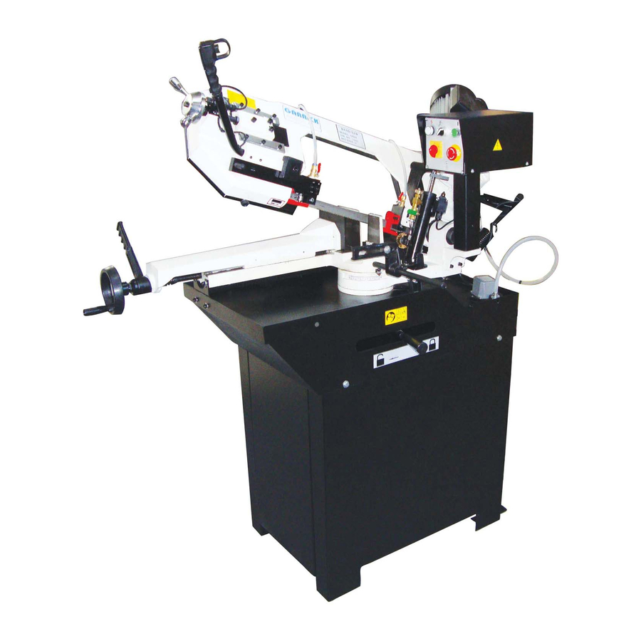
- Page 1 METAL CUTTING BAND SAW Model BS260 INSTRUCTION MANUAL For your safety, read all instructions carefully. ** This product carries the following approvals. CE, GS, CSA, and CU-L ISO-9001:2008 Certified...
-
Page 2: Table Of Contents
CONTENTS SECTION 1—DESCRIPTION AND MAIN FEATURES 1.1 Forward 1.2 Piece inventory 1.3 Machine description and use 1.4 Unintended use of the machine 1.5 Sound level 1.6 Technical characteristics SECTION 2—SAFETY REGULATIONS 2.1 Safety 2.2 Safety signs 2.3 Clothing 2.4 Ecology and pollution 2.5 Safe use SECTION 3—HANDLE AND INSTALLATION 3.1 Handling... -
Page 3: Section 1-Description And Main Features
SECTION 1 1.1.1 WHO SHOULD USE THIS MANUAL DESCRIPTION AND MAIN FEATURES This manual is the basic tool for the personnel involved in using the machine, whatever their duties: · operators involved in transporting and handling and handling 1.1 FOREWORD the machine. -
Page 4: Unintended Use Of The Machine
1.4 UNINTENDED USE OF THE MACHINE 1.6 TECHNICAL CHARACTERISTICS DANGER! Saw band size 2460 x 27 x 0.9 The operator must use the machine in accordance Two-speed motor 1400/700 50Hz with the guidelines set forth in this manual, 1400 50Hz One-speed motorr specifically the regulations in force relating to 1700 60Hz... -
Page 7: Section 2-Safety Regulations
SECTION 2 Concerned, if not correctly performed, may cause SAFETY REGULATIONS serious injuries, death or long term health risks. 2.1 SAFETY The user must provide instruction for the personnel involved in CAUTION! running the machine regarding accident hazards, the safety This sign warns that the operations concerned, if not devices provided for the operator and the general accident correctly performed, may result in damage to the... -
Page 8: Safety Signs
2.2 SAFETY SIGNS products used for cleaning and maintaining the machine. · Keep the labels and the instructions for the products The machine has been designed to incorporate all possible safety devices for the health and safety of the used; if fuel oils or other chemical substances are operators. - Page 9 · Should the machine exceed the acoustic pressure level kept under a suitable protective cap. If the floor is particularly slippery, wear non-slip shoes. of 85 dB, suitable protections such as headphones · Ensure the power supply system complies with the must be used to protect the hearing.
-
Page 10: Handling
SECTION 3 HANDLING AND INSTALLATION DANGER! 3.1 HANDLING The lifting and transporting operations can be extremely dangerous if not carried out with maximum caution. Move For long distance the machine may be transported on all unqualified personnel away from the area. Clean, clear lorries or train wagons. -
Page 11: Installation
· Reposition the machine with its base in its position then secure the base with the screws provided. If the machine is supplied without a base, then it must be secured by means of the two holes (15 Fig.1) to a special structure capable of supporting the weight of the machine and any unbalancing created when using WARNING! -
Page 12: General Controls
emulsifiable oil as directed by the manufacturer (normally approx. 10% oil). · Make sure that the quantity of coolant which is distributed during the cutting operation is sufficient. The blade must be well lubricated. · Before operating the machine, check its general efficiency and familiarize yourself with the control devices and their functions. -
Page 13: Before Use
· Push the Emergency (red mushroom) (6 Fig.1). SECTION 4 · Turn the total switch (8 Fig.1) to “OFF” (or position “0”). INSTRCTIONS FOR USE 4.1 BEFORE USE WARNING! Before starting up the machine the operator must read and assimilate this entire manual, particularly Section 2 which deals with safety. -
Page 14: Normal Cutting
6. Guard opening microswitch ( Fig.8 ) The machine is equipped with a position action microswitch. The function of this device is to stop the band from rotating if the FLYWHEEL GUARD opens ( 4 Fig.1). 7. Limit switch (25 Fig.1) When the cutting is completed, the band saw is stopped. -
Page 15: Vice Unit
4.8 ADJUSTING THE BAND TENSION For an optimum band tension adjustment operate as follows: · Turn the handwheel (23 fig.1) until the stop rests DANGER! This operation must be performed with the machine against the microswitch, located immediately below the handwheel support flange. (1 fig.7) off and voltage disconnected. -
Page 16: Adjusting The Bow Return Stroke
WARNING! Ensure the blade teeth rotate in the correct direction (see the arrow on the flywheel safety guard—Fig.6) · Tighten the band by means of the special handwheel (3 Fig.10); · Close the flywheel safety guard and secure it with the special clamps. -
Page 17: After Use
4.14 AFTER USE SECTION 5 MAINTENANCE After use all machining residues or other humid or dusty 5.1 MAINTENANCE materials must be cleaned from the machine. Keep the machine clean and in good condition. It will continue to give better results. WARNING! It is essential for all maintenance operations to be performed with the motor off and the machine... - Page 19 PART LIST Part Part Description Size No. Description Size No. Base (right part) Hand Wheel Set Screw M8 x 10 Hex. Cap Bolt M12 x40 Bearing Bushing Washer Thrust Ball Bearing #51104 Hex. Cap Bolt M8 x 16 Lock Handle Base Plate Bushing Base (left part)
- Page 20 PART LIST Part Part Description Size No. Description Size No. Emergency Switch Main Connect Switch Handle Power Indicator Light Hex. Socket Cap Screw M10 x 30 Hex. Socket Cap Screw M5 x 8 Spring Washer Washer Hex. Socket Cap Screw M5 x 8 Spring Washer Cover...
- Page 21 PART LIST Part Part Description Size No. Description Size No. Round Head Screw M4 x 8 Spring Washer Hex. Cap Bolt M8 x 30 Spring Washer Gear Box Hex. Cap Bolt M10 x 25 178-1 Vent Screw Spring Washer 178-2 Key 8 x 8 x 35 Washer Set Screw...
- Page 27 NOTES Page 27...
- Page 28 Distributed by: Garrick Herbert Pty Ltd KIRRAWEE NSW Australia. www.garrickherbert.com.au...
Need help?
Do you have a question about the BS260 and is the answer not in the manual?
Questions and answers