Advertisement
Quick Links
Application
Important: Use this System 450™ Series Reset
Control Modules with Real-Time Clock and Relay
Output only as an operating control. Where failure
or malfunction of the System 450 Series Control
Module could lead to personal injury or property
damage to the controlled equipment or other
property, additional precautions must be designed
into the control system. Incorporate and maintain
other devices, such as supervisory or alarm systems
or safety or limit controls, intended to warn of or
protect against failure or malfunction of the System
450 Series Control Module.
Important: Utiliser ce System 450 Series Reset
Control Modules with Real-Time Clock and
Relay Output uniquement en tant que dispositif
de régulation. Lorsqu'une défaillance ou un
dysfonctionnement du System 450 Series Control
Module risque de provoquer des blessures ou
d'endommager l'équipement contrôlé ou un
autre équipement, la conception du système de
contrôle doit intégrer des dispositifs de protection
supplémentaires. Veiller dans ce cas à intégrer de
façon permanente d'autres dispositifs, tels que
des systèmes de supervision ou d'alarme, ou des
dispositifs de sécurité ou de limitation, ayant une
fonction d'avertissement ou de protection en cas de
défaillance ou de dysfonctionnement du System 450
Series Control Module.
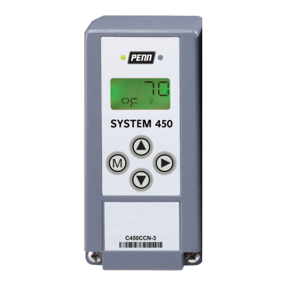
System 450 is a family of modular, digital electronic
controls that is easily assembled and set up to provide
reliable temperature, pressure, and humidity control for a
wide variety of HVACR and commercial/industrial process
applications.
The System 450 reset control modules allow you to
configure custom application-specific control systems
with reset control and/or real-time setback control for
temperature and humidity (only) control applications.
System 450 expansion modules allow you to control up to
10 outputs, which can be relay and analog outputs.
C450RxN-1 and C450RxN-3 Reset Control models are
Single-Pole, Double-Throw (SPDT) relay control modules
with temperature reset capability, real-time setback
capability, a Liquid Crystal Display (LCD), and a four-button
touch pad User Interface (UI) that allow you to set up
custom System 450 control systems.
The C450RBN-1 and C450RBN-3 model provide one SPDT
relay.
The C450RCN-1 and C450RCN-3 model provide two SPDT
relays.
Refer to the System 450 Series Modular Control Systems with
Reset Control Modules Technical Bulletin (LIT-12011842) for
more detailed information on designing, installing, setting
System 450 Series Reset Control Modules with
Real-Time Clock and Relay Output Installation
up, and troubleshooting System 450 Series components
and control systems.
Figure 1: System 450 Module dimensions, mm
Installation
Observe the following System 450 location guidelines:
• Ensure that the mounting surface can support the
module assembly, mounting hardware, and any (user-
supplied) panel or enclosure.
• Mount the modules upright and plugged together in
a horizontal row where possible (Figure 3). DIN rail
mounting is highly recommended.
• Mount modules on flat, even surfaces.
• Allow sufficient space for wires and connections.
• Mount the modules in locations free of corrosive vapors
and observe the ambient operating conditions in the
System 450 Series Reset Control Modules with Real-
Time Clock and Relay Output technical
• Do not mount the modules on surfaces that are prone
to vibration or in locations where radio frequency or
electromagnetic emissions may cause interference.
• Do not install the modules in airtight enclosures.
• Do not install heat-generating devices in an enclosure
with the modules that may cause the temperature to
exceed the ambient operating limit.
Guide
Part No. 24-7664-2888 Rev. E
2020-04-01
specifications.
C450RBN, C450RCN
Advertisement

Related Manuals for Penn System 450 C450RCN-1


Summary of Contents for Penn System 450 C450RCN-1
- Page 1 System 450 Series Reset Control Modules with Real-Time Clock and Relay Output Installation Guide Part No. 24-7664-2888 Rev. E 2020-04-01 Application up, and troubleshooting System 450 Series components and control systems. Important: Use this System 450™ Series Reset Figure 1: System 450 Module dimensions, mm Control Modules with Real-Time Clock and Relay Output only as an operating control.
- Page 2 Mounting WARNING Mount System 450 modules on 35 mm DIN rail (recommended) or directly to an even wall surface. See: Risk of Electric Shock • Mounting modules on DIN rail Disconnect or isolate all power supplies before mak- • Direct-mounting modules to wall surfaces ing electrical connections.
- Page 3 • When connecting System 450 compatible sensors See Figure 5 for the active/passive sensor jumper settings. with shielded cable to a System 450 control System 450 menu flow example. module, connect the cable shield drain lead to one of the C (common) terminals on the input sensor terminal block.
- Page 4 Figure 3: System 450 Reset Control System Example for a single boiler with a primary on/off boiler loop pump, variable speed secondary loop pump, and a heated water modulating supply valve. Note: In 120VAC applications, L1 must be the hot wire and L2 must be the neutral or common wire. Callout Description>...
-
Page 5: Setup And Adjustments
Table 1: System 450 terminal wiring information Label Terminal function Wire sizes LNC1, LNC2 Connects equipment control circuit to the normally closed contact on the SPDT relay. 0.08 mm to 2.5 mm 28 AWG to 14 AWG LNO1, LNO2 Connects equipment control circuit to the normally open contact on the SPDT relay. - Page 6 Temperature sensors are passive (2-wire) sensors and the - Do not change the module positions corresponding jumpers must be positioned across both after a System 450 control system is set pins. Humidity transducers are active (3-wire) sensors and up in the UI. System 450 control logic is corresponding jumpers must be positioned on one pin (or set up in the UI according to the Sensor removed completely).
- Page 7 current time and day is 11:32 A.M. on Tuesday, and the Output is set up with SP<EP and OSP<OEP; and Relay current calculated Reset Setpoint is 153°F. Output 2 has 17 hours of total runtime (relay ON). Figure 6: Main screens Figure 7: System Status screens Accessing the System 450 Setup screens...
- Page 8 Setting up System 450 Sensors You must set up the sensors (inputs) for your control system before you can set up any of the outputs. See Accessing the System 450 Setup screens. The following table provides information about System 450 compatible sensors for Reset Control Modules.
- Page 9 Setting up the System 450 Reset Figure 10: Sn-2 Sensor Type Selection screen Setpoint The System 450 Reset Control Modules feature temperature and humidity setpoint reset capability based Note: If your control system does not use on a Master temperature sensor (Sn-1) and a control loop three sensors, simply press Next while the two sensor (Sn-2).
- Page 10 Note: You must set up Sn-1 and Sn-2 before you Figure 15: Reset Setpoint Setup Start screen can set up a RSP for your reset control system. Sn-1 is always the Master temperature sensor; typically an outdoor air temperature sensor. Sn-2 is always the control loop sensor;...
- Page 11 Note: The relationship between RSTR and RENd In the Shutdown Low Temperature Selection (RSTR > RENd or RSTR < RENd) determines screen, press Up or Down to select the Shutdown whether an increase in temperature sensed Low Temperature value (sensed at the Master sensor at Sn-1 increases or decreases the RSP.
- Page 12 Setting up a Standard Relay Output In the Load Balancing Selection screen, press Up or Down to enable (ON) or disable (OFF) the Load A standard relay output provides On/Off control for your Balancing feature for your Reset Control system. When the System 450 Load Balancing feature is application based on a fixed setpoint sensor (Sn-1, Sn-2, enabled (ON), the control system uses the relay ON...
- Page 13 In the Relay ON Selection screen, press Up or The following figure shows 10 seconds selected Down to select the value at which the output relay for the minimum relay-off time for Relay Output turns On. Relay ON is defined as relay LED On, relay contacts LNO to LC are closed, and LNC to LC contacts are open.
- Page 14 If you do not need to change the output’s sensor, Figure 35: Relay Output Setup Start screen press Next in the Edit Sensor screen to save the current sensor selection, complete the output setup, and return to the Output Setup Start screen. To change the output’s sensor, press Up or Down in the Edit Sensor screen to select the In the Sensor Selection screen, press Up or Down to...
- Page 15 In the Offset from Reset Setpoint Selection screen, press Up or Down to select the Reset Setpoint Offset Figure 40: Minimum Relay OFF Time Selection screen value for the output. Select an OSET value to shift the (floating) Reset Setpoint (RSP) that the output references to a (floating) offset reset setpoint (RSP +OSET).
- Page 16 Setting up a standard Analog Output A standard analog output provides an analog signal to control your application based on a fixed setpoint sensor (Sn-1, Sn-2, or Sn-3). Analog outputs provide an auto-selecting analog signal that is proportional to the sensed input condition. The System 450 analog output senses the impedance of the controlled equipment’s analog input circuit and automatically delivers either a 0–10 VDC or 4–20 mA signal to the controlled equipment.
- Page 17 Table 5: System 450 Control Ramps, Analog Output control actions, and system setup value relationships Control ramp Control action Set the Analog Output value relationships for the desired displayed control action and corresponding control ramp SP < EP OSP > OEP In the Analog Output Setup Start screen, press Figure 46: Sensor Selection screens Next to go to the Sensor Selection screen.
- Page 18 In the Output Signal Strength at Setpoint Figure 51: Unoccupied Setback Selection screen Selection screen, press Up or Down to select the output’s %Output Signal Strength at Setpoint value. Select the strength of the signal that the output generates when the sensed condition is at the Setpoint value.
- Page 19 Note: If you change the sensor that an output In the Sensor Selection screen, press Up or Down to references, the default setup parameters and select the Reset Setpoint Sensor (rES) for the output values for the output change, and you must set to reference.
- Page 20 In the Integration Constant Selection screen, press - A positive offset value (OSET = +n) raises the Up or Down to select the Integration Constant for proportional band’s setpoint and end point the output. An integration constant allows you to set values.
- Page 21 Figure 64: Edit Sensor screen The following figure shows 12 hour clock format selected. Figure 67: 12 or 24 Hour Clock Selection screen 10. The Analog Output with Reset Setpoint is now set up in UI. Press M to scroll through the remaining Setup Start screens and continue setting up your control system, or press Up and Down simultaneously to In the Time of Day Setup screen, press Up or Down...
- Page 22 Figure 71: Example System 450 Reset Control weekly occupied/unoccupied setback schedule Relay Output that references an In the Occupied/Unoccupied Schedule Setup Input Sensor Start screen, press Next to go to the Day 1 (SUN) Occupied Time Selection screen. The Occupied/ System 450 menu flow example.
- Page 23 In the Day 1 Occupied Time Selection screen, - Occupied and Unoccupied time periods press Up or Down to select the time during Day 1 at are available at 15-minute intervals only. which the Occupied time begins (and the previous For example, 12:00 AM, 2:45 PM, 11:15 Unoccupied time ends).
- Page 24 Figure 77: Day 7 (SUN) Unoccupied Time Selection screen Figure 78: Occupied/Unoccupied Schedule Setup Start screen The Weekly Occupied/Unoccupied Schedule is now set up in the System 450 UI and you have returned to the Setup Start screen. Press M to scroll through the remaining Setup Start screens and continue setting up your control system, or press Up and Down simultaneously to return to the System 450...
- Page 25 System screens Description Relay output with RSP setup start screens. Boiler reset on or off. Relay output with RSP setup start screens. Boiler primary pump on or off. Analog output with RSP set up start screens. Secondary loop VFD speed. Standard analog output setup start screens.
- Page 26 System 450 Series Reset Control Modules with Real-Time Clock and Relay Output technical specifications Table 6: C450RxN-1 and C450RxN-3 System 450 Reset Control Modules technical specifications Specification Description Product C450RxN-1/C450RxN-3: System 450 Reset Control Module models are sensing controls and operating controls with LCD, four-button touch pad, and On/Off relay output.
-
Page 27: North American Emissions Compliance
North American emissions compliance United States This equipment has been tested and found to comply with the limits for a Class B digital device, pursuant to Part 15 of the FCC Rules. These limits are designed to provide reasonable protection against harmful interference in a residential installation. - Page 28 © 2020 Johnson Controls. All rights reserved. All specifications and other information shown were current as of document revision and are subject to change without notice. www.penncontrols.com...
Need help?
Do you have a question about the System 450 C450RCN-1 and is the answer not in the manual?
Questions and answers