Table of Contents
Advertisement
Quick Links
Applications
Important: The V246 Series 2-Way Pressure-
Actuated Water-Regulating Valves for High-Pressure
Refrigerants is intended to control coolant media
flow under normal operating conditions. Where
failure or malfunction of the V246 valve could
lead to personal injury or property damage to the
controlled equipment or other property, additional
precautions must be designed into the control
system. Incorporate and maintain other devices,
such as supervisory or alarm systems or safety or
limit controls, intended to warn of or protect against
failure or malfunction of the V246 valve.
Risk
This product is made of a copper alloy, which contains
lead. The product is therefore not to be used on drink-
ing water.
The V246 Series 2-Way Pressure-Actuated Water-
Regulating Valves for High-Pressure Refrigerants come
in two types of control action: direct acting and reverse
acting. V246 valves regulate water flow to control
refrigerant head pressure in systems with water-cooled
condensers.
The V246 Series Valves are available in 3/8 in. through 2
in. sizes and have a maximum allowable water pressure
of 150 psi (10.3 bar). Direct acting V246 valves have an
adjustable opening point in a refrigerant pressure range
of 200 to 400 psi (13.8 to 27.6 bar), and reverse acting
valves have a range of 135 to 300 psi (9.3 to 20.7 bar).
V246 valves may be used with standard non-corrosive
refrigerants.
Maritime models, which have nickel copper (Monel
internal parts, are available for applications where the
coolant may be corrosive to the internal parts.
V246 Series 2-Way Pressure-Actuated
Water-Regulating Valves for High-Pressure
Warning
Refrigerants Installation Guide
Installation
Risk of Environmental Damage
Provide proper containment for any potential release
of refrigerant, solvent, or oil. Such hazardous materials
can be harmful to the environment if they are released.
Important:
• If the V246 valve is installed on equipment that
contains hazardous or regulated materials
such as certain refrigerants or lubricants, you
must comply with all standards and regulations
governing the containment and handling of those
materials.
• After installing the V246 valve, evacuate pressure
connection lines to remove air, moisture, and
other contaminants in a manner consistent
with applicable environmental regulations and
standards.
• Take care to prevent foreign materials such as
weld slag, thread burrs, metal chips, and scale
from entering the piping system. This debris can
damage or severely impede the operation of the
valve by embedding itself in the seats, scoring the
valve, and ultimately resulting in seat leakage.
If the debris becomes embedded in the seats,
subsequent flushing and filtering of the piping
system with the valve installed does not remedy
the problem.
Install the valve vertically with the range adjustment
screw on the top, and the sensing element and pressure
connection line on the bottom, to allow oil and refrigerant
to drain away from the valve sensing element.
)
®
Mount the valve so that the valve sensing element is
above the refrigerant tap point, if possible. If it is not
possible to mount the bellows of the valve above the tap
point, loop the capillary above the tap point and below
the bellows and then connect to the valve. Tap off of the
topside of the high side line. This minimizes the effect of
refrigerant oil in the capillary on valve reaction time.
Do not mount the valve in any position other than vertical
unless specified by the manufacturer of the equipment
on which the valve is installed. Follow the manufacturer's
installation instructions.
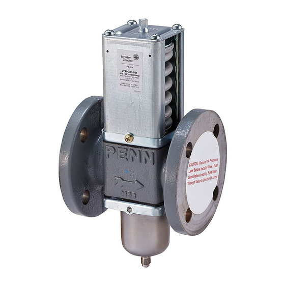
The direction of water flow is indicated by an arrow on the
valve body. See Figure 1.
Part No. 24-7664-2713 Rev. G
CAUTION
2019-06-20
V246
Advertisement
Table of Contents

Related Manuals for Penn V246 Series


Summary of Contents for Penn V246 Series
- Page 1 If the debris becomes embedded in the seats, The V246 Series Valves are available in 3/8 in. through 2 subsequent flushing and filtering of the piping in. sizes and have a maximum allowable water pressure system with the valve installed does not remedy of 150 psi (10.3 bar).
- Page 2 Table 2. To prevent refrigerant leakage, cause valve malfunction. V246 Series 2-Way Pressure-Actuated Water-Regulating Valves for High-Pressure Refrigerants Installation Guide...
- Page 3 Maritime/Navy STT14A-601R 3/8 in. Commercial STT14A-603R DPM14A-600R SEP93A-600R Low Flow Maritime/Navy Not Applicable 1/2 in. Commercial STT15A-602R DPM15A-602R SEP93A-601R Maritime/Navy STT15A-603R 3/4 in. Commercial STT16A-601R DPM16A-601R SEP93A-602R Maritime/Navy STT17A-613R V246 Series 2-Way Pressure-Actuated Water-Regulating Valves for High-Pressure Refrigerants Installation Guide...
- Page 4 Technical Specifications Table 5: V246 Series 2-Way Pressure-Actuated Water-Regulating Valves for High-Pressure Refrigerants Factory-Set Opening Point • Direct Acting 200 psi (13.8 bar) • Reverse Acting 165 psi (11.4 bar) Maximum Working Pressure 630 psi (43.4 bar) Opening Point Adjustment •...
Need help?
Do you have a question about the V246 Series and is the answer not in the manual?
Questions and answers