Table of Contents
Advertisement
Quick Links
Advertisement
Table of Contents

Subscribe to Our Youtube Channel
Related Manuals for LI-COR LI-840A


Summary of Contents for LI-COR LI-840A
- Page 1 LI-840A O GAS ANALYZER Instruction Manual...
- Page 3 LI-840A O Analyzer Instruction Manual...
- Page 4 Federal Communications Commission Radio Frequency Interference Statement WARNING: This equipment generates, uses, and can radiate radio frequency energy and if not installed in accordance with the instruction manual, may cause interference to radio communications. It has been tested and found to comply with the limits for a Class A computing device pursuant to Subpart J of Part 15 of FCC rules, which are designed to provide a reasonable pro- tection against such interference when operated in a commercial environment. ...
- Page 5 This document is serial number specific. May 21, 2013 Page 1 of 1 Adherence to the EMC testing standards listed above is claimed for the non-OEM version of the LI-840A. EMC performance can be affected by the complete installation, therefore if using OEM versions (LI-840- 01 and LI-840A-02), the final equipment manufacturer should re-qualify the complete system to the EMC Directive.
- Page 6 NOTICE The information contained in this document is subject to change without notice. LI-COR MAKES NO WARRANTY OF ANY KIND WITH REGARD TO THIS MATERIAL, INCLUDING, BUT NOT LIMITED TO THE IMPLIED WARRANTIES OF MERCHANTABILITY AND FITNESS FOR A PARTICULAR PURPOSE. LI-COR shall not be liable for errors contained herein or for incidental or consequential damages in connection with the furnishing, performance, or use of this material.
-
Page 7: Table Of Contents
Table of Contents Section 1. General Description What's What Features Precautions Getting Started Tutorial Section 2. Power On Alarms Section 3. Operation Installing the PC Communication Software on Your Computer Setting the Communication Parameters Cabling RS-232 Output Initial Setup... - Page 8 Using the Toolbar Settings Window - Setting Operational Parameters Enable Heater Pressure Compensation Filter DAC Output CO2 Span Range 3-13 Alarms 3-13 Using the Terminal Strip 3-14 Software Reference 3-16 Charting Window 3-16 Series 1 3-17 Series 2 3-17 X-Axis Max 3-17 Diagnostic Window 3-18...
- Page 9 Considerations for performing a secondary span 3-28 Coefficients Page 3-29 Advanced Page 3-30 Connecting the LI-840A to the LI-1400 Datalogger 3-32 Section 4. Theory of Operation System Overview Optical Bench System Section 5. Maintenance Cleaning the Optical Bench Changing the Fuse...
- Page 10 Appendix B. Equation Summary Appendix C. Pin Assignments Appendix D. Suppliers Appendix E. Configuration Grammar Element Descriptions E-15...
-
Page 11: Section 1. General Description
Section 1. General Description What's What This procedure should be followed if you have just taken delivery of your LI-840A. Check the packing list to verify that you have received everything that was ordered and that you have also received the following items: RS-232 Cable - (Part #392-04993), used to connect the LI-840A to your computer. - Page 12 Section 1 Standard Spare Parts Kit (9980-021) - This kit contains replacement parts for the LI-840A. As you become familiar with the analyzer you will learn which items to keep close at hand and which items can be stored away. The spare parts kit contains these items: Description Qty.
-
Page 13: Features
The LI-840A is an economical, high performance, non-dispersive infrared gas analyzer designed to be used for a wide variety of applications. Some of the LI-840A's important features include: A 14 cm (5.5") optical bench is used to obtain a CO measurement range of 0-20,000 ppm (parts per million, or µmol/mol) and an H... -
Page 14: Getting Started Tutorial
Many of these steps are described in greater detail throughout this manual. Install the PC Communications Software. This software is used to set the zero and span of the LI-840A and set up data communication and data transfer parameters for viewing and logging data. Installation instructions can be found in Installing the PC Communication Software on Your Computer on page 3-1. - Page 15 Connect a power source to the LI-840A The LI-840A requires an input voltage of 12-30 VDC. The power supply must be able to source a maximum current drain of 1.2A (at 12 VDC). After the instrument has warmed up it will draw about 0.3A (at 12 VDC) with the heaters on.
- Page 16 Connect the RS-232 cable. Connect one end of the serial cable to the 9-pin Serial I/O port on the LI-840A front panel, and the other end to a serial port on your computer. If you want to interface to a device with a 25-pin serial port, a 9-pin to 25-pin adapter must be used;...
- Page 17 Quick Connect ‘Y’ NOTE: More information about plumbing options and parts available from LI-COR can be found in Application Note #IRG4-105, entitled ‘Air Pumps and Accessories for LI-COR Gas Ana- lyzers - Suggested Parts and Vendors’, which can be downloaded from www.licor.- com/env/support.
- Page 18 LI-840A. IMPORTANT: Always install the external air filter before operating the LI-840A. Insert filter into the input airstream before it enters the LI-840A. Failure to do this will lead to con- tamination of the optical path.
- Page 19 Click on the program icon to start the application. The window appears. Select Main Connect from the File menu. Choose the serial port to which the LI-840A is connected, and the data out- put interval. Click the button. If the analyzer is connected properly, data will appear in Connect the main window.
- Page 20 Section 1 Set the analyzer zero. NOTE: The LI-840A is calibrated at the factory before shipping. It is recommended, however, that you verify the calibration by connecting a gas with known concentration and reading the displayed value. If the instrument needs to be calibrated, follow the steps below.
- Page 21 Section 1 Set the analyzer span. Connect a span gas with known concentration of CO to the input air stream. Choose a span gas that will be below or close to the highest reading expected. Select the tab. Enter the Span value of the span gas in ppm.
- Page 22 Section 1 Set up the logging parameters. Select from the Logging menu. Choose the File Header(s) to be output with the data, Options the values to be logged, the field delimiter, and log frequency. Click . Choose from the Start Logging menu. Enter a file name for the data file. Click Save Set up the charting parameters, if desired.
-
Page 23: Section 2. Power On
10.5 volts, the analyzer will not power up, and the Low Battery LED on the top panel will illuminate. The LI-840A will continue to operate with a low battery; there will, however, be a cor- responding reduction in performance. - Page 24 Section 2 Figure 2-1. Location of alarm jumpers LK1 and LK2. Section 2. Power On...
- Page 25 Section 2 Open Drain Logic (Digital, 0-5V) Figure 2-2. Position of jumpers for open drain and 0-5V output. Section 2. Power On...
- Page 26 Section 2 In addition, a "dead band" value can be set in software for both high and low alarms. To under- stand how the alarms and dead band values work, look at the diagram below. High Alarm activated 1000 High Alarm = 1000 Dead Band = 100 ppm High Alarm deactivated Low Alarm...
- Page 27 Section 3) can help reduce fluctuations in readings. Alarm LEDs can be viewed on the top panel of the LI-840A. Terminals 3 and 5 on the terminal strip are also connected to the High and Low alarms, respectively. This is useful for connecting...
- Page 28 Section 2 Air Inlet LI-840 1 2 3 Mains 120VAC Exhaust Input 3 - 30V 12VDC Output A list of suppliers of electronic relay switches can be found in Appendix D. NOTE: Consult your local electrical codes before wiring, and/or have a professional elec- trician wire your application.
-
Page 29: Section 3. Operation
Section 3. Operation This section describes basic operation of the LI-840A. Installing the PC Communication Software on Your Computer The software application is shipped on CD. It requires that your computer have an RS-232 serial (COM) interface, and Windows® 7, 8, 8.1, or 10. -
Page 30: Setting The Communication Parameters
The serial cable (null modem) included has 9-pin connectors on both ends; either end plugs into the 9-pin connector (Serial I/O) on the front panel of the LI-840A. Use this cable to inter- face with your computer's 9-pin serial port. If you want to interface to a computer with a 25-pin serial port, a 9-pin to 25-pin adapter must be used. -
Page 31: Initial Setup
File menu, or click on the connect icon on the toolbar, beneath the File Connect menu. You are asked to select the serial port to which the LI-840A is connected, and the output interval at which data are output (0.5 to 20 seconds, in 0.5 second increments). - Page 32 O concentration (°C or mmol/- mol), cell temperature and pressure, and the status of various LI-840A parameters. There are also three menus used to configure the LI-840A, perform zero and span calibrations, and set up the parameters for recording data.
- Page 33 H2O in ppt off. Alternatively, you can click on the H O units being displayed in the Main window to change the display. The LI-840A parameters displayed in the Main window are as follows: Parameter Description Cell Temperature Temperature (°C) in the LI-840A optical cell. This value should remain near 50 °C when the heater is turned ON.
-
Page 34: Using The Toolbar
Section 3 Parameter Description Filter Shows the current value for software signal averaging, set in the Set- tings window. The filter can be set from 0 (no signal averaging) to 20 seconds. DAC Output Displays source channels for DAC1 and DAC2, and the voltage out- put range (0-2.5V or 0-5V). -
Page 35: Settings Window - Setting Operational Parameters
Section 3 Settings Window - Setting Operational Parameters The Settings window contains parameters related to initial setup of the LI-840A, including signal filtering, high and low alarm setup, heater and pressure compensation options, and DAC output sources. Choose from the View menu (or click on the toolbar icon) to open the Settings... -
Page 36: Enable Heater
Section 3 Enable Heater The Heater should be enabled to maintain the optical bench at a constant 50 °C. Pressure Compensation Enable the Pressure Compensation check box to automatically correct gas concentration values for changes in cell pressure. In most cases this should be turned on; disabling this feature means that no pressure correction is desired in the gas concentration calculations, which can lead to erroneous measurements. - Page 37 Voltage output is measured by attaching the positive lead from the logging device to terminal 9 (V Out 1), or terminal 7 (V Out 2) on the LI-840A terminal strip. Connect the negative lead to position 10 (GND), or position 8 (GND).
- Page 38 Section 3 Example: The DAC output range selected is 0-5V (V ), the zero CO value entered is 1000 ppm (X ), the full scale CO value entered is 2000 ppm (X ), and the measured output voltage (V) is 2.9V. To calculate the CO concentration from 3-1 above, = 1580 ppm.
- Page 39 Section 3 Example: The DAC output range selected is 0-5V (V ), the zero H O value entered is 10 mmol/mol (X ), the full scale H O value entered is 60 mmol/mol (X ), and the measured out- put voltage (V) is 2.9V. To calculate the H O concentration from equation 3-4 above, = 39.0 mmol/mol.
- Page 40 Section 3 where V is the measured voltage, X is the full scale value for cell pressure output (entered in the Settings Window as the 2.5 or 5V value, up to 115 kPa), X is the zero value entered, and Vmax is the full scale DAC output voltage selected (5V or 2.5V).
-
Page 41: Co2 Span Range
The span range entry field determines the maximum CO range over which the LI-840A will make measurements. The factory calibration range for the LI-840A is 0-20,000 ppm. Note that there is a benefit to selecting a narrower range if that range is adequate for your experiment. The narrower range provides better resolution in terms of the digital-to-analog converter (DAC). -
Page 42: Using The Terminal Strip
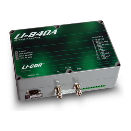
Section 3 Using the Terminal Strip The terminal strip is located on the front panel of the LI-840A. To connect the wires, insert the bare wire end into the appropriate terminal and tighten the screw above that terminal using the small flat head screwdriver in the spare parts kit. - Page 43 Section 3 Terminal Label Description 4-20 mA 2 Current output channel 2 Ground 4-20 mA 1 Current output channel 1 Ground Section 3. Operation 3-15...
-
Page 44: Software Reference
Section 3 Software Reference Charting Window Select from the View menu to open the Charting window (below). This is the window Charting in which you can set up the parameters for plotting your data. Two charts can be plotted sim- ultaneously, using Y axes on either side of the chart. -
Page 45: Series 1
Section 3 Series 1 The Series 1 options are used to plot a chart with the Y axis on the left side of the chart. Choose the value to be logged and set the maximum and minimum values for the Y axis. Series 2 The Series 2 options are used to plot a chart with the Y axis on the right side of the chart. -
Page 46: Diagnostic Window
Section 3 Diagnostic Window Select from the View menu to open the Diagnostics window (below). This window Diagnostics displays the current LI-840A internal software version number, the input voltage, and raw absorp- tion values. 3-18 Section 3. Operation... -
Page 47: Logging Data
Section 3 Logging Data Start Logging Opens the Log File Destination dialog, where you enter a file name for the data file. The file extension .txt is added automatically. Section 3. Operation 3-19... -
Page 48: Stop Logging
Section 3 Stop Logging Stops data logging. Pause Logging Pauses logging of data until is chosen from the Logging menu again, or the Start button Start on the toolbar is pressed. 3-20 Section 3. Operation... -
Page 49: Options
Section 3 Options Opens the Logging Options window, where you can configure the data output options. Section 3. Operation 3-21... - Page 50 Section 3 As configured above, the data output would appear similar to that shown below. 3-22 Section 3. Operation...
-
Page 51: User Calibration - Setting The Zero And Span
Section 3 User Calibration - Setting the Zero and Span Select from the View menu to open the Calibration window. This is the area in Calibration which you set the zero and spans of the LI-840A. Section 3. Operation 3-23... - Page 52 It is recommended that you perform the zero calibrations first, followed by the span calibrations. To zero, flow a dry, CO -free gas through the LI-840A and make sure the optical cell is com- pletely purged. Press the button under the Zero tab.
- Page 53 The span will be set electronically, and the current date will be entered in the "Last span performed on:" field when completed. Note: Ensure that the CO standards are accurate, as this will determine the overall accuracy of the LI-840A. Section 3. Operation 3-25...
-
Page 54: Two Point Span (Span 2 Tab)
Section 3 Repeat for the H O channel using an airstream of known dew point. Note: Purge the cell with the O span gas for up to 15 minutes before spanning H O. The LI-610 Portable Dew Point Generator is capable of providing an airstream with a known water vapor concentration. - Page 55 Section 3 In the LI-840A version 2.0 and above, the span value is a linear function of absorptance, and thus has two parameters, a slope and an offset (see Equation Summary on page B-1). Normal span setting adjusts the offset and leaves the slope alone. Setting the secondary span adjusts the slope, then adjusts the offset value for the new slope value.
-
Page 56: Considerations For Performing A Secondary Span
(e.g. 200 and 20000, or 300 and 1500, etc.). “Far apart” means in absorptance, not concentration. We recommend absorptance differences of at least 0.1 when choosing concentrations for setting span and secondary span. Typical LI-840A 1000 10000... -
Page 57: Coefficients Page
OK to do as many consecutive secondary spans at various concentrations as you’d like. Coefficients Page The LI-840A uses a double rectangular hyperbola for the CO calibration, and a third order poly- nomial for H O calibration. -
Page 58: Advanced Page
Section 3 coefficients, as well as those for band broadening and cross sensitivity, and coefficients for the internal pressure transducer. These coefficients are fixed at the factory. The calibration coefficients are unique to each instrument, and may be found on the calibration sheet shipped from the factory. - Page 59 PC. If new constants are entered in this window, click to send the values to the Send Constants LI-840A for implementation. In most cases you should not change the values in this window; see Symbol Summary on page B- 11 for a description of the terms used in this window.
-
Page 60: Connecting The Li-840A To The Li-1400 Datalogger
Section 3 Connecting the LI-840A to the LI-1400 Datalogger The following example shows how you can connect the LI-840A to a datalogging device such as the LI-COR Model LI-1400 DataLogger to collect analog data and convert to meaningful CO and/or H O values. - Page 61 Section 3 This general equation can be converted into simple multipliers, based on the two available voltage output ranges and the CO (maximum 20,000 ppm) or H O (maximum 100% RH) range. These can be any value, depending on what is chose for the 0V and the full scale 2.5V and 5V DAC output values.
- Page 62 Access to the voltage channels requires the 1400-301 Terminal block. Voltage channels are des- ignated by the letter “V” and sequentially numbered V1-4. The lead from LI-840A terminal #7 or #9 should be attached to one of the LI-1400 terminals labeled V1, V2, V3, or V4, while the lead from terminal #8 or #10 should be attached to one of the LI-1400 terminals labeled ↓(ground).
- Page 63 Section 3 Set the voltage output of the LI-840A for 2.5V output and specify the zero and maximum values for CO as described in DAC Output on page 3-8. In the LI-1400, configure V1 channel as General for CO Enter a description, such as CO Set Math = Poly(nomial) and press Ent(er).
- Page 64 Section 3 To log CO automatically: Set Log Routine to the desired log routine. Set Calc=Mean. To capture the minimum and maximum CO values, set MinMax accordingly. TCoef has no effect when Calc=Mean. It is used only when integrating. 3-36 Section 3.
-
Page 65: Section 4. Theory Of Operation
Section 4. Theory of Operation System Overview The LI-840A CO O Gas Analyzer is an absolute, non-dispersive, infrared (NDIR) gas analyzer based upon a single path, dual wavelength, infrared detection system. The CO and H O meas- urements are a function of the absorption of IR energy as it travels through the optical path. -
Page 66: Optical Bench System
Optical Bench System The LI-840A CO O Gas Analyzer optical path is a thermostatically controlled IR detection system. The optical bench operation is based upon a broad band IR source and a pyroelectric detector. - Page 67 Optical Path Detector Source Broad Band IR Source O Filters Thermistor Thermistor 2.35 & 2.59 µm Gas Outlet Gas Inlet Heating Element Heating Element Ribbon Cable Connector Figure 4-1. Schematic diagram of the LI-840A optical bench. Section 4. Theory of Operation...
- Page 68 Section 4 The optical bench has a thermostat that maintains a constant operating temperature of 50 °C. A feedback loop is used to regulate the optical bench temperature. As shown in Figure 4-1, two thermistors, located in the source and detector housings, measure the present temperature. The thermistors are monitored as part of the control loop to determine corrections necessary in the thermal balance.
- Page 69 Section 4 Another key parameter in the concentration calculation is the gas temperature in the optical path. It is assumed in the analyzer operation that the gas temperature will equilibrate to the optical bench temperature (50 °C) by the time it enters the optical path. Since the instrument performs temperature and pressure corrections as part of the concentration calculation, this assumption is very important.
- Page 70 Section 4 Section 4. Theory of Operation...
-
Page 71: Section 5. Maintenance
Follow these steps to clean the optical bench: Turn the LI-840A off. Remove the six screws on the LI-840A top panel and remove the cover. Note that these screws are not molded into the case and may fall out. - Page 72 Section 5 Detector Source Optical Bench Hose Barb Ribbon Cable Bev-a-line Tubing Connector There are four screws on the source and detector circuit boards that must be removed. Section 5. Maintenance...
- Page 73 Section 5 Remove the four screws in the corners of the boards. Do not remove the four small screws. The source and detector housings (with attached circuit boards) can now be removed. The Remove these bench will appear as shown below. It is a good practice to replace the O-rings when cleaning or 4 screws replacing the optical path.
- Page 74 Re-assemble the bench, making sure the O-rings are in place on both ends of the bench. Note that the orientation of the cylinder is not important; either end can be inserted into the source or detector housing. Re-assemble the LI-840A case. Optical Reflector Make sure that the foam insulation on the inside top cover is positioned over the optical bench;...
-
Page 75: Changing The Fuse
If the battery fails to power the LI-840A, and will not light the Power LED on the top panel, check to see if the fuse has blown. To check the fuse, remove the six screws on the top of the LI-840A. The fuse is located on the main circuit board, near the port, as shown below. -
Page 76: Note On Infrared Source Replacement
Section 5 Note on Infrared Source Replacement The infrared source in the LI-840A is rated for more than 18,000 hours of life. Should the source fail, a replacement can be obtained from LI-COR Biosciences. The source can be replaced in the field;... -
Page 77: Storing The Li-840A
Section 5 Storing the LI-840A The LI-840A can be stored in non-condensing conditions, but if it is exposed to high humidity or moderate humidity for a long period of time while it is powered off, the humidity can tem- porarily affect measurements. You can identify this issue by observing unexpected drift that sta- bilizes after several days of operation, an offset in measurements, or unresponsiveness. - Page 78 Section 5 Section 5. Maintenance...
-
Page 79: Appendix A. Specifications
Appendix A. Specifications Measurement Range: 0-20,000 ppm Accuracy: Better than 1.5% of reading Calibration Drift Zero Drift: <0.15 ppm/°C Span Drift: < 0.03 %/°C Total Drift at 370 ppm: <0.4 ppm/°C RMS Noise at 370 ppm with 1 sec signal filtering: <1 ppm Sensitivity to water vapor: <... - Page 80 Appendix A Span Drift at 10 mmol/mol: <0.006 mmol/mol/°C Total Drift at 10 mmol/mol: <0.016 mmol/mol/°C RMS Noise at 10 mmol/mol with 1 sec signal filtering: <0.01 mmol/mol Sensitivity to CO : <0.0001 mmol/mol H O/ppm CO Measurement Principle: Non-Dispersive Infrared Traceability: Traceable gases to WMO standards for CO .
- Page 81 Appendix B. Equation Summary The LI-840A computes CO and H O concentrations using an equation of the form where c is concentration, f() is the calibration function, α is the absorptance, g (α,P) is the pres- sure correction, S(α) is the span, and T is the temperature (°C) of the gas in the cell, typically 51.5 °C.
- Page 82 Appendix B O Equations Absorptance α for water vapor is computed from where V and V are the sample and reference raw detector readings and Z is the zero para- meter. The pressure correction for water vapor is an empirical function g () of absorptance and pressure P: The value of P...
- Page 83 Appendix B Equations The measurement of CO is a bit more complicated than for H O because of the influence of water vapor. There is a slight direct cross sensitivity in the CO signal to H O. This is measured at the factory and accounted for in the computation of absorptance (equation B-8).
- Page 84 Appendix B where a = 1.10158, b = -6.1217 * 10 , c = -0.266278, d = 3.69895, and z is the asymptotic value of absorptance, obtained from the calibration coefficients (equation B-13). B-10 When P > P B-11 where X, A, and B are computed as in equation B-9. The variable g () is viewable on the dia- gnostics window (see Operation on page 3-1).
- Page 85 Appendix B B-12 where f (x) is a function whose inverse is a double rectangular hyperbola, and whose coefficients (a1…a4) are given on the calibration sheet. B-13 Solving equation B-13 for C yields the calibration function B-14 Where B-15 ψ (W) accounts for band broadening by water vapor, and is viewable on the Diagnostic window. B-16 Appendix B.
- Page 86 Appendix B The band broadening coefficient h(α ) has been determined to be 1.45 for the LI-840A for CO concentrations near ambient. At higher concentrations, the value decreases. We capture this behavior with an empirical relationship (equation B-17). B-17 Where z is from equation B-10, and b is the low concentration band broadening coefficient: 1.45. ...
- Page 87 Appendix B Implementation Note: We formulated B-17 with 0.64b – 0.64 instead of the simple equivalent (0.29) because this allows band broadening corrections to be turned off by setting b to 1. When =1, h(α ) = 1 everywhere. Also, to avoid computational problems (underflows, overflows, and division by zero) we constrain the argument α...
- Page 88 Appendix B Calibration Equations Zeroing H When the command for zeroing water is received, the LI-840A computes the water zero from equation B-19, where are averaged for 5 seconds. B-19 Zeroing CO When the command for zeroing CO is received, the LI-840A computes the CO...
- Page 89 Appendix B B-21 where B-22 The instrument retains the following values, which are used for subsequent secondary spans: B-23 B-24 Secondary Span H When the secondary span command for H O is received, the instrument computes new values for both S and S .
- Page 90 Appendix B Spanning CO When the command for setting the span for CO is received, along with the target concentration , the LI-840A computes S from equation B-26, where are averaged for 5 seconds. B-26 where B-27 Note that B-28...
- Page 91 Given the new span slope S , update the span offset S by equation B-26. Symbol Summary Many of the quantities described in the above section are available from the LI-840A. These are summarized in Table B-1 below. Table B-1. Symbol summary Symbol XML Tag: <LI840>+...
- Page 92 Appendix B Table B-1. Symbol summary (...continued) Symbol XML Tag: <LI840>+ Description <AUXdata><pHA> Pressure corrected absorptance of H (α <data><h2o> O (mmol mol <data><cellpress> Pressure (kPa) <data><celltemp> Temp (C) <data><co2abs absorptance α (α <AUXdata><pcA> Pressure corrected absorptance of CO <data><co2> (µmol mol <data><raw><h2o>...
- Page 93 Appendix B Table B-1. Symbol summary (...continued) Symbol XML Tag: <LI840>+ Description <cal><co2kzero> Zero and Span values <cal><co2kspan> <cal><co2kspan2> <poly><xs> Cross sensitivity coefficient <poly><bb> Band broadening coefficient for low CO h(α <AUXdata><bb_EFF> Computed band broadening coeff for the current absorptance ѱ(W) <AUXdata><psi>...
- Page 95 Appendix C. Pin Assignments The figure below indicates pin assignments for the DB-9 connector. Data (RXD) Data (TXD) Signal Ground (SG) Appendix C. Pin Assignments ...
- Page 97 Appendix D. Suppliers Although the LI-840A has no internal chemicals to replace, the following suppliers may be use- ful for obtaining chemicals for generating a chemical zero gas. The company names, addresses, and phone numbers are the most current we have at the time of this printing. In some cases the information may change without notice.
- Page 98 Appendix D Fisher Scientific www.fishersci.com 711 Forbes Avenue Soda Lime: Part #S201-212 Pittsburgh, PA 15219-4785 (LI-COR Part #9960-071) Phone: 201-467-6400 Mg(ClO : Part #M54-500 (500g) FAX: 201-379-7415 Toll free: 800-776-7000 Toll free FAX: 800-926-1166 Thomas Scientific www.thomassci.com P.O. Box 99 Soda Lime: Part #C703-B76 Swedesboro, NJ ...
- Page 99 Appendix D Ascarite II GFS Chemicals Thomas Scientific www.gfschemicals.com www.thomassci.com P.O. Box 245 P.O. Box 99 Powell, OH 3065 Swedesboro, NJ 08085-6099 Phone: 614-881-5501 Phone: 609-467-2000 FAX: 614-881-5989 FAX: 609-467-3087 Toll free: 800-858-9682 Toll free: 800-345-2100 Toll free FAX: 800-345-5232 P.W.
- Page 100 Appendix D Electronic Relay Switches Crydom Inc. Potter & Brumfield Products Div. 9525 Chesapeake Dr. Siemens Electromechanical Components, Inc. San Diego, CA 92123 200 S. Richland Creek Dr. 800-827-9366 Princeton, IN 47671-0001 FAX: 619-715-7280 info@ae.sec.siemens.com Appendix D. Suppliers ...
- Page 101 LI-840A Communications and XML The configuration grammar used to communicate with the LI-840A is based upon a subset of the eXtensible Markup Language (XML). XML relies on the use of tags to "Markup", or give structural rules to a set of data.
- Page 102 <NAME> data. All elements combined make up the XML document. Connecting and Configuring Data Output The LI-840A communicates through a serial port on the front of the instrument. This port is configured as follows: Baud Rate: 9600 bps Data Bits: 8...
- Page 103 After a serial connection is established, the LI-840A will immediately send data out the serial port in the manner in which it was configured previously. In order to reconfigure the LI-840A to output specific data values, you must send the RS-232 portion of the XML grammar to the instrument with the desired values "turned on". ...
- Page 104 Appendix E Sending Data to the LI-840A To send data to the LI-840A, each string must end with a '\n' to ensure that the LI-840A can parse consecutive commands. After data have been sent to the LI-840A, the instrument replies with: <LI840><ACK>TRUE</ACK></LI840>...
- Page 105 Polling the Current State of the LI-840A The LI-840A can be polled for individual sets of data by sending an XML document with a '?' in place of the set of elements requested. The element sets that can be requested include the data set, the current configuration, and the entire state of the instrument.
- Page 106 </CAL> </LI840> An acknowledgement is returned from the LI-840A if the command was accepted. <LI840><ACK>TRUE</ACK></LI840> After a few seconds, all of the calibration information is returned from the LI-840A, indicating that it has finished the zero and/or span. <LI840> <CAL>...
- Page 107 Appendix E <CO2KSPAN2>{float}</CO2KSPAN2> </CAL> </LI840> If the calibration cannot be performed, an ERROR is sent: <LI840><ERROR>{Error Text}</ERROR></LI840>. To Zero the LI-840A Send the XML command to initiate the zero. <LI840> <CAL> <DATE>YYYY-MM-DD</DATE> <CO2ZERO>TRUE</CO2ZERO> </CAL> </LI840> Wait for the acknowledgment. Wait for the date to be returned to verify the zero operation succeeded. If the operation fails an will be sent.
- Page 108 Appendix E To Span the LI-840A Send the XML command to initiate the span. <LI840> <CAL> <DATE>YYYY-MM-DD</DATE> <CO2SPAN>Gas Concentration</CO2SPAN> </CAL> </LI840> Wait for the acknowledgement. Wait for the date to be returned to verify the span operation succeeded. If the operation fails an <ERROR>...
- Page 109 Wait for the date to be returned to verify the span operation succeeded. If the operation fails an will be sent. <ERROR> LI-840A XML Grammar and Element Description Data Types in the XML Grammar {val | val |...} The value will be a member of the specified set. | = or.
- Page 110 Appendix E Boolean values, TRUE | FALSE. {float} Floating point values in decimal or exponential notation. {int} Integers. {iso date} A date in the ISO format. 4 digit year - 2 digit month - 2 digit day. Example: 2002-04-27. XML Grammar <LI840>...
- Page 111 Appendix E <CO2REF>{int}</CO2REF> <H2O>{int}</H2O> <H2OREF>{int}</H2OREF> </RAW> </DATA> <AUXDATA> <PCA>{float}</PCA> <PHA>{float}</PHA> <BB_EFF>{float}</BB_EFF> <PSI>{float}</PSI> </AUXDATA> <RS232> <CO2>{bool}</CO2> <H2O>{float}</H2O> <CELLTEMP>{bool}</CELLTEMP> <CELLPRES>{bool}</CELLPRES> <IVOLT>{bool}</IVOLT> <CO2ABS>{bool}</CO2ABS> <H2OABS>{bool}</H2OABS> <H2ODEWPOINT>{bool}</H2ODEWPOINT> <RAW> <CO2>{bool}</CO2> <CO2REF>{bool}</CO2REF> <H2O>{bool}</H2O> <H2OREF>{bool}</H2OREF> </RAW> <ECHO>{bool}</ECHO> <STRIP>{bool}</STRIP> </RS232> Appendix E. Configuration Grammar E-11...
- Page 112 Appendix E <CFG> <HEATER>{bool}</HEATER> <PCOMP>{bool}</PCOMP> <FILTER>{int}</FILTER> <OUTRATE>{float}</OUTRATE> <ALARMS> <SOURCE>H2O | CO2<SOURCE> <ENABLED>{bool}</ENABLED> <HIGH>{float}</HIGH> <HDEAD>{float}</HDEAD> <LOW>{float}</LOW> <LDEAD>{float}</LDEAD> </ALARMS> <BENCH>{5|14}</BENCH> <SPAN>{int}</SPAN> <DACS> <RANGE>{2.5|5.0}</RANGE> <SET1>{float}</SET1> <SET2>{float}</SET2> <D1>{NONE|CO2|H2O|H2ODP|CELLTEMP|CELLPRES}</D1> <D1_0>{float}</D1_0> <D1_F>{float}</D1_F> <D2>{NONE|CO2|H2O|H2ODP|CELLTEMP|CELLPRES}</D2> <D2_0>{float}</D2_0> <D2_0>{float}</D2_F> </DACS> </CFG> <CAL> <DATE>{serial number and iso date}</DATE> E-12 Appendix E. Configuration Grammar ...
- Page 113 Appendix E <CO2ZERO>{bool}</CO2ZERO> <CO2SPAN>{int}</CO2SPAN> <co2span2>{int}</co2span2> <H2OZERO>{bool}</H2OZERO> <H2OSPAN>{int}</H2OSPAN> <H2OSPAN2>{int}</H2OSPAN2> <CO2KZERO>{float}</CO2KZERO> <CO2KSPAN>{float}</CO2KSPAN> <co2kspan2>{float}</co2span2> <H2OZERO>{float}</H2OZERO> <H2OKSPAN>{float}</H2OKSPAN> <h2okspan2>{float}</h2ospan2> <CO2LASTZERO>{iso date}</CO2LASTZERO> <CO2LASTSPAN>{iso date}</CO2LASTSPAN> <H2OLASTZERO>{iso date}</H2OLASTZERO> <H2OLASTSPAN>{iso date}</H2OLASTSPAN> </CAL> <POLY> <DATE>{string}</DATE> <BB>{float}</BB> <XS>{float}</XS> <RESET>{bool}</RESET> <CO2> <A1>{float}</A1> <A2>{float}</A2> <A3>{float}</A3> Appendix E. Configuration Grammar E-13...
- Page 114 Appendix E <A4>{float}</A4> </CO2> <H2O> <A1>{float}</A1> <A2>{float}</A2> <A3>{float}</A3> </H2O> <PRESS> <A0>{float}</A0> <A1>{float}</A1> </PRESS> </POLY> <ERROR>{string}</ERROR> </LI840> E-14 Appendix E. Configuration Grammar ...
- Page 115 Appendix E Element Descriptions Parent Value(s) R/W Comments <LI840> N/A (root) <ACK> <LI840> is the root tag for all XML statements. <VER> A ? outputs the entire XML document. <ERROR> <DATA> <AUXDATA> <RS232> <CFG> <CAL> <POLY> Examples: <LI840>?</LI840> <LI840><ACK>TRUE</ACK></LI840> Appendix E. Configuration Grammar E-15...
- Page 116 Parent Value(s) R/W Comments <DATA> <LI840> <CO2> <DATA> contains all data values sent from <CO2ABS> the LI-840A. All of the elements within the <H2O> DATA tag are readable only. A ? requests all <H2ODEWPOINT> data values to be output. <H2OABS>...
- Page 117 Appendix E Parent Value(s) Comments <CO2> <DATA> Float in ppm <CO2ABS> <DATA> Float absorption <H O> <DATA> Float O in mmol/mol <H2ODEWPOINT> <DATA> Float O in °C <H2OABS> <DATA> Float O absorption <CELLTEMP> <DATA> Float Cell temperature <CELLPRES> <DATA> Float Cell pressure <IVOLT>...
- Page 118 Value(s) R/W Comments <AUXDATA> <LI840> ? <AUXDATA> contains all auxiliary data values that can be retrieved from the LI-840A. All of the elements witin the AUXDATA tag are readable only. A ? requests all data values to be output. E-18...
- Page 119 Appendix E Parent Value(s) Comments <PCA> <AUXDATA> Float <PHA> <AUXDATA> Float <PSI> <AUXDATA> Float <BB_EFF> <AUXDATA> Float Parent Value(s) R/W Comments <RS232> <LI840> <CO2> Setting <RS232> values will determine <CO2ABS> what values are output in <DATA> <H2O><H2ODEWPOINT> <H2OABS> <CELLTEMP> <CELLPRES> <IVOLT>...
- Page 120 Appendix E Parent Value(s) Comments <CO2> <RS232> TRUE | FALSE in ppm <CO2ABS> <RS232> TRUE | FALSE absorption <H2O> <RS232> TRUE | FALSE O in mmol/mol <H2ODEWPOINT> <RS232> TRUE | FALSE O dew point <H2OABS> <RS232> TRUE | FALSE O absorption <CELLTEMP>...
- Page 121 Appendix E Parent Value(s) Comments <CO2> <RAW> Integer <CO2REF> <RAW> Integer <H2O> <RAW> Integer <H2OREF> <RAW> Integer Appendix E. Configuration Grammar E-21...
- Page 122 Appendix E Parent Value(s) R/W Comments <CFG> <LI840> <OUTRATE> Elements within the <CFG> tag control system set- <HEATER> tings. <PCOMP> <DOFFSET> <FILTER> <ALARMS> <DACS> <BENCH> <SPAN> Example: <LI840><CFG><HEATER>TRUE</HEATER><PCOMP>TRUE</PCOMP></CFG></LI840> E-22 Appendix E. Configuration Grammar ...
- Page 123 Appendix E Parent Value(s) Comments <OUTRATE> <CFG> 0.5 to 20 Output data every N seconds (0.5 s increments). <HEATER> <CFG> TRUE | FALSE Turn heater on/off. <PCOMP> <CFG> TRUE | FALSE Pressure compensation on/off. <FILTER> <CFG> 0 to 20 Set a 0 to 20 second filter. <ALARMS>...
- Page 124 Appendix E Parent Value(s) R/W Comments <ENABLED> <ALARMS> TRUE | FALSE R/W Enable alarms. <SOURCE> <ALARMS> CO2 | H2O R/W Channel (CO :ppm, H O:mmol/mol) <HIGH> <ALARMS> Float R/W High alarm on at this value. <HDEAD> <ALARMS> Float R/W High alarm off at this value. <LOW>...
- Page 125 Appendix E Parent Value(s) R/W Comments <RANGE> <DACS> 2.5 | 5.0 Output voltage. 2.5V or 5.0V. <SET1> <DACS> Float Set DAC output to value (DACS must be NONE) <SET2> <DACS> Float Set DAC output to value (DACS must be NONE) <D1>...
- Page 126 Appendix E <LI840><CFG><DACS><RANGE>2.5</RANGE><D1>CO2</D1><D2>CELLTEMP</D2></DACS> </CFG></LI840> E-26 Appendix E. Configuration Grammar ...
- Page 127 Appendix E Parent Value(s) R/W Comments <CAL> <LI840> <DATE> Calibration parameters. When calibrating, <H2OZERO> <DATE> must be paired with a <CO2ZERO> <H2OSPAN> or a <CO2SPAN>, or a <H2OZERO> or <H2OSPAN2> <H2OSPAN>. <H2OLASTZERO> <H2OLASTSPAN> <H2OLASTSPAN2> <H2OKZERO> <H2OKSPAN> <H2OKSPAN2> <CO2ZERO> <CO2SPAN> <CO2SPAN2> <CO2LASTZERO>...
- Page 128 °C) <H2OSPAN2> <CAL> Float (H Start the second H O span. °C) <H2OLASTZERO> <CAL> 20 character Date the LI-840A was last zeroed. date <H2OLASTSPAN> <CAL> 20 character Date the LI-840A was last spanned. date <H2OKZERO> <CAL> Float R/W Calibration constant.
- Page 129 R/W Comments <CO2SPAN2> <CAL> Float (CO Start the second CO span. ppm) <CO2LASTZERO> <CAL> 20 character The date the LI-840A was last zeroed. date <CO2LASTSPAN> <CAL> 20 character The date the LI-840A was last spanned. date <CO2KZERO> <CAL> Float R/W Calibration constant.
- Page 130 Appendix E Examples: To Zero: <LI840><CAL><DATE>2015-02-07</DATE><CO2ZERO>TRUE</CO2ZERO></CAL></LI840> To Span: <LI840><CAL><DATE>2015-02-07</DATE><CO2SPAN>1000</CO2SPAN></CAL></LI840> Possible LI-840 Replies: <LI840><ACK>TRUE</ACK></LI840> <LI840><ERROR>{ErrorText}</ERROR></LI840> <LI840><CAL><CO2LASTSPAN>{isodate}</CO2LASTSPAN><CO2LASTZERO>{isod- ate}</CO2LASTZERO><CO2KZERO>{float} </CO2KZERO><CO2KSPAN>{float}</CO2KSPAN></CAL></LI840> Parent Value(s) R/W Comments <LI840> <POLY> 20 character date R/W Serial number and factory cal- ibration date:HGA XXXX Day Month Year <BB> <POLY> Float R/W Band broadening value.
- Page 131 Appendix E Parent Value(s) R/W Comments <CO2> <POLY> <A1><A2><A3><A4> R/W Floating point coefficients for the calibration inverse rectangular hyperbola. <H2O> <POLY> <A1><A2><A3> R/W Floating point coefficients for the O calibration polynomial. <PRESS> <POLY> <A0> R/W Floating point coefficient for CO pressure correction <A1>...
- Page 133 The defects are called to the attention of LI-COR, Inc. in Lincoln, Nebraska, in writing within one year after the shipping date of the instrument.
- Page 134 No-charge repair parts may be sent at LI-COR, Inc.'s sole discretion to the purchaser for install- ation by purchaser. LI-COR, Inc.'s liability is limited to repair or replace any part of the instrument without charge if LI-COR, Inc.'s examination disclosed that part to have been defective in material or work- manship.
- Page 135 To the extent not superseded by the terms of any extended warranty, the terms and conditions of LI-COR’s Warranty still apply. DISTRIBUTOR or the DISTRIBUTOR's customers may ship the instruments directly to LI-COR if they are unable to repair the instrument themselves even though the DISTRIBUTOR has been approved for making such repairs and has agreed with the customer to make such repairs as covered by this limited warranty.
- Page 138 ® Measuring Change in a Changing World LI-COR, Inc. • Environmental • 4647 Superior Street • P.O. Box 4425 • Lincoln, Nebraska 68504 USA Phone: 402-467-3576 • FAX: 402-467-2819 Toll-free 1-800-447-3576 (U.S. & Canada) envsales@licor.com www.licor.com...
Need help?
Do you have a question about the LI-840A and is the answer not in the manual?
Questions and answers