LI-COR LI-8100A Instruction Manual
Automated soil co2 fluxsystem & li
Hide thumbs
Also See for LI-8100A:
- Setup manual (37 pages) ,
- Quick start manual (2 pages) ,
- Instruction manual (64 pages)
Table of Contents
Advertisement
Advertisement
Table of Contents

Related Manuals for LI-COR LI-8100A


Summary of Contents for LI-COR LI-8100A
- Page 1 Automated Soil Flux System & LI-8150 Multiplexer Instruction Manual...
- Page 2 LI-8100A Automated Soil CO Flux System & LI-8150 Multiplexer Instruction Manual ®...
- Page 3 LI-COR MAKES NO WARRANTY OF ANY KIND WITH REGARD TO THIS MATERIAL, INCLUDING, BUT NOT LIMITED TO THE IMPLIED WARRANTIES OF MERCHANTABILITY AND FITNESS FOR A PARTICULAR PURPOSE. LI-COR shall not be liable for errors contained herein or for incidental or consequential damages in connection with the furnishing, performance, or use of this material.
- Page 4 Note on Safety LI-COR products have been designed to be safe when operated in the manner described in this manual. The safety of this product can not be guaranteed if the product is used in any other way than is specified in this manual.
-
Page 5: Declaration Of Conformity
Lincoln, Nebraska USA 68504 declares that the product Product Name: Automated Soil CO Flux System Model Number(s): LI-8100, LI-8100A Product Options: Survey Chamber, Long-Term Chamber conforms to the following Product Specifications: FCC CFR Part 15.109 Radiated Emissions, Class A IEC 61326 : 1997/A2:2001 Radiated Emissions, Class A... -
Page 6: Table Of Contents
Cable Connections ..........................2-1 The Analyzer Control Unit ......................... 2-3 Using Batteries ..........................2-3 Using PCMCIA (PC) Adapter Cards..................... 2-3 About LI-8100A Data Records and Storage Options ..............2-4 Using a Wireless Card ......................... 2-5 Air Filters............................2-5 Power On............................2-6 Automatic Restart Function ...................... - Page 7 Placement of Soil Temperature and Moisture Probes ..............2-21 References ............................2-22 Section 3. Measurement Quick Start About LI-8100A Data Files ........................ 3-7 Section 4. Theory of Operation Measuring Carbon Dioxide Flux from the Soil.................. 4-1 Deriving the Flux Equation: The Model .................... 4-2 Calculating the Flux from Measured Data..................
- Page 8 Connecting the Chamber to the Analyzer Control Unit ..............6-5 Making Measurements ........................6-6 Software Setup Using the LI-8100A Windows Application Software......... 6-7 Software Setup Using the LI-8100A Apple iOS Software ............6-15 Section 7. Using the Long-Term Chambers General Description ........................... 7-1 Changing the 8100-104/C Chamber Open Position..............
- Page 9 About ............................8-43 Section 9. Apple iOS Software Reference (Single-Chamber Mode) About Wireless Communication ....................... 9-1 Wireless Network Cards for the LI-8100A..................9-1 Handheld Requirements for Wireless or Serial Communication ............9-1 Handheld Software Requirements ....................9-2 Accessing On-line Help ......................9-2 The Setup Menu ..........................
- Page 10 Instrument Settings........................9-27 Auxiliary Inputs.......................... 9-29 Outputs ............................9-30 The Help Menu ..........................9-34 Indicators ........................... 9-34 About LI-8100A ......................... 9-35 Section 10. Using the LI-8150 Multiplexer About the LI-8150 ..........................10-1 What’s What ............................10-2 Cable/Hose Assembly ........................10-2 Spare Parts Kit ..........................10-2 Optional Accessories..........................10-2...
- Page 11 Setup Menu ............................10-35 Measurement Configuration...................... 10-35 Port Setup:Chamber ........................10-35 Port Setup:Observation ......................10-38 Port Setup:Data Logging......................10-41 Port Setup:V2 (V3, V4) ......................10-42 Port Sequence..........................10-44 Repeat............................10-45 Port Tools........................... 10-46 Presets............................10-48 Start Measurement........................10-49 View Menu ............................10-50 Instrument Status ........................
- Page 12 The 8100 Menu ..........................10-107 Instrument Settings........................10-107 Auxiliary Inputs........................10-108 Outputs ............................ 10-110 The Help Menu ..........................10-113 Indicators ..........................10-113 About LI-8100A ........................10-114 LI-8150 Maintenance and Repair ....................10-115 Fuses............................10-115 Tubing ............................10-115 Air Filters..........................10-115 Solenoid Valves ........................10-116 Section 11.
- Page 13 Changing the 8100-104/8100-104C Chamber Bowls..............12-47 Appendix A. Specifications Appendix B. Pin Assignments Appendix C. Glossary of Terms Appendix D. Equation Summary: Final Variables Warranty...
-
Page 14: Section 1. Getting Started
(FV8100) is also included to allow further examination and/or recomputation of your data. What's What If you have just taken delivery of your LI-8100A check the packing list to verify that you received everything ordered, including the following items:... -
Page 15: Analyzer Control Unit
Getting Started Analyzer Control Unit The Analyzer Control Unit is the yellow enclosure that houses the LI-8100A electronics and infrared gas analyzer. The interior of the Control Unit contains the indicator panel, brackets for the optional 6400-03 Rechargeable Battery, and an access panel for inserting or removing the wireless and compact flash cards. -
Page 16: Ethernet Cable
Getting Started A Serial-to-USB Adapter (p/n 6400-27) is provided to facilitate data transfer between the LI-8100A and computers lacking an RS-232 connector. Note that this does not convert the RS-232 serial connection into a USB connection. It simply allows the USB port to receive data via a standard RS-232 serial connection. -
Page 17: Software Cd
Attach shoulder strap here Software CD (p/n 8100-501) Contains the LI-8100A Windows® and interface software for Apple iOS, the LI-8100A Data Analysis (File Viewer) software, this instruction manual, the Data Analysis and PDA/LI-8100A Configuration manuals in PDF format. Application Software V2.0.0 Run Setup.exe... -
Page 18: Spare Parts Kit
Additional spares kits are packaged with their respective soil chambers, as well. An optional bellows kit (p/n 8100-623) is also available from LI-COR that can be used to replace damaged bellows on either the 10 cm or 20 cm Survey Chambers. - Page 19 Getting Started Description LI-COR Part No. 8100-621 8100-102 Survey Chamber Spares Kit Cable Ties 218-08499 Bev-a-line Tubing 222-01824 Thumb Nut 165-00140 10 cm Soil Collars 6581-157 8100-631 8100-103 Survey Chamber Spares Kit Cable Ties 218-08499 Bev-a-line Tubing 222-01824 Thumb Nut...
-
Page 20: Calibration Sheet
Bellows, 3" I.D. x 4.25" O.D. 254-7219 Calibration Sheet This data sheet is a copy of the calibration information entered into the LI-8100A by LI-COR. Keep it in a safe place for future reference. LI-COR also retains copies of calibration information for your soil CO flux system;... -
Page 21: Li-6020 Battery Charger
Getting Started NOTE: There are 2 battery connectors in the case; you can attach a second, fully charged battery before removing the discharged battery to provide uninterrupted operation. LI-6020 Battery Charger (115/230VAC) The LI-6020 can charge up to four 6400-03 batteries at a time. Soil Temperature Probes (p/n 8100-201, 8150-203, and 8100-203) The 8100-201 Omega soil temperature probe is a T-handled Type E thermocouple with 6.4 mm (0.25") diameter and 250 mm (10") immersion length. -
Page 22: 8100-104 And 8100-104C Upgrade Kits
Micro Case (p/n 8100-571). 8100-405 CO Mapping Kit The 8100-405 is an accessory for use with the LI-8100A Automated Soil CO Flux System, that allows spatial data (latitude, longitude, speed, direction) to be integrated with observations of soil CO flux or CO concentration. -
Page 23: Section 2. Initial Setup
Initial Setup Cable Connections There is a panel for connecting the RS-232, chamber, and Auxiliary Sensor Interface cables on the left side of the Analyzer Control Unit. The panel appears as shown in Figure 2-1 below. AUX. SENSOR AIR OUT AIR IN CHAMBER RS-232... - Page 24 Initial Setup Note that the fittings on the side panel have fine threads. Make sure there is no debris on the fittings before attaching the connectors, as the threads can be easily damaged. Cover the connectors with the attached connector dust caps whenever the connectors are not being used.
-
Page 25: The Analyzer Control Unit
The Analyzer Control Unit Using Batteries The LI-8100A requires one 6400-03 battery to power the instrument; alternatively, an external power source (10.5-28 VDC) can be connected via the Auxiliary Sensor Interface. The 6400-03 fits inside the Analyzer Control Unit, and can be connected to either of the two battery connectors. -
Page 26: About Li-8100A Data Records And Storage Options
PC card. About LI-8100A Data Records and Storage Options The LI-8100A has 18 Megabytes of onboard flash available for data collection. The data stored in onboard flash is compressed at an approximate ratio of 3:1. -
Page 27: Using A Wireless Card
Ethernet adapter card or Compact Flash card. The wireless card included is the only card warranted for use with the LI-8100A; while other cards could be used, LI-COR cannot guarantee the integrity of the data. Separate instructions for wireless networking with a PDA are included with the LI-8100A;... -
Page 28: Power On
Instructions for replacing the air filters are given in Section 12, Maintenance. Power On When the LI-8100A is powered on using the ON/OFF button on the indicator panel inside the Analyzer Control Unit, a series of LEDs will light. LOW BATTERY... -
Page 29: Automatic Restart Function
Figure 2-6. Keypad jumper position. Figure 2-7. Aux In jumper position. IMPORTANT: When the jumper is in the Aux In position, the LI-8100A presents a potential shock hazard. For example, if power is interrupted and the unit shuts off, it is possible to remove the access panel and make contact with electrical components;... - Page 30 Analyzer Control Unit. If you want the LI-8100A to restart the current measurement following a power interruption, reposition the jumper to the Aux In position as described above, and enable the Auto Restart function in software;...
-
Page 31: Using The Auxiliary Sensor Interface
Sensors can be powered externally or by the LI-8100A with a constant 5 VDC source. The Auxiliary Sensor Interface also has a 12-28 VDC input (3A minimum) for use with external power. -
Page 32: Auxiliary Sensor Interface Terminals
2-10 Initial Setup Figure 2-10. Auxiliary Sensor Interface and connector. Auxiliary Sensor Interface Terminals Loosen the 4 philips head screws in each corner of the Auxiliary Sensor Interface module and remove the top cover. The interior of the interface appears as shown below. - Page 33 2-11 Initial Setup V IN V OUT V OUT 10.5-28VDC 5VDC 5VDC 3A MAX 30mA 30mA SWITCHED Figure 2-12. Graphical representation of terminal positions. The terminal positions are numbered and configured as follows, reading left to right: Terminal Label Description V1 + Voltage input 1 positive V1 GND...
-
Page 34: Connecting Sensors To The Auxiliary Sensor Interface
2-12 Initial Setup Terminal Label Description V IN + Voltage input positive V IN - Voltage input negative V OUT + 5 VDC output positive V OUT - 5 VDC output negative V OUT + 5 VDC output positive (switched) V OUT - 5 VDC output negative (switched) Connecting Sensors to the Auxiliary Sensor Interface... - Page 35 2-13 Initial Setup Pull lightly on the wires to remove excess wire from inside the interface, re-attach the interface top cover, and tighten the gland cap. When you have finished installing all of your sensors and/or a power supply, attach the Auxiliary Sensor Interface cable connector to the connector on the side panel of the Analyzer Control Unit labeled Aux.
- Page 36 2-14 Initial Setup There are 10 EPDM type plugs that can be inserted into unused glands on the Auxiliary Sensor Interface; the plugs prevent water, insects, dirt, etc. from entering the interface box. Remove the top cover and insert the narrow end of the plug through the back of the gland and tighten the cap(s) (below).
-
Page 37: Connecting Soil Moisture/Temperature Probes To The Auxiliary Sensor Interface
2-15 Initial Setup Connecting Soil Moisture/Temperature Probes to the Auxiliary Sensor Interface The 8100-201 Omega Soil Temperature Probe (Omega Engineering Inc., Stamford, CT) is a 10” (25.4 cm) thermocouple probe terminated with two bare wires for connection to the Auxiliary Sensor Interface. Thermocouple channels 1-4 (T1-T4) can be used with the Omega soil temperature probe;... - Page 38 Soil Temperature Thermistor Probe; the Probe Adapter contains a resistor that allows the 8150-203 Soil Temperature Thermistor Probe to be used with the Auxiliary Sensor Interface on the LI-8100A Automated Soil CO Flux System. The 8100-203 is terminated with bare wires for connection to the Auxiliary Sensor Interface;...
- Page 39 2-17 Initial Setup The 8100-204 Theta Probe has four bare wire leads for connection to the Auxiliary Sensor Interface. Voltage channels 1-4 (V1-V4) can be used with the ECH O soil moisture probe; the soil probe must be set up in software. The 4-wire adapter cable has red, blue, yellow and green wires that are connected to V OUT 5VDC SWITCHED(+),V OUT 5VDC SWITCHED(-), V4(+), and V4(-) respectively, as shown in Figure 2-16.
-
Page 40: Important Note On Wire Insertion
Cut a section approximately 8.9 cm (3.5”) long or longer, depending on your soil type and experiment. Bevel one edge with a grinding wheel so that it is easier to press into the soil. The 10 cm (4") soil collars are available from LI-COR under part #6581-157 (1 each). -
Page 41: Installing And Using Soil Collars
2-19 Initial Setup 3.9" min I.D./4.5" max O.D. 8.4" O.D. (9.9 to 11.4 cm) (21.34 cm) 4.5" ± 0.125" (11.43 cm) 3.5" (8.9 cm) 24° Figure 2-17. Dimensions for 10 cm (4") and 20.3 cm (8") soil collars. Installing and Using Soil Collars Soil collars should be installed several hours to one day before making a measurement. -
Page 42: Measuring The Chamber Offset
2-20 Initial Setup Measuring the Chamber Offset The chamber offset is used to determine the volume of air inside the soil collar, which is in turn used to calculate the total system volume. The total system volume is an important part of the flux calculation, so it should be determined as accurately as possible. -
Page 43: Placement Of Soil Temperature And Moisture Probes
2-21 Initial Setup and then subtract the distance between the upper edge of the chamber base plate and the top of the soil collar to obtain the offset value. This value should be as close to 1 cm as possible, since the default Long-Term chamber volume value in the software accounts for displacement by the collar. -
Page 44: References
2-22 Initial Setup References Norman, J.M., R.L. Garcia and S.B. Verma. 1992. Soil surface CO fluxes and the carbon budget of a grassland. J. Geophys. Res. 97(D17):18845-18853. Hanson, P.J., S.D. Wullschleger, S.A. Bohlman and D.E. Todd. 1993. Seasonal and topographical patterns of forest floor CO efflux from an upland oak forest. - Page 45 Start This section is designed to quickly demonstrate a simple LI-8100A measurement. For the purposes of this discussion we will refer to the use of the LI-8100A Windows application software. Follow these steps to complete this tutorial: Connect the chamber cables, battery, and computer as described in Section 2, Initial Setup.
-
Page 46: Section 3. Measurement Quick Start
Measurement Quick Start Observe the Status of the IRGA on the Main window of the LI-8100A software, or the LED of the LI-8100A keypad. After about 10 minutes, the IRGA Ready LED will illuminate, and the Status in the Main window will show "IRGA: READY". - Page 47 Custom – a user-built chamber, or tubing used for profiling studies. Long Term – LI-COR p/n 8100-101 Long Term – LI-COR p/n 8100-104 Long Term – LI-COR p/n 8100-104C 10 cm Survey – LI-COR p/n 8100-102 20 cm Survey – LI-COR p/n 8100-103...
- Page 48 Measurement Quick Start The Chamber Volume and Soil Area values are automatically entered. Enter a value for the Chamber Offset. The Chamber Offset is the distance (in cm) between the soil surface and the bottom of the soil chamber, and is dependent upon the depth that the collar is inserted into the ground (discussed in Section 2, Initial Setup).
- Page 49 Measurement Quick Start Enter a name for the instrument at "Instrument Name" (ACU401 in the example above). The instrument name is sent to the LI-8100A, where it is saved and becomes part of the data record. Click Apply. Click OK.
- Page 50 Measurement Quick Start Enter a File Name, and Comments if desired. Data can be logged to the LI-8100A internal flash memory, or to a Compact Flash Card (CF), if one is installed. 11. Click Start Measurement. The dialog box will close. As the chamber automatically closes, observe the progress of the measurement in the Main window.
-
Page 51: About Li-8100A Data Files
About LI-8100A Data Files An LI-8100A data file consists of lines of tab-delimited text with one or more Observations. An Observation is preceded by Header information, and also contains Raw Records, Summary Records, and Footer information as shown... - Page 52 Summary Records Footer Header - The lines from "LI-8100A" through the labels line. Type - The first item in each record is called the Type, and it identifies the type of record. The types are -1, 1, 2, 3, and 4.
- Page 53 Type 2 value of the Cdry column, and “Range Etime” means the Type 4 value of the Etime column. The table below lists the LI-8100A variables, including the Label that appears in the Header information, and a description of the variable. A summary of the method...
- Page 54 The type of record Pre-purge Wait time between observations Observation Length Original observation length Flow8100 Pump setting in LI-8100A Analyzer Control Unit FlowMux Pump setting in the LI-8150 Multiplexer Tmux Multiplexer temperature at start of observation Virga IRGA volume, in cm...
- Page 55 Number of iterations used in the Exponential Fit Exp_MaxIter Maximum number of iterations allowed for the Exponential Fit. This is fixed to 10 in the LI-8100A (but can be ajusted in the FV8100 program) Lin Flux Flux computed from Linear Fit...
-
Page 56: Section 4. Theory Of Operation
CO movement in the soil. The LI-8100A uses the rate of increase of CO in a measurement chamber to estimate the rate at which CO diffuses into free air outside the chamber. -
Page 57: Deriving The Flux Equation: The Model
Theory of Operation Soil CO flux varies substantially in both space and time. The LI-8100A can be used to sample both types of variability. The Survey chamber allows rapid measurements to be made at many sites, and the Long Term chamber supports automated, sequential measurements at a single site over time. - Page 58 Theory of Operation The mass balance equations for CO , water vapor and air take the form storage = flux in - flux out. We neglect the effects of leaks for now, but we will consider them later. Mass Balance = sf O Mass Balance = sf...
- Page 59 ), as well as the initial values for w and c '/ t. After the chamber closes, the LI-8100A performs a linear regression with time on the first 10 values of each measured variable. The initial values of p, T and w are obtained from the time zero intercepts of these regressions;...
-
Page 60: Calculating The Flux From Measured Data
( ) 0 − ∂ Calculating the Flux from Measured Data In the LI-8100A, equations (4-7), (4-10) and (4-11) are implemented in a form that presents the variables in more familiar and intuitive units. Equation (4-7) is computed as 10VP... - Page 61 Theory of Operation Figure 4-2 shows C'(t) vs t data that were obtained from a soil CO flux measurement with two observations. The data are marked to show when the chamber closed and when it opened. Chamber Chamber Chamber closed opens closed Chamber...
- Page 62 Theory of Operation asymptote, all in μmol CO /mol air (ppm); a is a parameter that defines the curvature of the fit (s The initial value of C'(t), called C ' in equation (4-13), is computed from the intercept of a linear regression of the first 10 points after the chamber closes. This is used as a parameter in the non-linear regression that fits equation (4-12) to the C'(t) vs t data between the end of the Dead Band and the end of the observation.
-
Page 63: Relationship Between The Model Equation (4-10) And Empirical Equation (4-13)
CO efflux rate reported by the LI-8100A in Type 3 records are computed by this method. We recommend you use these only for comparison to the initial values, which are... -
Page 64: Concentrations
10s to 60s, with 30s being a good value to use as a first estimate. Dead bands and observation times can be adjusted after the fact, using the LI-8100A Data Analysis software (FV8100). This program allows you to recalculate data easily, using subsets of data selected to give optimal dead bands and observation lengths. - Page 65 Table 4-1. Definitions of the variables used in the derivations and implemented in the LI-8100A. Variable Description (units) LI-8100A Data File Column Total Volume (m "Vtotal" Total Volume (cm Total Surface Area (m "Area"...
-
Page 66: Using The 8100-104C For Net Carbon Exchange (Nce)
4-11 Theory of Operation Initial value of W Type 1 "H2O" Rate constant (s Air flow rate out of the chamber (mol s mole fraction of air outside the chamber (mol mol Dilution-corrected CO mole fraction of air in the soil (mol Dilution-corrected CO mole fraction of air inside the chamber... - Page 67 4-12 Theory of Operation respiration, including above ground respiration and soil respiration. It is a key variable for understanding the carbon balance of an ecosystem. NCE can be readily measured with the eddy covariance method over a large uniform field or with the chamber-based method for short and small canopies.
- Page 68 4-26 Equation 4-25 is exactly the same as Equation 4-10 for opaque chambers. For the LI-8100A, we use a generic exponential equation to fit the time series of chamber concentration. For a clear chamber, when C’ , net carbon uptake is <...
-
Page 69: Shading Effects
Figure 4-4. Example of time series of C ’ from one observation from the clear chamber over a short grassland on the LI-COR campus. Values for various fitted parameters ( t , and N ) from Equation 4-26 are also shown. The observation length was 120 s with a deadband of 20 s. -
Page 70: Measuring Par With The 8100-104C
Measuring PAR with the 8100-104C Measurements of Photosynthetically Active Radiation (PAR) for use with the 8100-104C can be made with the LI-COR LI-190 Quantum Sensor. A Leveling Stake (p/n 8100-604, pictured below) is available for mounting the LI-190 and inserting into the ground near the chamber. Because the LI-190... -
Page 71: References
4-16 Theory of Operation References Healy, R.W., R.G. Striegle, T.F. Russell, G.L. Hutchinson, G.P. Livingston. 1996. Numerical evaluation of static-chamber measurements of soil-atmosphere gas exchange: Identification of physical processes. Soil Sci. Soc. Am. J. 60:740-747. Morison, J.I.L., 1987. Intercellular CO concentration and stomatal response to . -
Page 72: Section 5. User Calibration
LI-8100A is used. The majority of the analyzer drift is corrected by setting the zero, so this should be the highest priority. It is also a good idea to verify analyzer performance by periodically checking the span. -
Page 73: Co And H O Gas Standards
The LI-610 Portable Dew Point Generator can be used to provide air with a known dew point for the primary calibration of new analyzers. The span of the analyzer in the LI-8100A is stable when the zero is set on a regular basis, and soil CO flux measurements are not very sensitive to errors in the water vapor measurement. -
Page 74: H 2 O Span
For known water vapor concentrations, a convenient standard to use is a dew point generator such as the LI-COR LI-610 Portable Dew Point Generator. To avoid condensation problems, choose a dew point temperature that is about 3 to 5 °C below the ambient temperature. -
Page 75: Using Chemical Scrubbers
Fill each tube with the proper chemical. Ensure that air flows freely through the tube. 2. Verify that the LI-8100A pump is turned on. 3. Plumb the LI-8100A. A. Attach a chemical tube containing either Soda Lime or Drierite to the air inlet. -
Page 76: Setting The Span: H 2 O
1. Verify that the LI-8100A pump is turned on. 2. Plumb the LI-8100A. A. Connect the output of the LI-610 to the air inlet on the LI-8100A, using a "Y" fitting. B. Connect a short piece of tubing (a few inches) to the other end of the "Y"... -
Page 77: Two Point Span (Span 2 Tab)
The optical bench in the LI-8100A uses a span value that is a linear function of absorptance, with two parameters; a slope and an offset. The normal span function adjusts the offset and leaves the slope alone. - Page 78 10000 100000 (ppm) Figure 5-1. CO absorptance differences for typical LI-8100A optical bench. For CO , the difference in absorptance between 200 and 1000 ppm is typically about 0.1. There is also a 0.1 absorptance difference between 3500 and 7000 ppm, and between 15,000 and 40,000 ppm.
- Page 79 A. Monitor the CO and/or H O concentrations in the main window of the LI-8100A Windows interface software. When the concentration is stable proceed to the calibration window. B. Select Calibration from the Utilities menu. C. Click on the Span 2 tab.
-
Page 80: General Description
The larger size of the 8100-103 allows the chamber to be placed on the 20 cm soil collars used with the LI-8100A Long-Term Chambers. This allows for measurements of spatial variability on the same soil collars as are used for temporal measurements, using a large exposed soil area. - Page 81 Using the 10 and 20 cm Survey Chambers Pressure Vent Bellows Air In Bellows Port Air Out Chamber Survey Collar Gasket (p/n 6581-065) Soil Collar Figure 6-1. The 8100-102 10 cm Survey Chamber.
- Page 82 Using the 10 and 20 cm Survey Chambers Pressure Vent Manifold Chamber Gasket (p/n 224-07606) Soil Collar Gasket (p/n 6581-108) Foam Seal Gasket (p/n 6581-107) Figure 6-2. The 8100-103 20 cm Survey Chamber.
-
Page 83: The Measurement Flow Path
Using the 10 and 20 cm Survey Chambers The Measurement Flow Path Air flow generated by a diaphragm pump inside the Analyzer Control Unit provides a steady flow of air to the Survey Chamber, with minimal pulsations. Air flow to the chamber provides mixing without using fans that can cause pressure gradients. -
Page 84: Connecting The Chamber To The Analyzer Control Unit
Using the 10 and 20 cm Survey Chambers Diaphragm Pump Analyzer Control Unit Chamber Filter Vent Bellows Valve Valve Pressure Transducer Figure 6-4. The bellows flow path to the Survey Chambers. Connecting the Chamber to the Analyzer Control Unit There are three hoses connected to the Survey Chambers; air to the chamber, air returning from the chamber to the Analyzer Control Unit, and air that drives the bellows. -
Page 85: Making Measurements
Connect the LI-8100A to your computer using the appropriate serial cable, as described in Section 2, Initial Setup. Turn the LI-8100A on using the ON/OFF button on the inside panel of the Analyzer Control Unit. Wait for the IRGA Ready light to illuminate. Note that the chamber moves to its open (up) position at system startup. -
Page 86: Software Setup Using The Li-8100A Windows Application Software
Open the LI-8100A Windows application software and click on the Connect icon, or choose Connect from the Communication menu. Choose the serial (COM) port on the computer to which the LI-8100A is connected, and click Connect. Alternatively, click on TCP/IP and enter the IP address of the Ethernet card in the LI-8100A and click Connect. - Page 87 Chamber Volume to obtain the Total Volume. Measuring the Chamber Offset is described in Section 2, Using Soil Collars. Click on Apply to Port to send these values to the LI-8100A for implementation. Click on the Observation tab to open the Observation window.
- Page 88 Using the 10 and 20 cm Survey Chambers...
- Page 89 Observation Length of 90 to 120 seconds is usually adequate. Note that the LI-8100A starts logging data when the chamber is actuated and starts to close. Raw, or Type 1 records are recorded throughout the entire observation period. The Elapsed Time (labeled Etime on the data output) does not increment, however, until the chamber is closed.
- Page 90 6-11 Using the 10 and 20 cm Survey Chambers conditions it may take 2 minutes or more for the chamber air to return to ambient conditions. Under windy conditions the chamber CO concentration may return to ambient levels in as little as 20 or 30 seconds. Note, too, that the Pre-purge begins as soon as the chamber starts to open.
- Page 91 6-12 Using the 10 and 20 cm Survey Chambers Chamber Chamber Chamber Chamber Is Open Closes Opens Closes Observation Length Summary Records Logged Post- Dead Data Dead Data purge Band Logged Band Logged Pre-purge Pre-purge (optional) (optional) Range for Summary Records Observation #1 Observation #2...
- Page 92 6-13 Using the 10 and 20 cm Survey Chambers The Repeat Measurement page allows you to repeat the defined protocol at a regular clock interval. These functions are particularly useful when making long term, unattended measurements. For example, you could specify a 90 second Obs. Length, 45 second Deadband, Obs.
- Page 93 6-14 Using the 10 and 20 cm Survey Chambers Measurement Configuration You can choose a defined set of measurement parameters from the Preset pull-down menu, or use the configuration as currently defined. Measurement File Enter a File Name and optional Comments. The Comments appear only in the header information.
-
Page 94: Software Setup Using The Li-8100A Apple Ios Software
Software Setup Using the LI-8100A Apple iOS Software The following discussion assumes that you have installed the LI-8100A application on your iPod Touch (or other iOS device), and have configured the LI-8100A and your iPod Touch to communicate via a wireless network, as described in Section 9, iOS Software Reference. - Page 95 6-16 Using the 10 and 20 cm Survey Chambers Measurement Type The Measurement Type field allows you to toggle between Chamber measurements and Continuous measurements. Continuous measurements are used with the optional 8100-405 CO Mapping Kit to map CO concentrations across any transect of interest. In Continuous mode, a single measurement of up to 24 hoours can be made.
- Page 96 6-17 Using the 10 and 20 cm Survey Chambers Note that the LI-8100A starts logging data when the chamber is actuated and starts to close. Raw, or Type 1 records are recorded throughout the entire observation period. The Elapsed Time (labeled etime on the data output) does not increment, however, until the chamber is closed.
- Page 97 6-18 Using the 10 and 20 cm Survey Chambers This is important in certain cases where environmental factors may influence the amount of CO or moisture that is present in the gas sampling lines. For example, in hot, moist conditions, you may want to increase the Post-purge to ensure that the gas sampling lines are purged of moisture that may condense in the lines, before the next measurement using that chamber is started.
- Page 98 Additional Log Fields Tap on Additional Log Fields to choose the values to be logged to memory. Data collected by the LI-8100A can be stored to the instrument's internal memory, or to an optional Compact Flash card. Data stored to the internal memory can be transferred to a Compact Flash card or to the PC at any time.
- Page 99 6-20 Using the 10 and 20 cm Survey Chambers V2 Aux Input at voltage channel 2 (soil moisture). V3 Aux Input at voltage channel 3 (soil moisture). V4 Aux Input at voltage channel 4 (soil moisture). T1 Aux Input at thermocouple channel 1, in degrees C. T2 Aux Input at thermocouple channel 2, in degrees C.
- Page 100 The area of soil encompassed by the soil collar, in cm . Calculate the Soil Area from the inside diameter of the soil collar. The default values in the LI-8100A software are given for the 10 cm and 20 cm soil collars provided by LI-COR. Chamber Volume The Chamber Volume value includes the air inside the chamber, as well as from the tubing attached to the chamber.
- Page 101 6-22 Using the 10 and 20 cm Survey Chambers Data can be output via RS-232 or TCP/IP at intervals between 1 and 20 seconds. RS-232 Output Fields Choose the data values to be sent to the RS-232 port. The data values that can be output are as follows:...
- Page 102 Remove markup from data (see below) CRC (Cyclic Redundancy Check) is an algorithm that is used to verify the integrity of the data. Before each data packet is sent by the LI-8100A, a CRC is calculated (pre-transmission) for that packet, and then appended to the packet.
- Page 103 Disable 'CRC' to remove CRC from the data. Note that the LI-8100APP does not use CRC checking. Note that when the LI-8100A outputs data, each field is "marked up" using eXtensible Markup Language (XML) to delimit that field. For example, when a value is output, the data value is placed between two "tags"...
- Page 104 Start button is pressed. Log To Data collected by the LI-8100A can be stored to the instrument's internal memory, or to an optional Compact Flash card; you can log to one or the other, but not both at the same time.
- Page 105 6-26 Using the 10 and 20 cm Survey Chambers second Deadband, Obs. Delay of 2 minutes, and Obs. Count of 3. This protocol could then be repeated every hour for 240 hours (10 days). The resulting data set would include 240 measurements, with each measurement consisting of three 90-second observations.
-
Page 106: Section 7. Using The Long-Term Chambers
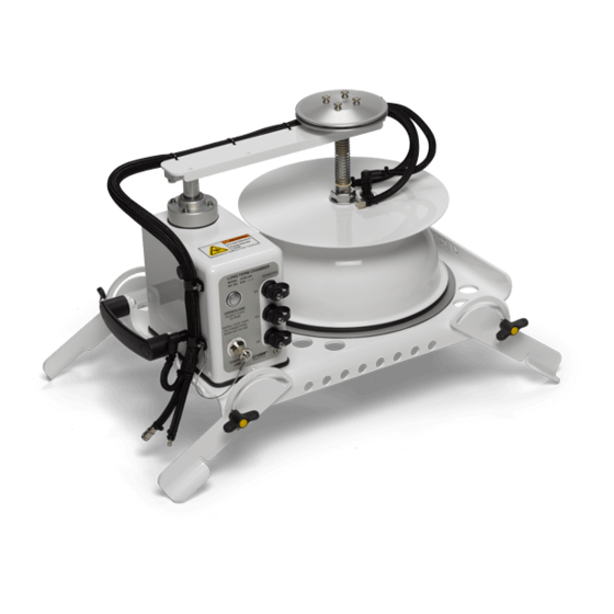
Multiplexer. If the 8100-104/C is used in single chamber mode with the LI-8100A, auxiliary sensors must be connected to the Auxiliary Sensor Interface, not the chamber itself. - Page 107 Using the Long-Term Chambers Swing Arm Pressure Vent Auxiliary Sensor Connections V2, V3, V4 Open/Close Button Control Line Chamber Connector Carrying Handle Chamber Gasket Adjustable Legs Figure 7-1. 8100-104 Long-Term Chamber. The 8100-104/C moves away from the soil collar when the measurement is complete.
-
Page 108: Changing The 8100-104/C Chamber Open Position
Using the Long-Term Chambers Changing the 8100-104/C Chamber Open Position The default open position is approximately 180° from the closed position, as shown in Figure 7-2. There are, however, five additional open positions (Fig. 7-3) that can be programmed using the Open/Close button on the chamber control panel. This can be useful for areas where the terrain, or obstructions, don’t permit the full 180°... -
Page 109: Using Auxiliary Sensors With The 8100-104/C
(p/n 8150-203) probes for use with the 8100-104/C are fitted with 8-pin connectors that mate with the connectors on the control panel of the chamber. If the 8100-104/C is to be used in single-chamber mode with the LI-8100A, any auxiliary sensors must be wired into the Auxiliary Sensor Interface, as described in Section 2, “Using the Auxiliary Sensor Interface”;... -
Page 110: Connecting The Long-Term Chambers To The Analyzer Control Unit Or Multiplexer
Using the Long-Term Chambers analyzer optical bench measures CO and H O concentrations simultaneously; these concentrations are then used to calculate flux rate. Analyzer Control Unit Diaphragm Pump 8100-104/C Chamber Analyzer Bench To Chamber From Chamber Filter Figure 7-5. The measurement flow path to the 8100-104/C Long-Term Chamber. Connecting the Long-Term Chambers to the Analyzer Control Unit or Multiplexer 8100-104/C Long-Term Chambers There are two short hoses connected to the 8100-104/C Long-Term Chambers;... -
Page 111: Making Measurements
Connect the LI-8100A and your computer using the appropriate serial cable, as described in Section 2, Initial Setup. Turn the LI-8100A on using the ON/OFF button on the inside panel of the Analyzer Control Unit. Wait for the IRGA Ready light to illuminate. Note that the chamber moves to its open position at system startup. - Page 112 Soil Area value and Total System Volume values are automatically displayed. The Temperature Source determines where the air temperature measurement used for the flux calculations is obtained. When using a LI-COR soil chamber, this field should always be set to ‘Chamber’, so that the temperature measurement is made using the thermistor located inside the chamber.
- Page 113 Chamber Volume to obtain the Total Volume. Measuring the Chamber Offset is described in Section 2, Using Soil Collars. Click on Apply to Port to send these values to the LI-8100A for implementation. Click on the Observation tab to open the Observation window.
- Page 114 Observation Length of 90 to 120 seconds is usually adequate. Note that the LI-8100A starts logging data when the chamber is actuated and starts to close. Raw, or Type 1 records are recorded throughout the entire observation period. The Elapsed Time (labeled Etime on the data output) does not increment, however, until the chamber is closed.
- Page 115 7-10 Using the Long-Term Chambers Post-purge The Post-purge is the amount of time during which air continues to flow through the chamber as it begins to open, after the measurement is complete. This is important in certain cases where environmental factors may influence the amount of CO or moisture that is present in the gas sampling lines.
- Page 116 7-11 Using the Long-Term Chambers Stop Observation if RH reaches… Enable the 'Stop Observation if RH reaches' check box and enter a relative humidity value (if humidity is a concern at the measurement site). The Observation will abort if the measured relative humidity in the chamber exceeds this value at any time during the Observation.
- Page 117 7-12 Using the Long-Term Chambers three 90-second observations on the chosen port. The maximum number of repeats is 12000 (Set To Max button). You can elect to turn off the flow pump between repeated measurements to conserve battery life and extend the life of the pump by enabling the check box.
-
Page 118: Software Setup Using The Li-8100A Apple Ios Software
Software Setup Using the LI-8100A Apple iOS Software The following discussion assumes that you have installed the LI-8100A application on your iPod Touch (or other iOS device), and have configured the LI-8100A and your iPod Touch to communicate via a wireless network, as described in Section 9, iOS Software Reference. - Page 119 7-14 Using the Long-Term Chambers Measurement Type The Measurement Type field allows you to toggle between Chamber measurements and Continuous measurements. Continuous measurements are used with the optional 8100-405 CO Mapping Kit to map CO concentrations across any transect of interest. In Continous mode, a single measurement of up to 24 hoours can be made.
- Page 120 7-15 Using the Long-Term Chambers Note that the LI-8100A starts logging data when the chamber is actuated and starts to close. Raw, or Type 1 records are recorded throughout the entire observation period. The Elapsed Time (labeled etime on the data output) does not increment, however, until the chamber is closed.
- Page 121 7-16 Using the Long-Term Chambers This is important in certain cases where environmental factors may influence the amount of CO or moisture that is present in the gas sampling lines. For example, in hot, moist conditions, you may want to increase the Post-purge to ensure that the gas sampling lines are purged of moisture that may condense in the lines, before the next measurement using that chamber is started.
- Page 122 Additional Log Fields Tap on Additional Log Fields to choose the values to be logged to memory. Data collected by the LI-8100A can be stored to the instrument's internal memory, or to an optional Compact Flash card. Data stored to the internal memory can be transferred to a Compact Flash card or to the PC at any time.
- Page 123 7-18 Using the Long-Term Chambers V2 Aux Input at voltage channel 2 (soil moisture). V3 Aux Input at voltage channel 3 (soil moisture). V4 Aux Input at voltage channel 4 (soil moisture). T1 Aux Input at thermocouple channel 1, in degrees C. T2 Aux Input at thermocouple channel 2, in degrees C.
- Page 124 The area of soil encompassed by the soil collar, in cm . Calculate the Soil Area from the inside diameter of the soil collar. The default values in the LI-8100A software are given for the 10 cm and 20 cm soil collars provided by LI-COR. Chamber Volume The Chamber Volume value includes the air inside the chamber, as well as from the tubing attached to the chamber.
- Page 125 Tap Don t to disable the selected data Transmit value. to enable all data Transmit All values, or to disable all Transmit None data values. to send the selected Send Update data fields to the LI-8100A for implementation.
- Page 126 Remove markup (see note below). CRC (Cyclic Redundancy Check) is an algorithm that is used to verify the integrity of the data. Before each data packet is sent by the LI-8100A, a CRC is calculated (pre-transmission) for that packet, and then appended to the packet.
- Page 127 A typical CRC will appear as <CRC>3067450353</CRC> Disable 'CRC' to remove CRC from the data. Note that the LI-8100A PDA applications do not use CRC checking. Note that when the LI-8100A outputs data, each field is "marked up" using eXtensible Markup Language (XML) to delimit that field.
- Page 128 Start button is pressed. Log To Data collected by the LI-8100A can be stored to the instrument's internal memory, or to an optional Compact Flash card; you can log to one or the other, but not both at the same time.
- Page 129 7-24 Using the Long-Term Chambers second Deadband, Obs. Delay of 2 minutes, and Obs. Count of 3. This protocol could then be repeated every hour for 240 hours (10 days). The resulting data set would include 240 measurements, with each measurement consisting of three 90-second observations.
-
Page 130: Section 8. Windows Software Reference (Single Chamber Mode)
Add/Remove button. Operation - Using the LI-8100A Software Data from the LI-8100A can be transferred to a computer for analysis, printing or storage using the RS-232 or Ethernet interfaces. The LI-8100A RS-232 port is configured as Data Terminal Equipment (DTE) with no hardware handshaking, and is bi-directional, meaning information can be transferred both into and out of the LI-8100A. -
Page 131: Connecting
File menu. You are asked to select the serial port to which the LI-8100A is connected or the IP address of the LI-8100A, if the LI-8100A is connected to a wired or wireless network (see Remote Networking below). -
Page 132: Using The Toolbar
LI-8100A parameters. You can change the variables that you want to monitor, displayed on the right side of the window, by clicking on the dots next to any variable and selecting a different one from the pop-up menu (above). -
Page 133: Communication Menu
Connect Opens the Connect dialog, where you can choose the serial (COM) port on the computer to which the LI-8100A is connected, or enter the IP address of the LI-8100A, if it is connected to a network. The Internet Protocol (IP) -
Page 134: Port Setup:chamber
Port Setup: Chamber The Chamber tab contains options for choosing the type of chamber that is connected to the LI-8100A, as well as entering any Volume Corrections, including chamber offset and soil area. Choose the type of chamber that is connected from the Chamber pull-down menu. - Page 135 Chambers sold by LI-COR provide an electronic signal when they are closed; this signal is used during various operations (e.g. during calibration) to indicate when the chamber is fully closed. Thus, when a LI-COR chamber is chosen from the menu, the ‘This chamber provides a “Closed” signal’ check box is automatically checked.
-
Page 136: Port Setup:observation
(discussed in Section 2, Initial Setup). The soil CO flux measurement requires an accurate estimate of the Total System Volume. The LI-8100A software uses the Chamber Offset and the Soil Area values to calculate the volume of air inside of the soil collar (Collar Volume). - Page 137 The Dead Band requirement changes depending upon the chamber geometry, system flow rate, and collar and site characteristics. Testing at LI-COR has indicated that a Dead Band between 10 and 60 seconds generally provides adequate mixing.
- Page 138 Windows Software Reference (Single Chamber Mode) until the Pre-purge has finished; again, in most cases this delay is unwanted, particularly when moving the chamber from collar to collar. For these reasons, you may want to use the Post-purge value instead of the Pre-purge; in other words, set the Pre-purge to zero, and set the Post-purge to 20-30 seconds, or more, depending on the conditions described above at “Pre- purge”.
-
Page 139: Port Setup:data Logging
8-10 Windows Software Reference (Single Chamber Mode) Port Setup: Data Logging The Data Logging page contains a number of Optional Data Fields that can be logged with each Observation. These fields are not used in any flux calculations. Choose Select All to enable all records, or Clear All to disable these records. If you want to perform flux calculations after each Measurement is completed, enable the ‘Perform Flux Computations’... -
Page 140: Port Setup:v1 (V2, V3, V4)
8-11 Windows Software Reference (Single Chamber Mode) Port Setup: V1 (V2, V3, V4) The V1, V2, V3, and V4 windows are the areas in which you can input the coefficients for linear external input devices connected to the Auxiliary Sensor Interface box. -
Page 141: Repeat
8-12 Windows Software Reference (Single Chamber Mode) The voltage ouput from the input devices connected to the Auxiliary Sensor Interface can be viewed in the Main Window. Repeat The Repeat Measurement page allows you to repeat the defined protocol at a regular clock interval. -
Page 142: Thermocouples
The Thermocouples window is the area in which you can input the coefficients for thermocouples attached to the Auxiliary Sensor Interface. There are 4 thermocouple channels (Type E, J, or T); choose the thermocouple type from the pull-down menu. Click Apply Changes to send the values to the LI-8100A. -
Page 143: Presets
Preset is saved, you can save it to the computer by clicking Transfer to PC, and choosing a destination for the file (by default, they are saved in a folder named Presets in the LI-8100A Program Files folder). Preset files are appended with a .81p file extension. -
Page 144: Continous Measurement
Application Note #135, entitled “Mapping CO Concentrations and Fluxes with the LI-8100A”, included with the 8100-405 kit, or in electronic format at www.licor.com/env/support. Data collected with the LI-8100A in continuous mode are formatted differently than those collected with a soil chamber. -
Page 145: Collecting Continuous Co2 Concentration Data
1. Connect the 8100-405 as shown in Figure 2 of the 8100-405 Instruction Manual. 2. Connect the intake tube to the Air In fitting on side panel of the LI-8100A Analyzer Control Unit. Bev-a-line tubing and fittings are included in the spare parts kit. -
Page 146: Adding Annotations
8-17 Windows Software Reference (Single Chamber Mode) 9. Stop the measurement manually at any time. Adding Annotations Annotations can be added at any time during a continuous measurement. These annotations will appear as a separate data column in the resulting .csv file. When converting the .csv file to .kml format using the included converter (described in the 8100-405 instruction manual), you will be prompted to process file annotations. -
Page 147: Start Measurement
8-18 Windows Software Reference (Single Chamber Mode) Start Measurement Measurement Configuration You can choose a defined set of measurement parameters from the Preset pull- down menu, or use the configuration as currently defined (see Measurement Configuration:Presets above). Measurement File Enter a File Name and optional Comments. The Comments appear only in the header information. -
Page 148: View Menu
Destination Data collected by the LI-8100A can be stored to the instrument's internal memory, or to an optional Compact Flash card; you can log to one or the other, but not both at the same time. -
Page 149: Error Log
8-20 Windows Software Reference (Single Chamber Mode) Error Log Opens a window that displays any logged errors that occurred during a measurement cycle. Click Clear Log to delete all messages, or Save Log to enter a filename and save the Error Log to a text file. Summary Records Opens a window that displays select records, including Status (linear or exponential flux calculation), Flux values and Flux CV for each observation. -
Page 150: Reports
8-21 Windows Software Reference (Single Chamber Mode) Reports Opens the Report window, which provides a variety of ways to view selected Observations. Choose Select Data File from the File menu, and choose the file whose Observations you want to view. The Observation tab displays the Observation’s data in tabular format. - Page 151 8-22 Windows Software Reference (Single Chamber Mode) The Flux Comparison tab allows you to plot flux values on a chart. Choose the number of flux data points to be plotted, and click Plot Fluxes. The Max Items denotes the number of points to plot. The data plotted on the graph are always the most recent in the file.
- Page 152 8-23 Windows Software Reference (Single Chamber Mode) Click on Values by Port to graph two specific data items for a given port. The points are data from the last (Max Items) observations. Select the variable to plot on each axis. Click Plot. To automatically scale the left and/or right axes, click on Chart Options.
- Page 153 8-24 Windows Software Reference (Single Chamber Mode) Click on Values by Observation to plot records by observation, on left and right axes, against elapsed time (ETime). Values by Observation displays all of the raw data values for a particular observation; this is used to view a single observation in detail.
- Page 154 8-25 Windows Software Reference (Single Chamber Mode) To automatically scale the left and/or right axes, click on Chart Options. Enable automatic scaling, and set the maximum and minimum values for the axes, if desired. To view the selected Observations in tabular format, click on View Table.
- Page 155 8-26 Windows Software Reference (Single Chamber Mode) Click Clear Chart to remove all data from the chart.
-
Page 156: Utilities Menu
Utilities Menu File Manager Opens the File Manager dialog, where you can move files from the LI-8100A to your computer or optional compact flash card. The Local PC window displays a directory tree of the files on your computer. The Internal Storage window displays the LI-8100A data files currently stored on the LI-8100A internal flash memory, and the amount of free memory available. -
Page 157: Manual Controls
8-28 Windows Software Reference (Single Chamber Mode) MB of free space are indicated, approximately 45 MB of LI-8100A data files may be stored. The file sizes listed in the directory list are actual size, however. If a compact flash card is present, the Compact Flash window also shows the amount of available memory on the card. - Page 158 8-29 Windows Software Reference (Single Chamber Mode) analyzer, as described in Section 5. In general, the Manual Controls are used for diagnostic purposes, and are not used when making typical measurements. Click the Close Chamber or Open Chamber button to manually close or open the attached soil chamber.
-
Page 159: Calibration
8-30 Windows Software Reference (Single Chamber Mode) The Flow tab contains controls for turning flow on or off to the LI-8100A. When a measurement is started, the LI-8100A flow rate is automatically set to the highest rate possible. Calibration Select Calibration to open the Calibration window. This is the area in which you set the zero and span of the infrared gas analyzer in LI-8100A Analyzer Control Unit. - Page 160 O correct for pressure fluctuations that may be present. To disable this correction, click on the Options tab and disable the ‘Enable Pressure Compensation’ check box. The LI-8100A uses a rectangular hyperbola for the CO calibration, and a third order polynomial for H O calibration.
-
Page 161: Charting
8-32 Windows Software Reference (Single Chamber Mode) to send the values to the LI-8100A for implementation; the constants are not automatically saved to the computer until you choose Save Constants. Charting Select Charting to open the Charting window (below). This is the window in which you can set up the parameters for plotting your real-time data. -
Page 162: Pc Data Logging
8-33 Windows Software Reference (Single Chamber Mode) X-Axis Max Sets the maximum value for the X axis (Time). The units for the X axis can be seconds or minutes. Press Start at any time to view the chart layout and begin displaying data. Note that you must press Stop to make changes to the chart parameters, and then press Start again to resume data display. - Page 163 8-34 Windows Software Reference (Single Chamber Mode) Choose the frequency at which to log data (seconds), and the delimiter for the data fields (tab or semicolon character). Use the Controls buttons to manually start or stop data logging, independent of any measurement protocol that is currently defined.
-
Page 164: Xml Monitor
XML Monitor The configuration grammar used to communicate with the LI-8100A is based upon a subset of XML (eXtensible Markup Language). XML relies on the use of tags to “Markup” or give structural rules to a set of data. The XML Monitor window is primarily a diagnostic tool that displays real-time XML communication;... -
Page 165: 8100 Menu
The Volume is used as default value for the IRGA in the LI-8100A. In most cases this value should not be changed. The default value is 19 cm for the IRGA volume. -
Page 166: Networking
Click on Apply to send these values to the LI-8100A for implementation. Networking The LI-8100A can be connected to a PC or PDA via a wireless or wired network if desired. The Remote Network Setup window allows you to configure networking options for the LI-8100A. - Page 167 Figure 8-1. On an Ad-hoc network, each device can communicate with other wireless enabled devices. The LI-8100A can also be connected to a specific hardware access point (below). For example, this could be a wireless router/switch, or it can be a Software Access Point that runs on a computer equipped with a wireless network interface card.
- Page 168 Network Setup In order to communicate with other devices on any type of network, the LI-8100A must be given a unique IP address, netmask, and gateway. Additionally, if communicating on a wireless network, the connection type, network name, channel and data encryption options can be set.
- Page 169 The network name, or SSID (Service Set Identifier), is a name given to a wireless local-area network (WLAN). Each device that needs to communicate must have the same SSID. The LI-8100A supports a network name of up to 30 characters.
-
Page 170: Date And Time
WEP (Wired Equivalent Policy) is an encryption standard built into 802.11b, and is supported by the LI-8100A. If data encryption is enabled, the same 40-bit (5 character) key must be entered on all devices of the WLAN. The key is used for data encryption and decryption. -
Page 171: Outputs
Choose the raw data values to be sent to the RS-232 port and output frequency (seconds). Note that when the LI-8100A outputs data, each field is "marked up" using eXtensible Markup Language (XML) to delimit that field. For example, when a CO value is output, the data value is placed between two "tags"... -
Page 172: Help Menu
CRC (Cyclic Redundancy Check) is an algorithm that is used to verify the integrity of the data. Before each data packet is sent by the LI-8100A, a CRC is calculated (pre-transmission) for that packet, and then appended to the packet. When the client (e.g. - Page 173 8-44 Windows Software Reference (Single Chamber Mode)
-
Page 174: Section 9. Apple Ios Software Reference (Single-Chamber Mode)
(802.11b) that features an extended form factor, low power consumption, and built-in antenna. The wireless PC card fits into either of the two PC card slots in the LI-8100A Analyzer Pack (see Section 2, Initial Setup). Handheld Requirements for Wireless Communication At the time of this printing, LI-COR is offering the Apple iPod Touch as part of a wireless package for use with the LI-8100A. -
Page 175: Handheld Software Requirements
Apple iOS Software Reference (Single Chamber Mode) go to LI-COR's LI-8100A support page on the web at www.licor.com to see the most current handheld recommendations. For the purposes of this manual, descriptions and discussion for using the LI-8100A with a handheld device will reference the Apple iOS software. -
Page 176: The Setup Menu
Apple iOS Software Reference (Single Chamber Mode) Descriptions of most terms used in the LI-8100APP can be viewed by tapping on the text of the term for which you want to view help. The Setup Menu Measurement Presets Opens the Measurement Presets page, where you can define up to 19 different configurations containing measurement setup parameters. -
Page 177: Measurement Protocol
Apple iOS Software Reference (Single Chamber Mode) By default, the presets are unnamed until they are saved with a new name. When the experimental parameters have been defined, tap Save Current to name the preset. Select a different preset by scrolling to the desired preset name, and tap Load to activate that preset’s predefined parameters. - Page 178 Apple iOS Software Reference (Single Chamber Mode) Measurement Type The Measurement Type allows you to choose between standard Chamber measurements, or Continuous measurements when used with the optional 8100- 405 CO Mapping Kit. In Continuous mode, a single measurement of up to 24 hours can be made.
- Page 179 Apple iOS Software Reference (Single Chamber Mode) Note that the LI-8100A starts logging data when the chamber is actuated and starts to close. Raw, or Type 1 records are recorded throughout the entire observation period. The Elapsed Time (labeled etime on the data output) does not increment, however, until the chamber is closed.
- Page 180 Apple iOS Software Reference (Single Chamber Mode) Tap Maximum Time to set the Dead Band to the maximum time of 999 seconds, or Minimum Time to set the Dead Band to the minimum time of 0 seconds. Observation Count You can make repeated observations under the same set of parameters by setting the Observation Count to reflect the number of times to repeat the observation.
- Page 181 Apple iOS Software Reference (Single Chamber Mode) Tap Max Count to set the number of Observations to the maximum of 32767 observations, or Min Count to set the number of Observations to the minimum of 1 observation. Note that in most cases, it may be more desirable from a scientific and/or statistical standpoint to replicate measurements on multiple soil collars rather than repeating them on the same collar.
- Page 182 Apple iOS Software Reference (Single Chamber Mode) Select the hours, minutes, and seconds for Pre-Purge Time (30 seconds in the example at left) and tap Send Update. When an observation is complete, the chamber will automatically rise up off of the soil collar.
- Page 183 Additional Log Fields Tap on Additional Log Fields to choose the values to be logged to memory. Data collected by the LI-8100A can be stored to the instrument's internal memory, or to an optional Compact Flash card. Data stored to the internal memory can be transferred to a Compact Flash card or to the PC at any time.
- Page 184 Log All to disable all data values. Log None to send the selected Send Update data fields to the LI-8100A for implementation. The additional data values that can be logged are as follows: Label Description Case Temperature (°C) Air temperature inside the Analyzer Control Unit case.
-
Page 185: Area And Volumes
(discussed in Section 2, Initial Setup). The soil CO flux measurement requires an accurate estimate of the Total System Volume. The LI-8100A software uses the Chamber Offset and the Soil Area values to calculate the volume of air inside of the soil collar. This value is, in turn, added to the Chamber Volume to obtain the Total Volume. - Page 186 The Soil Area is the surface area of soil encompassed by the soil collar. Select 10 cm if you are using the Survey Chamber with a 10 cm soil collar from LI-COR, or 20 cm if you are using the 20 cm Survey Chamber or Long-Term Chamber with a 20 cm soil collar from LI-COR;...
- Page 187 In this case, the thermistor would be connected to the Auxiliary Sensor Interface, and measured on one of Auxiliary (Voltage) channels 1-4. Under ‘Chamber Temperature Mapped to:’ choose Chamber during normal operation with LI-COR soil chambers, or choose the Auxiliary channel to which an external thermistor is connected.
-
Page 188: Start Measurement
Note that all LI-COR soil chambers provide an electronic signal when the chamber is closed; if you have constructed a custom chamber for use with the LI-8100A that does not provide an electronic “closed” signal, make sure that ‘Chamber signals “Closed”... - Page 189 9-16 Apple iOS Software Reference (Single Chamber Mode) The File Name and Treatment Labels can be up to 30 characters in length. The Comments can be up to 100 characters in length. In the File Name page, enable the 'Append Data To File' check box to add new data at the end of an existing file.
- Page 190 9-17 Apple iOS Software Reference (Single Chamber Mode) Tap Standard to log data to a single file that is not split and/or appended. Tap Split to create a new file every Day or Week; note that you must first enable the Repeat Measurement field (below) to use this function.
- Page 191 9-18 Apple iOS Software Reference (Single Chamber Mode) For example, you could specify a 90 second Obs. Length, 45 second Deadband, Obs. Delay of 2 minutes, and Obs. Count of 3. This protocol could then be repeated every hour for 240 hours (10 days). The resulting data set would include 240 measurements, with each measurement consisting of three 90-second observations on the chosen port.
-
Page 192: The View Menu
Apple iOS Software Reference (Single Chamber Mode) The View Menu Instrument Status Opens the Instrument Status page, where you can view the current operating state of the LI-8100A. The Instrument Status page displays the user- entered instrument name and serial number, the instrument software version, input... -
Page 193: Summary Page
9-20 Apple iOS Software Reference (Single Chamber Mode) Summary Page Opens a page where you can view the summary records for the most recent measurement. Note that during normal operation the Summary Page will switch to the Monitor page when a new measurement is started; turn on ‘Hold on This Page’ to retain the Summary Page on the display when a new measurement starts. -
Page 194: The Utilities Menu
LI-8100A internal memory. Tap File Remove/Format (CF) to format or delete selected files from the compact flash card. Tap File Digest View (Internal) to display a list of files on the LI-8100A internal memory, or File Digest View (CF) to display a list of the files on the Compact Flash card. - Page 195 9-22 Apple iOS Software Reference (Single Chamber Mode) Tap Select File To View Content Digest to open the selected file. The Observation Digest Viewer appears.
- Page 196 Retrieve Observation Content to view the contents of the selected Observation. Tap Storage Operations to delete all files from the LI-8100A internal memory or compact flash card, or to move all files to the compact flash card.
-
Page 197: Manual Controls
9-24 Apple iOS Software Reference (Single Chamber Mode) Copy All Files to CF Card: Copies all files from the LI-8100A internal memory to the optional compact flash card. Delete All Files From Internal Flash: Removes all files from the LI-8100A internal memory. -
Page 198: Calibration
Calibration Opens the Calibration page, where you set the zero and span of the infrared gas analyzer in the LI-8100A Analyzer Control Unit. Step-by-step instructions for performing user calibrations are given in Section 5. - Page 199 O zero and span calibrations are found on the Calibration page. If new constants are entered in this page, tap Send Update to send the values to the LI-8100A for implementation (note that the dates will not change). The calibration functions for both CO...
-
Page 200: The 8100 Menu
9-27 Apple iOS Software Reference (Single Chamber Mode) The 8100 Menu Instrument Settings Opens the Instrument Settings page, where you can view and/or edit the current operating state of the LI-8100A. - Page 201 IRGA Averaging: The amount of averaging of the CO and H O signals from the IRGA. The IRGA in the LI-8100A is sampled at 2 Hz. With 4 second signal averaging (the default), 8 data points are averaged for each CO or H O value.
-
Page 202: Auxiliary Inputs
9-29 Apple iOS Software Reference (Single Chamber Mode) IRGA Volume: Volume of air (cm ) in the optical bench and associated tubing inside the Analyzer Control Unit case. In most cases this number should not be changed. Auxiliary Inputs The Auxiliary Inputs page is the area in which you can input the coefficients for linear external devices connected to the Auxiliary Sensor Interface. -
Page 203: Outputs
RS-232 port, or via the wireless card or Ethernet port, if you are using the LI-8100A in a wireless or wired Ethernet network. This is primarily used when capturing raw data values with an external data logging device. - Page 204 9-31 Apple iOS Software Reference (Single Chamber Mode) Data can be output via RS-232 or TCP/IP at intervals between 1 and 20 seconds. RS-232 Output Fields Choose the data values to be sent to the RS-232 port.
- Page 205 Transmit All values, or to disable all Transmit None data values. to send the selected Send Update data fields to the LI-8100A for implementation. The data values that can be output are as follows: Label Description Time Instrument time. 10s Flux Ten second running estimate of soil CO flux rate.
- Page 206 Remove markup (see note below). CRC (Cyclic Redundancy Check) is an algorithm that is used to verify the integrity of the data. Before each data packet is sent by the LI-8100A, a CRC is calculated (pre-transmission) for that packet, and then appended to the packet.
-
Page 207: The Help Menu
9-34 Apple iOS Software Reference (Single Chamber Mode) Send RS-232 Data Every Sets the frequency at which to log data (seconds). TCP/IP Output Fields Tap on the TCP/IP field to configure the data values to be sent via the wireless card or Ethernet port, if desired. -
Page 208: About Li-8100A
9-35 Apple iOS Software Reference (Single Chamber Mode) About LI-8100A Displays a screen that shows the LI-8100APP version number and contact information for LI-COR. -
Page 209: Section 10. Using The Li-8150 Multiplexer
Using the LI-8150 Multiplexer About the LI-8150 The LI-8150 Multiplexer is an accessory for the LI-8100A that makes it possible to connect as many as 16 individual chambers at one time, which are sampled and controlled by the LI-8100A Analyzer Control Unit. -
Page 210: What's What
If you have just taken delivery of your LI-8150 check the packing list to verify that you received everything ordered, including the following items: Cable/Hose Assembly Contains all cables and hoses for connection to the LI-8100A Analyzer Control Unit. Setup instructions are given later in this section. Spare Parts Kit This box contains replacement parts for your LI-8150. - Page 211 10-3 Using the LI-8150 Multiplexer Figure 10-2. 8150-770 AC Power Supply. The 8150-770 has an input voltage range of 115-120 or 230-240VAC; the range is switch-selectable, and must be configured before applying power. Loosen the 4 screws in each corner on the top panel of the power supply. Slide the top cover away from the supply;...
- Page 212 Power Supply, make sure that it is rated for outdoor use. Connect the power cord between the Power Supply and Multiplexer; plug the AC cord into mains power, and then power the LI-8150 and LI-8100A on. The 8150-770 AC Power Supply can rest on the ground, or be mounted off of the ground using holes in the 8150-770 box.
-
Page 213: Cable/Hose Extension Assembly
The AC Power Supply can be used in combination with the batteries located inside the LI-8100A Analyzer Control Unit; if AC power is interrupted, the batteries will continue to power the LI-8100A. When AC power is restored, the measurement will continue at the point in which it was interrupted. -
Page 214: Eight To Sixteen Port Upgrade Field Installation (8150-916-1)
8 (or 16) chambers (or gas lines) at a time to the IRGA in the LI-8100A. This circuit provides air flow to and from the chamber while maintaining the pressure in the IRGA at the ambient level. This pneumatic circuit also monitors the approximate flow rate to and from the chamber(s), and provides a method to test for leaks throughout the system. - Page 215 Sample gas from the chamber is filtered as it enters the pneumatic circuit; it is filtered again in the LI-8100A before it is measured by the IRGA. A diaphragm pump is used to circulate the sample gas to and from the multiplexer and the selected chamber.
- Page 216 On either side of the LI-8150 case are connections for up to 8 chambers. The left side shown above (optional) has only chamber connections; the right side (not pictured) also has power and LI-8100A connections. The raised platform in the case contains the On/Off switch and central Control Panel (below), which provides a display of the active chamber and valve.
- Page 217 10-9 Using the LI-8150 Multiplexer Power – Illuminates when power is applied to the instrument, and the power switch is turned On. Check Error Log – illuminates when an error condition is detected (e.g. a chamber failed to close, flow rate is too low, etc.). Power The Error Log can be viewed in the Windows application software, under the...
-
Page 218: Cable Connections
Aux. Sensor Interface on the LI-8100A, and to the port labeled LI-8100A on the LI-8150. The second hose bundle has three air hoses and an electronic cable. These hoses are connected to the side panel of the Analyzer Control Unit, as shown below. -
Page 219: Li-8150
LI-8150 Attach the large bulkhead connector to the port labeled LI-8100A. Attach one end of the power cable to the connector labeled PWR (Figure 10-6). Attach the round control cable to the connector labeled CTRL. -
Page 220: Chambers
10-12 Using the LI-8150 Multiplexer The hose for the pump (labeled P) has a male fitting. The hose for Air Out (labeled O) also has a female fitting; this hose has a piece of black shrink wrap. The Air In hose has a female fitting, and attaches to the port marked I. -
Page 221: Connecting Auxiliary Sensors
104/C Long-Term Chambers are pre-wired with plugs on the exterior of the chamber; when soil temperature or soil moisture probes are purchased from LI-COR for use with the Multiplexer, they are fitted with plugs as well, which snap onto the mated connectors on the chamber. For sensors from other manufacturers, a plug with bare wire leads (p/n 392-08577) is provided that can be attached to the sensor’s wire leads;... - Page 222 Figure 10-9. A plug with bare wire leads (p/n 392-08577) can be used to attach sensors from other manufacturers to the 8100-104/C Long-Term Chambers. Note that when the Multiplexer is attached to the LI-8100A, the Auxiliary Sensor Interface cannot be attached to the LI-8100A; thus, thermocouples cannot be...
-
Page 223: Measurement Quick Start
Turn the Multiplexer on first using the power switch on the inside panel, and then turn the LI-8100A on using the ON/OFF button on the keypad on the inside panel of the Analyzer Control Unit. If everything is connected properly, all chambers connected will automatically open in series (4 at a time). - Page 224 10-16 Using the LI-8150 Multiplexer leak test. See Performing a Leak Test below if you want to perform a leak test, or want more information. Choose Measurement Configuration from the Setup menu. The Multiplex Configuration dialog appears. Click a category here...
- Page 225 Using the LI-8150 Multiplexer Chamber Offset), and Extension Tube Volume values (237 cm for 15 m Extension Tube from LI-COR). If you are not using an extension tube, enter ‘0’ for the Extension Tube Volume. The Temperature Source determines where the air temperature measurement used for the flux calculations is obtained.
- Page 226 10-18 Using the LI-8150 Multiplexer 8d) Click on the Data Logging tab. Click on the Select All button, if the Optional Data Fields are not all selected. 8e) Optionally, you can click on the V2, V3, or V4 tabs to choose the type of probe (or thermistor) for each input on the 8100-104/C chamber.
- Page 227 10-19 Using the LI-8150 Multiplexer When the chambers are connected properly, they will be detected in software, and shown here. In the example above, a single chamber was detected on port 1. Chambers can be measured in any desired sequence, using the Port Sequence entry field. For example, if we wanted to measure the chambers in the order in which they were detected, we can simply click the ‘Use as Sequence’...
- Page 228 10-20 Using the LI-8150 Multiplexer Offsets and/or Treatment Labels vary between soil collars, you will need to enter them individually; this can be done in the Quick Settings part of this dialog. Simply choose the port, and then enter Treatment Label and Chamber Offset for each port.
- Page 229 10-21 Using the LI-8150 Multiplexer 10. Choose Summary Records from the View menu. You can view a brief summary of each observation, in series, including flux values, by clicking Previous or Next. Click Close when finished reviewing the records.
- Page 230 We’ll move the file just created to the computer, where we can open it in the LI-8100A File Viewer program for further analysis. Locate the newly created file in the Internal Storage list box (Test2.81x in the example above). Click and drag the file icon into the Local PC list box, to the desired location (i.e.,...
- Page 231 12. Locate the file transferred above and double-click on the file icon; LI-8100A data files are associated, and automatically open with, the LI-8100A File Viewer program (they have a .81x file extension). The File Viewer program will open, and will display a summary view of all...
- Page 232 10-24 Using the LI-8150 Multiplexer Select an observation by double-clicking on it (Obs. 31 in the example above). An Observation View appears, where you can view all final variables collected, as well as view and/or perform additional regression analyses, if desired.
- Page 233 10-25 Using the LI-8150 Multiplexer Click on the Regression Analysis tab to view a regression plot of the chosen observation.
-
Page 234: Performing A Leak Test
To perform the leak test, the bellows circuit in the LI-8100A (not used during normal operation for the Long-Term chambers) is used to evacuate the system. The... - Page 235 LI-8100A and the Multiplexer. A small fixture (p/n 9981-142) consisting of a short piece of tubing, and a male and female connector, is included in the spares kit, which forms a closed loop between the air input and output ports (Figure 10-15 below).
- Page 236 10-28 Using the LI-8150 Multiplexer Mate the male and female connectors at the chamber end of the extension tubing. 2. Make sure that at least one port is left open; you can disconnect the tubing at the chamber end, without mating the connectors, or simply disconnect at the Multiplexer side panel.
- Page 237 Enable the check boxes next to the ports to be tested. Choose a purge port to be left open. Enable the ‘8100 to Mux’ check box to test the air lines between the LI-8100A and the Multiplexer (Port 0). c. Click on the Run Test button. Each selected port will be tested in sequence.
- Page 238 10-30 Using the LI-8150 Multiplexer b. Enable the ‘Include LI-8100 to Multiplex lines’ box to test the air lines between the LI-8100A and the Multiplexer. Tap on the Port Sequence field.
- Page 239 10-31 Using the LI-8150 Multiplexer The Leak Test page will display the results of the test, using the following symbols: p = pass f = fail x = cancelled o = in queue - = not tested c. Tap to enable the ports to be tested. Choose a purge port to be left Test open (#16 in the example below).
-
Page 240: Using The Windows Interface Software With The Multiplexer
Using the LI-8150 Multiplexer Using the Windows Interface Software with the Multiplexer Data from the LI-8100A can be transferred to a computer for analysis, printing or storage using the RS-232 interface. Section 8 contains instructions for using the Windows software with the LI-8100A and a single soil chamber; this section details how to use the Windows software when the Multiplexer is connected to the LI-8100A. -
Page 241: Using The Toolbar
The Main window displays selected data variables on the right side of the window, as well as the progress of the current measurement and the status of various LI-8100A and LI-8150 parameters. If the Multiplexer is detected, the status window will display ATTACHED; detected chambers will also be displayed on their corresponding ports. -
Page 242: Communication Menu
Connect Opens the Connect dialog, where you can choose the serial (COM) port on the computer to which the LI-8100A is connected, or enter the IP address of the LI-8100A, if the instrument is connected to a wireless network. The Internet Protocol (IP) -
Page 243: Disconnect
10-35 Using the LI-8150 Multiplexer Disconnect Terminates communication between the Windows application software and the LI-8100A. Setup Menu Measurement Configuration Opens the Multiplex Configuration window, where you can define the measurement protocol, data logging options, flow rate, voltage inputs, and chamber offset values. - Page 244 Choose the type of chamber that is connected to the active port from the Chamber pull-down menu. The choices are: Custom – a user-built chamber, or tubing used for profiling studies. Long Term – LI-COR p/n 8100-101 Long Term – LI-COR p/n 8100-104 Long Term Clear – LI-COR p/n 8100-104C...
- Page 245 Chambers sold by LI-COR provide an electronic signal when they are closed; this signal is used during various operations (e.g. during calibration) to indicate when the chamber is fully closed. Thus, when a LI-COR chamber is chosen from the menu, the “This chamber provides a “Closed” signal” check box is automatically checked.
-
Page 246: Port Setup:observation
Chamber pull-down menu. Enter the Soil Area value (317.8 cm for the 8100-101 or 8100-104), Chamber Offset, and Extension Tube Volume (237 for 15 m Extension Tube from LI-COR). If you are not using a chamber extension tube, enter zero for the Extension Tube Volume value. - Page 247 The Dead Band requirement changes depending upon the chamber geometry, system flow rate, and collar and site characteristics. Testing at LI-COR has indicated that a Dead Band between 10 and 60 seconds generally provides adequate mixing (30 seconds is a good starting point if you are new to the system).
- Page 248 10-40 Using the LI-8150 Multiplexer Chamber Chamber Chamber Chamber Is Open Closes Opens Closes Observation Length Summary Records Logged Post- Dead Data Dead Data purge Band Logged Band Logged Pre-purge Pre-purge (optional) (optional) Range for Summary Records Observation #1 Observation #2 Measurement (includes n observations) Enable the 'Stop observation if RH reaches' check box and enter a relative humidity...
-
Page 249: Port Setup:data Logging
10-41 Using the LI-8150 Multiplexer Port Setup: Data Logging The Data Logging page contains a number of Optional Data Fields that can be logged with each Observation. These fields are normally not used in any calculations; if the Temperature Source, however, is mapped to V2, V3, or V4 (see Chamber tab earlier in this section), that temperature may be used in calculations. -
Page 250: Port Setup:v2 (V3, V4)
10-42 Using the LI-8150 Multiplexer Port Setup: V2 (V3, V4) The V2, V3, and V4 windows are the areas in which you can input the coefficients for linear external input devices connected to the 8100-104/C chamber (V1 is dedicated for measuring Multiplexer flow rate). There is a General Purpose Input, a dedicated input for the Decagon EcH O or Delta-T Theta soil moisture probes, and a Thermistor input that can be monitored on any of V2, V3, or V4 voltage... - Page 251 When using the 8100-104 or -104C chambers, the sonic anemometer is connected directly to the chamber, as shown in Figure 10-16. Sonic Anemometer on V2 8100-104 on Port #7 LI-8150 LI-8100A Figure 10-16. Sensor output can be fixed to a specific port for constant monitoring (8100- 104 shown).
-
Page 252: Port Sequence
They can, however, be measured in any desired sequence by entering the order at Port Sequence. Enter the port sequence, separated by commas (e.g. 1,8,8,13,1,9). When LI-COR chambers are attached to the Multiplexer, they are automatically detected, and displayed at Detected Chambers. If you want to measure the chambers in the order they were detected, click on Use as Sequence. -
Page 253: Repeat
10-45 Using the LI-8150 Multiplexer to query the system again; this is useful if a chamber was added, and you want to system to ‘find’ the added chamber. You can also sample ports where there are no chambers (or custom chambers) attached;... -
Page 254: Port Tools
10-46 Using the LI-8150 Multiplexer For example, you could specify a 90 second Obs. Length, 45 second Deadband, Pre-purge time of 2 minutes, and Obs. Count of 3. This protocol could then be repeated every hour for 240 times (10 days). The resulting data set would include 240 measurements, with each measurement consisting of three 90-second observations on the chosen port. - Page 255 10-47 Using the LI-8150 Multiplexer Choose the port whose and choose as many ports as configuration you want desired here to copy to to copy here… If Treatment Labels and/or Chamber Offsets vary between ports, choose the port here, enter Treatment Label and Chamber Offset, and click Apply Choose the port whose protocol has been previously defined (#1 in the example above), and then choose the ports to which you want to copy this protocol.
-
Page 256: Presets
Preset is saved, you can save it to the computer by clicking Transfer to PC, and choosing a destination for the file (by default, they are saved in a folder named Presets in the LI-8100A Program Files folder). Preset files are appended with a .81p file extension. -
Page 257: Start Measurement
10-49 Using the LI-8150 Multiplexer Start Measurement Measurement Configuration You can choose a defined set of measurement parameters from the Preset pull- down menu, or use the configuration as currently defined (see Measurement Configuration:Presets above). Measurement File Enter a File Name and optional Comments. The Comments appear only in the header information. -
Page 258: View Menu
Destination Data collected by the LI-8100A can be stored to the instrument's internal memory, or to an optional Compact Flash card; you can log to one or the other, but not both at the same time. -
Page 259: Error Log
10-51 Using the LI-8150 Multiplexer Click Close to close the window. Error Log Opens a window that displays any logged errors that occurred during a measurement cycle. Click Clear Log to delete all messages, or Save Log to enter a filename and save the Error Log to a text file. -
Page 260: Reports
10-52 Using the LI-8150 Multiplexer Reports Opens the Report window, which provides a variety of ways to view selected Observations. Choose Select Data File from the File menu, and choose the file whose Observations you want to view. The Observation tab displays the Observation’s data in tabular format. Choose the Observation number using the scroll arrows (or just type it), and click View Observation. - Page 261 10-53 Using the LI-8150 Multiplexer The Flux Comparison tab allows you to plot flux values on a chart. The flux values can be plotted for each port; e.g. you can plot fluxes of all ports concurrently. Choose the number of flux data points to be plotted, and click Plot Fluxes.
- Page 262 10-54 Using the LI-8150 Multiplexer Click on Values by Port to plot records by port, on left, right, and X axes. Choose the Port (Chamber) whose records you want to plot, and then select the variable to plot on each axis. Click Plot. To automatically scale the left and/or right axes, click on Chart Options.
- Page 263 10-55 Using the LI-8150 Multiplexer Click on Values by Observation to plot records by observation, on left and right axes, against elapsed time (ETime). Choose the Observation whose records you want to plot, and then select the variable to plot on each axis. Click Plot. To automatically scale the left and/or right axes, click on Chart Options.
- Page 264 10-56 Using the LI-8150 Multiplexer...
-
Page 265: Utilities Menu
LI-8100A are compressed. Therefore, the free memory available on the LI-8100A may not be indicative of how many files can be stored there. Files are compressed at a ratio of roughly 3:1, meaning if 15 MB of free... -
Page 266: Manual Controls
Opens the Manual Controls dialog, where you can use manual chamber controls to open or close the chambers, turn the LI-8100A or Multiplexer flow on or off, turn the bellows pump off, set voltage inputs to specified ports, and perform a leak test on the Multiplexer. - Page 267 10-59 Using the LI-8150 Multiplexer In general, the Manual Controls are used for diagnostic purposes, and are not used when making typical measurements. Choose the chamber number that you want to manually open or close, and click the Close Chamber or Open Chamber button. Click Scan Ports to force the system to detect chambers connected to the system.
- Page 268 The Flow tab contains controls for turning the flow rate on or off for both the LI-8100A and LI-8150. Flow to the individual ports can be turned on or off by choosing the Gas Port whose flow you want to turn on or off, and clicking Set.
- Page 269 10-61 Using the LI-8150 Multiplexer The Inputs tab allows you to manually set the voltage input that is displayed on the Main page, and on the LI-8150 control panel. Choose the voltage input (V2, V3, or V4) and the gas port containing the sensor whose voltage output you want to monitor, and click Set.
-
Page 270: Calibration
Calibration Select Calibration to open the Calibration window. This is the area in which you set the zero and span of the infrared gas analyzer in LI-8100A Analyzer Control Unit. Step-by-step instructions for performing user calibrations are given in Section... - Page 271 Save Values. Click Load Values to restore the values in this window using the file on the PC. If new constants are entered in this window, click Apply to send the values to the LI-8100A for implementation; the constants are not automatically saved to the computer until you choose Save Constants.
-
Page 272: Charting
10-64 Using the LI-8150 Multiplexer Charting Select Charting to open the Charting window (below). This is the window in which you can set up the parameters for plotting your real-time data. Two charts can be plotted simultaneously, using Y axes on either side of the chart. Series 1 The Series 1 options are used to plot a chart with the Y axis on the left side of the chart. -
Page 273: Pc Data Logging
10-65 Using the LI-8150 Multiplexer Press Start at any time to view the chart layout and begin displaying data. Note that you must press Stop to make changes to the chart parameters, and then press Start again to resume data display. Click on Save Chart to save the plot as currently displayed in the window to a .bmp file. - Page 274 RH (%) Relative humidity inside the soil chamber. V1/Mux Flow Output at voltage channel 1 (multiplexer flow to LI-8100A when attached). Output at voltage channel 2. Output at voltage channel 3. Output at voltage channel 4. Vin (volts) Input (battery) voltage.
-
Page 275: Xml Monitor
Using the LI-8150 Multiplexer XML Monitor The configuration grammar used to communicate with the LI-8100A is based upon a subset of XML (eXtensible Markup Language). XML relies on the use of tags to “Markup” or give structural rules to a set of data. The XML Monitor window is primarily a diagnostic tool that displays real-time XML communication;... -
Page 276: 8100 Menu
The Volumes are used as default values for the IRGA in the LI-8100A, and the tubing in the LI-8150 Multiplexer. In most cases these values should not be changed. -
Page 277: Networking
Click on Apply to send these values to the LI-8100A for implementation. Networking The LI-8100A can be connected to a PC or PDA via a wireless or wired network if desired. The Remote Network Setup window allows you to configure networking options for the LI-8100A. - Page 278 Figure 10-17. On an Ad-hoc network, each device can communicate with other wireless enabled devices. The LI-8100A can also be connected to a specific hardware access point. For example, this can be a wireless router/switch, or it can be a Software Access Point that runs on a computer equipped with a wireless network interface card.
- Page 279 Figure 10-18. A hardware access point can be used to bridge wireless and wired network devices. Network Setup In order to communicate with other devices on any type of network, the LI-8100A must be given a unique IP address, netmask, and gateway. Additionally, if...
- Page 280 The netmask is a set of 4 octets used to separate an IP address into two parts; the network address and the host address. If you are using LI-COR's recommended IP address range, the netmask should be set to 255.255.255.0.
-
Page 281: Date And Time
The network name, or SSID (Service Set Identifier), is a name given to a wireless local-area network (WLAN). Each device that needs to communicate must have the same SSID. The LI-8100A supports a network name of up to 30 characters. A range of radio frequencies between 2.4 and 2.5 GHz have been designated for public use in most countries. -
Page 282: Outputs
10-74 Using the LI-8150 Multiplexer Click OK to dismiss the dialog and accept the change(s). Outputs Opens the Outputs dialog, where you can configure the raw data values that are sent by the instrument via the RS-232 port, or via the Ethernet card. This is primarily used when capturing raw data values with an external data logging device. -
Page 283: Help Menu
CRC (Cyclic Redundancy Check) is an algorithm that is used to verify the integrity of the data. Before each data packet is sent by the LI-8100A, a CRC is calculated (pre-transmission) for that packet, and then appended to the packet. When the client (e.g. - Page 284 10-76 Using the LI-8150 Multiplexer...
-
Page 285: Using The Li-8100App For Apple Ios
Using the LI-8150 Multiplexer Using the LI-8100APP for Apple iOS Locate the LI-8100A program icon and tap the icon to start the program. There are six menus on the LI-8100APP main page; Connect, Setup, View, Utilities, 8100, and Help. Tap Connect to view a list of instruments to which you can connect. -
Page 286: The Setup Menu
10-78 Using the LI-8150 Multiplexer The Setup Menu Measurement Preset Opens the Measurement Preset page, where you can define up to 19 different configurations containing measurement setup parameters. These parameters can be saved and recalled for later use, without the need to redefine experimental parameters before each experiment. -
Page 287: Measurement Protocol
10-79 Using the LI-8150 Multiplexer By default, the presets are unnamed until they are saved with a new name. When the experimental parameters have been defined, tap Save Current to name the preset. Select a different preset by scrolling to the desired preset name, and tap Load to activate that preset’s predefined parameters. - Page 288 (discussed in Section 2, Initial Setup). The soil CO flux measurement requires an accurate estimate of the Total System Volume. The LI-8100A software uses the Chamber Offset and the Soil Area values to calculate the volume of air inside of the soil collar. This value is, in turn, added to the Chamber Volume, Multiplex Volume and Extension Tube Volume (if present) to obtain the Total Volume.
- Page 289 Observation Length of 90 to 120 seconds is usually adequate. Note that the LI-8100A starts logging data when the chamber is actuated and starts to close. Raw, or Type 1 records are recorded throughout the entire observation period. The Elapsed Time (labeled etime on the data output) does not increment, however, until the chamber is closed.
- Page 290 Using the LI-8150 Multiplexer Dead Band requirement changes depending upon the chamber geometry, system flow rate, and collar and site characteristics. Testing at LI-COR has indicated that a Dead Band between 10 and 60 seconds generally provides for adequate mixing (30 seconds is a good starting point if you are new to the system).
- Page 291 10-83 Using the LI-8150 Multiplexer Post-purge The Post-purge is the amount of time during which air continues to flow through the chamber as it begins to open, after the Observation is complete. This is important in certain cases where environmental factors may influence the amount of CO or moisture that is present in the gas sampling lines.
- Page 292 Additional Log Fields Tap on Additional Log Fields to choose the values to be logged to memory. Data collected by the LI-8100A can be stored to the instrument's internal memory, or to an optional Compact Flash card. Data stored to the internal memory can be transferred to a Compact Flash card or to the PC at any time.
- Page 293 Log All to disable all data values. Log None to send the selected Send Update data fields to the LI-8100A for implementation. The additional data values that can be logged are as follows: Label Description Case Temperature (°C) Air temperature inside the Analyzer Control Unit case.
-
Page 294: Area And Volumes
10-86 Using the LI-8150 Multiplexer GPS Longitude Decimal degrees, hemisphere (+) east or (-) west GPS Status A = Valid position, V = NAV receiver warning Speed Speed over ground, 0000.0 to 1851.8 km/h GPS Course True course over ground, 000.0 to 359.9 degrees Area and Volumes Opens the Area and Volumes page, where you can set the chamber offset, and choose the default soil area and chamber volume values, which determine the total... - Page 295 (discussed in Section 2, Initial Setup). The soil CO flux measurement requires an accurate estimate of the Total System Volume. The LI-8100A software uses the Chamber Offset and the Soil Area values to calculate the volume of air inside of the soil collar. This value is, in turn, added to the Chamber Volume, Multiplex Volume and Extension Tube Volume (if present) to obtain the Total Volume.
- Page 296 10-88 Using the LI-8150 Multiplexer Alternatively, if you are using a collar of your own making, you can enter the soil area (in cm ) manually. Chamber Volume The Chamber Volume is the volume of air within the soil chamber. Tap on the arrow next to Select and choose the chamber connected to the instrument.
- Page 297 Note that all LI-COR soil chambers provide an electronic signal when the chamber is closed; if you have constructed a custom chamber for use with the LI-8100A that does not provide an electronic “closed” signal, make sure that the ‘Chamber signals “Closed”...
-
Page 298: Start Measurement
10-90 Using the LI-8150 Multiplexer Start Measurement Opens the Start Measurement page, where you can enter the File Name and optional Comments, as well as the Port Sequence, location at which the data are stored, Start Time, and number of times to repeat the measurement. - Page 299 10-91 Using the LI-8150 Multiplexer The File Name can be up to 30 characters in length. The Comments can be up to 100 characters in length. Comments are included in the data file header. Enter a File Name (below) and optional Comments.
- Page 300 10-92 Using the LI-8150 Multiplexer Enable ‘Standard’ to create a single file that is not split and/or appended. You can create a new file every Day or Week (Split); note that you must first enable the Repeat Measurement field (below) to use this function.
- Page 301 10-93 Using the LI-8150 Multiplexer In the example above, chambers were detected on ports 1-3. Chambers can be sampled in any desired sequence, using the Port Sequence entry field. Enter the desired order in the Port Sequence field manually (ports separated by commas, no spaces).
- Page 302 10-94 Using the LI-8150 Multiplexer For example, you could specify a 90 second Obs. Length, 45 second Deadband, Pre-purge of 2 minutes, and Obs. Count of 3. This protocol could then be repeated every hour for 240 hours (10 days). The resulting data set would include 240 measurements, with each measurement consisting of three 90-second observations on the chosen port.
- Page 303 10-95 Using the LI-8150 Multiplexer Enter the Start Time; you can choose to start the measurement immediately ('now'), or at a defined date and time.
- Page 304 10-96 Using the LI-8150 Multiplexer Tap Start to begin the measurement.
-
Page 305: The View Menu
Using the LI-8150 Multiplexer The View Menu Instrument Status Opens the Instrument Status page, where you can view the current operating state of the LI-8100A. The Instrument Status page displays the user-entered instrument name and serial number, the instrument software version,... -
Page 306: Summary Page
10-98 Using the LI-8150 Multiplexer Summary Page Opens a page where you can view the summary records for the most recent measurement. Note that in normal operation the Summary Page will switch to the Monitor page when a new measurement is started; enable ‘Hold on This Page’ to retain the Summary Page on the display when a new measurement starts. -
Page 307: The Utilities Menu
LI-8100A internal memory. Tap File Remove/Format (CF) to format or delete selected files from the compact flash card. Tap File Digest View (Internal) to display a list of files on the LI-8100A internal memory, or File Digest View (CF) to display a list of the files on the Compact Flash card. - Page 308 10-100 Using the LI-8150 Multiplexer Tap Select File To View Content Digest to open the selected file. The Observation Digest Viewer appears.
- Page 309 Retrieve Observation Content to view the contents of the selected Observation. Tap Storage Operations to delete all files from the LI-8100A internal memory or compact flash card, or to move all files to the compact flash card.
- Page 310 10-102 Using the LI-8150 Multiplexer Copy All Files to CF Card: Copies all files from the LI-8100A internal memory to the optional compact flash card. Delete All Files From Internal Flash: Removes all files from the LI-8100A internal memory. Remove this ACU's Files From CF: When files are copied to the compact flash card, the LI-8100A creates a directory on the card with the instrument name.
-
Page 311: Manual Controls
Manual Controls Opens the Manual Controls dialog, where you can manually open or close the chambers, turn the LI-8100A or Multiplexer flow on or off, set voltage inputs to specified ports, and perform a leak test on the Multiplexer. Controlling the chamber flow manually via the pump in the Analyzer Control Unit is useful when performing user calibration of the infrared gas analyzer, as described in Section 5. -
Page 312: Calibration
The 8100 Flow and Port Flow fields open controls for adjusting the flow rate of both the LI-8100A (8100 Flow) and LI-8150 (Port Flow). The LI-8100A and/or LI-8150 flow rates can be turned Off and back On. For the LI-8150 pump, choose the Gas Port whose flow you want to adjust, and tap Off or On. - Page 313 O zero and span calibrations are found on the Calibration page. If new constants are entered in this page, tap Send to send the values to the LI-8100A for implementation (note that the dates will not change). The calibration functions for both CO...
- Page 314 10-106 Using the LI-8150 Multiplexer...
-
Page 315: The 8100 Menu
Instrument Settings Opens the Instrument Settings page, where you can view and/or edit the current operating state of the LI-8100A. Name: The instrument name to which the iOS device is connected. The instrument name is limited to 30 characters. Files copied to a Compact Flash card are put into a directory with this name. -
Page 316: Auxiliary Inputs
IRGA Averaging: The amount of averaging of the CO and H O signals from the IRGA. The IRGA in the LI-8100A is sampled at 2 Hz. With 4 second signal averaging (the default), 8 data points are averaged for each CO or H O value. - Page 317 10-109 Using the LI-8150 Multiplexer from the manufacturer) for each device attached to the voltage inputs. If Thermocouple Input is selected, the page changes to show input fields a, b, and c, for thermocouple calibration coefficients; the thermocouple temperature calculation is of the form T (°C) = 1/[A + B*(ln R) + C*(ln R) ] –...
-
Page 318: Outputs
RS-232 port, or via the wireless card (TCP/IP), if you are using the LI-8100A in a wireless network. This is primarily used when capturing raw data values with an external data logging device. Note that these values are simply sent as a data stream;... - Page 319 10-111 Using the LI-8150 Multiplexer RS-232 Choose the data values to be sent to the RS-232 port. The data values that can be output are as follows: Label Description Time Instrument time. 10s Flux Ten second running estimate of soil CO flux rate.
- Page 320 CRC (Cyclic Redundancy Check) is an algorithm that is used to verify the integrity of the data. Before each data packet is sent by the LI-8100A, a CRC is calculated (pre-transmission) for that packet, and then appended to the packet. When the client (e.g.
-
Page 321: The Help Menu
10-113 Using the LI-8150 Multiplexer while the other is enabled; changes will not take effect until data logging is stopped and restarted, however. For example, if you are currently logging data to the PC, you can configure the wireless output, but you must first stop logging data to the PC before beginning wireless output with the new configuration. -
Page 322: About Li-8100A
10-114 Using the LI-8150 Multiplexer About LI-8100A Displays a screen that shows the LI-8100APP Software version number and contact information for LI-COR. -
Page 323: Li-8150 Maintenance And Repair
Fuses There are two fuses on the LI-8150 main circuit board that protect the LI-8100A and LI-8150 power supplies. Spare fuses can be found in the LI-8150 spares kit. The fuses are located under the access panel at the front edge of the white lower plate assembly, as shown in Figure 10-19 below. -
Page 324: Solenoid Valves
A filter kit (8 each) can be found in the spares kit under p/n 8150-909; additional kits can be ordered from LI-COR. Remove dirty or damaged filters by pressing on the quick-connect fittings and pulling the tubing straight out;... - Page 325 10-117 Using the LI-8150 Multiplexer 2. Remove the single screw on the wired valve connector, pinch the top of the connector, and remove. 3. Remove the two screws on the top of the solenoid valve, remove the solenoid, and discard. 4.
-
Page 326: Section 11. Updating The Instrument Software
Note that the following operation may require 20-30 minutes to complete. Make sure that if you are using battery power that you have sufficient charge to operate the LI-8100A for 30 minutes or more. Follow these steps to update the instrument software: Turn the LI-8100A OFF. - Page 327 LI-8100_update program again. Close the LI-8100A Update window. Turn the LI-8100A OFF, and then back ON. 10. Wait 5 minutes or so, until the green Ready light on the LI-8100A keypad turns on. The LI-8100A instrument software is now ready to use.
-
Page 328: Section 12. Maintenance
Maintenance Cleaning the Optical Bench There is a Balston air filter in-line on the flow path leading to the IRGA optical bench. It is very important that incoming air be filtered. This is because any dirt in the optical cell will cause an immediate zero shift. The optical bench can be removed and cleaned if necessary. - Page 329 12-2 Maintenance Remove both air filters by pressing the orange part of the quick-connect fittings toward the white part of the connector and pulling the filter out. There are three electrical connectors that must be removed. Two of them are on a single wiring harness, just to the right of filters in the photo above;...
- Page 330 12-3 Maintenance Remove the five screws from the top of the air manifold, as shown below. The top half of the manifold rests on two pins; lift the top half until it is completely separated from the bottom half. It is not necessary to remove any of the hoses.
- Page 331 12-4 Maintenance Remove the six screws from the optical bench cover, as shown above. The optical bench will appear as shown below. Leave the hoses connected to the optical bench, and lift the bench out of the foam casing.
- Page 332 12-5 Maintenance Detector Source housing housing 10. There are four screws on the source and detector circuit boards that must be removed. Remove the four screws in the corners of the source housing circuit board, as shown below. Do not remove the remaining four screws. Remove the four screws from the detector housing cover, as shown below.
- Page 333 12-6 Maintenance 11. The optical bench can now be removed. The bench will appear as shown below. Note that there are O-rings on both ends of the optical bench. It is a good practice to replace the O-rings when cleaning or replacing the optical path. 12.
-
Page 334: Replacing The Air Filters
16. Re-assemble the LI-8100A case. Make sure that the foam insulation on the inside top cover is positioned over the optical bench; it is required for thermal stability. -
Page 335: Fuses
Fuses If your LI-8100A fails to turn on when powered up, and you are confident that the battery is fully charged, there is a possibility that a fuse has blown. There is a fuse inside the 6400-03 battery;... - Page 336 A third fuse is located inside the Analyzer Control Unit, and protects the unit from overcharges from a battery attached via the LI-8100A battery connectors on the inside panel. In most cases this fuse will not blow; we recommend that you test the...
- Page 337 12-10 Maintenance Remove both air filters by pressing the orange part of the quick-connect fittings toward the white part of the connector and pulling the filter out. There are three electrical connectors that must be removed. Two of them are on a single wiring harness, just to the right of filters in the photo above;...
- Page 338 12-11 Maintenance Remove the five screws from the top of the air manifold, as shown below. The top half of the manifold rests on two pins; lift the top half until it is completely separated from the bottom half. It is not necessary to remove any of the hoses.
-
Page 339: 6400-03 Batteries
(To test, plug the battery by itself into the LI-8100A, and power it on. If nothing happens, then the problem is the fuse, or the battery is dead.) A fully discharged 6400-03 battery requires about three hours to recharge. -
Page 340: Storing The 6400-03 Batteries
There is a 10A automotive type fuse located inside the metal cover of the 6400-03 battery. If the battery fails to power the LI-8100A, and will not light the charge indicator on the battery charger, check to see if the fuse has blown. - Page 341 12-14 Maintenance Be careful not to bend this plate (p/n 9881-064) Remove these screws Survey Collar Gasket Foam Seal Gasket The black rubber gasket is referred to as the Survey Collar Gasket; four spares are included in the gasket kit under pn 6581-065. The white foam gaskets are referred to as Foam Seal Gaskets;...
- Page 342 12-15 Maintenance Insert the new Foam Seal Gasket by working the gasket with your fingers into the recessed area of the flange. It may help to work the gasket in with the inside edge first, as shown below. Press in opposite sides of the gasket to prevent stretching it.
-
Page 343: Replacing The Bellows On The 10 Cm Survey Chamber
12-16 Maintenance bow. The screws should not be fully tightened, as this will distort the gasket - tighten until the gasket begins to deform, and then back off slightly. Replacing the Bellows on the 10 cm Survey Chamber If the bellows on the Survey Chamber is punctured or is otherwise damaged and develops a leak, it will not operate properly. - Page 344 12-17 Maintenance Remove the eight screws that attach the top plate to the chamber supports, and the four screws near the center of the plate that attach to the top of the bellows. Remove the chamber top plate. Note that the 4 screws nearest the center of the Remove the plate are slightly larger...
- Page 345 12-18 Maintenance Insert your finger between the bellows and the black plate and pry the plate out. If necessary, you can lift the entire chamber out of the strut assembly. There are two more plates at the bottom of the bellows. Remove the four screws from the base plates and remove the bellows.
- Page 346 12-19 Maintenance Again, note that there is a film of silicone lubricant applied to the bottom of the bellows, which helps seal it against the outer black plate. Remove the inner plate from the bellows, and discard the old bellows. To re-assemble the bellows, insert the lower black plate into the new bellows, by running your finger along the edge of the plate, as shown below (top plate insertion shown).
- Page 347 12-20 Maintenance 10. Apply a thin film of silicone lubricant around the edge of the bellows, and place the second black plate over the bellows. Align the holes between the two black plates. If the manifold gasket (below) is torn or otherwise damaged, there are two spares in the spare parts kit.
- Page 348 12-21 Maintenance The screw inserts are on the underside of the top plate, and face downward, into the center of the bellows. 12. If the chamber was removed earlier, re-insert it into the strut assembly. Make sure that the hoses are positioned between two of the struts with adequate clearance.
-
Page 349: 8100-103 20 Cm Survey Chamber Maintenance
12-22 Maintenance Use the four screws with red o-rings that were removed in Step 5 to secure the bellows to the chamber top plate. 14. Re-attach the lower plate from the pressure relief valve assembly using the four nuts with attached star washers, as shown in Step 4 above. Attach the upper plate with the four thumbnuts, as shown in Step 3 above. -
Page 350: Foam Seal Gasket
12-23 Maintenance Foam Seal Gasket The Foam Seal Gaskets can become cracked or lose their shape relatively quickly, depending upon the conditions they are used in, and the pressure with which they are placed over the soil collar. Inspect the foam seal gasket before you start making measurements each day;... -
Page 351: Chamber Gasket
12-24 Maintenance The 6 screws on the bottom plate are captive; they need only be loosened, not completely removed. Loosen the 6 screws on the bottom plate to access the Soil Collar Gasket Chamber Gasket The bottom of the soil chamber "bowl" has an attached adhesive gasket that seals the chamber against the bottom plate. - Page 352 12-25 Maintenance Remove the 4 nuts from the support legs Bend the supports out slightly to remove the bottom plate assembly. Use a knife or razor blade to remove the old gasket. Clean the rim of the chamber with alcohol if necessary to remove any adhesive residue. Remove the adhesive backing from the new gasket and install around the rim of the chamber.
-
Page 353: Replacing The Bellows On The 20 Cm Survey Chamber
If you have determined that the bellows is damaged, you can replace it using the LI-8100A Bellows Kit (p/n 8100-623). Follow these steps to replace the 20 cm Survey Chamber bellows: Remove the survey chamber hoses and chamber connector from the Analyzer Control Unit side panel. - Page 354 12-27 Maintenance Remove these 4 screws Remove the four #10 Kep nuts in each corner of the bellows assembly with a 3/8" nut driver. Lift the bellows assembly out of the support frame. Remove the 4 nuts in the corners of the bellows assembly Remove the four thumb screws from the top plate of the pressure vent...
- Page 355 12-28 Maintenance The underside of the bellows assembly appears as shown below. Remove the four screws from the bellows mounting plate. Pressure vent top plate Bellows mounting plate Remove these 4 screws Note the orientation of the black plate at the top of the bellows. There are screw inserts on the underside of this plate;...
- Page 356 12-29 Maintenance Insert your finger between the bellows and the first circular black plate and pry the plate out. There are two more plates at the bottom of the bellows. Remove the four screws from the two remaining circular base plates (inside the bellows) and remove the bellows from the manifold.
- Page 357 12-30 Maintenance 11. To re-assemble the bellows, insert the lower black plate into the new bellows, by running your finger along the edge of the plate, as shown below (top plate insertion shown). 12. Apply a thin film of silicone lubricant around the edge of the bellows, and place the second black plate over the bellows.
- Page 358 12-31 Maintenance Align the bellows and two attached plates with the holes in the manifold (above). Note that there is a seam on the bottom edge of the bellows. Before tightening the screws, align the seam in the bellows with one of the long edges of the manifold and attach with the four screws removed in Step 9 above.
- Page 359 12-32 Maintenance 15. Re-insert the bellows assembly into the support frame. Make sure that the plastic standoffs are still present on the four studs on the support frame. Note too that the gray control cable should extend around the outside of one of the support struts, as shown below.
-
Page 360: 8100-104/C Long-Term Chamber Maintenance
12-33 Maintenance 8100-104/C Long-Term Chamber Maintenance The 8100-104/C Long-Term Chamber is designed to require only minimal maintenance. The black neoprene collar gasket can be easily replaced should it become damaged; two spare gaskets (p/n 6581-060) can be found in the Long- Term Chamber Gasket Kit (p/n 8100-612). -
Page 361: Replacing The Tubing/Cable Assembly
12-34 Maintenance Collar Gasket Plate Replacing the Tubing/Cable Assembly (p/n 9981-141) The tubing/cable assembly may need replacement if the tubing becomes cut or damaged (most often by rodents). Follow these steps to replace the tubing/cable assembly: Disconnect the temperature thermistor cable from the side of the enclosure by loosening the thumb nut and pulling the cable connector straight out. - Page 362 12-35 Maintenance Temperature Thermistor Cable Clamps (2) Cable Connector Disconnect the temperature thermistor cable from the top of the chamber by loosening the thumb nut and pulling the cable connector straight out. Remove the two right-angle fittings by loosening the nuts on the underside of the chamber bowl with a 3/8”...
- Page 363 12-36 Maintenance Cut the four cable ties that secure the tubing/cable assembly to the arm assembly, and remove the tubing/cable assembly. Cut the four cable ties that secure the tubing/cable assembly On the new tubing/cable assembly, locate the end containing the right-angle fittings.
- Page 364 12-37 Maintenance Align the portion of the tubing/cable assembly that divides into three parts with the end of the Loosely install the three remaining cable ties to secure the tubing/cable assembly to the arm. Verify that the assembly is positioned properly, and tighten the cable ties.
- Page 365 12-38 Maintenance the connector is fully seated and the outer thumbnut is tight (you should feel a slight snap as it locks into place). Temperature Thermistor Cable Connector Right-angle Fittings (2) Place the control cable cap retainer over the stud. Align the portion of the tubing/cable assembly that divides into three separate cables with the edge of the baseplate.
- Page 366 12-39 Maintenance Control Cable Cap Retainer Connect the temperature cable; make sure the connector is fully seated and the outer thumbnut is tight (you should feel a slight snap as it locks into place). Temperature Lower Cable Clamp Thermistor Connector...
-
Page 367: Replacing The Thermistor Assembly
12-40 Maintenance Loosely install the upper cable clamp. Adjust the clamps if necessary, and tighten the nuts. Upper Cable Clamp Lower Cable Clamp Replacing the Thermistor Assembly (p/n 9981-125) The thermistor on the underside of the chamber may need replacement due to mechanical damage, moisture damage, or because the chamber temperature values are consistently erroneous. - Page 368 12-41 Maintenance Temperature Thermistor Cable Connector Plastic Retaining Make sure the rubber seal is present on the bottom of the new thermistor connector body, and install the new thermistor. Tighten the plastic retaining nut just enough to compress the rubber seal; do not overtighten the nut (torque to 5 lb.-in.).
-
Page 369: Replacing The Shaft Seal Assembly
12-42 Maintenance Temperature Thermistor Cable Connector Replacing the Shaft Seal Assembly (p/n 9981-143) The shaft seal assembly has a recommended replacement cycle of three years; replacement is required when the arm mechanism squeals or shudders during motion. Follow these steps to replace the chamber arm shaft seal assembly: Press the OPEN/CLOSE button twice in succession to move the chamber to its “Park”... - Page 370 12-43 Maintenance Bowl/arm assembly Shaft Remove the two hex screws on the drive column adapter using a 9/64” hex wrench. Remove the two hex screws Remove the four screws and washers from the shaft seal assembly.
- Page 371 12-44 Maintenance Remove the 4 screws and washers from the shaft seal Remove the shaft seal assembly from the drive column. Shaft seal assembly Replace the support gasket (p/n 6581-163) if needed. Install the new shaft seal assembly on the shaft; carefully press the assembly past the O-ring. Simultaneously, press and twist the assembly to get past the main shaft seal.
- Page 372 12-45 Maintenance Position the assembly over the PEM studs (see below) on the top of the enclosure. Shaft seal assembly PEM studs Secure the shaft seal assembly using the screws and washers removed in Step 4. Torque screws to 4 lb.-in.
- Page 373 12-46 Maintenance Re-install the drive column adapter. Torque hex screws to 40 in-lbs. Re-install the bowl/arm assembly using the nuts and washers removed in Step 2. Tighten the nuts only finger tight.
- Page 374 The 8100-104 Long-Term Chamber's opaque "bowl" can be swapped out with the clear bowl from the 8100-104C Long-Term Chamber, and vice versa. Upgrade packages are also available from LI-COR that contain all of the hardware required to upgrade either chamber. The upgrade(s) require only a 3/8" combination wrench and an 11/32"...
- Page 375 12-48 Maintenance Remove these 2 hex nuts... and then loosen the nut here and remove the thermistor cable 3. Use the 3/8" wrench to remove the arm mounting nuts and washers. Remove the arm assembly. Remove the 2 arm mounting nuts here 4.
- Page 376 12-49 Maintenance 5. Remove the mounting hardware from the underside of the new arm assembly. Remove the mounting hardware from the new arm assembly 6. Place the arm assembly into position on the mounting flange and install the flat washer, split washer, and hex nut finger tight. The nuts should be tight enough to hold the arm flat against the mouting flange, but should still allow some lateral movement.
- Page 377 12-50 Maintenance Install the arm assembly over the mounting flange. Tighten each nut hand tight. Flat waster Split washer Hex nut 7. Adjust the position of the arm assembly so that the bowl is centered over the gasket. When centered, tighten the mounting nuts. 8.
- Page 378 12-51 Maintenance Attach the cable/tubing assembly and dust cap connector to the motor housing Reattach the thermistor cable and tighten the nut...
-
Page 379: Specifications
Specifications LI-8100A Automated Soil CO Flux System PDA Requirements OS: Apple iOS V4.0 or greater. Wireless: 802.11b/g. Analyzer Control Unit Memory: 18 MB on-board flash memory for data collection (32 MB total) Compact Flash:Type I industrial grade, 1 GB with adapter sleeve included, will accept Type II with appropriate adapter sleeve Wireless PC Card: Fixed wireless networking Type II PC Card. - Page 380 Specifications Auxiliary Sensor Interface Dimensions: 10.2 cm L 3.8 cm W 6.4 cm H (4" 1.5" 2.5") Inputs: 4 Thermocouple channels (Type E, J, T, or raw) 4 General input channels (0-5 VDC) Power Out: 0-5 VDC Power In: 10.5-28 VDC Connections: Terminal strip with screw posts Infrared Gas Analyzer Measurement Principle: Non-Dispersive Infrared...
- Page 381 Specifications 10 cm Survey Chamber – 8100-102 System Volume: 854.2 cm Soil Area Exposed: 83.7 cm (13 in. Dimensions: 15.2 cm L 15.2 cm W 25.4 cm H (6" 6 " 10") Air temperature thermistor Operating Range: –20 to 45 °C Accuracy: ±...
- Page 382 Plumbing Flow rate to/from chambers: ~2-3 lpm Flow rate between LI-8100A and LI-8150: 1.7 lpm Pump in the LI-8100A sub-samples air stream in the LI-8150 LI-8150 Pump Type: Diaphragm Display Four LED Indicators: Power, Check Error Log, Manual Chamber Activation...
- Page 383 Electrical cables: Turck weatherproof connectors Air hoses: Quick-connect fittings 8150-662 Profiling Kit: Used for performing atmospheric profiling studies using the LI-8150 Multiplexer and LI-8100A Analyzer Control Unit. 8150-770 DC Power Supply Power Requirements: 115-120VAC or 230-240VAC, 50/60 Hz, 230W. Input voltage range is switch-selectable and must be configured before applying power.
- Page 384 Pin Assignments The LI-8100A uses a round Turck connector on the side panel for RS-232 output. An RS-232 cable (p/n 392-10587) with a round Turck connector and a DB-9 connector attaches to the LI-8100A RS-232 port. The pin assignments for the DB-9 connector on the 392-10587 cable are given below;...
-
Page 385: Glossary Of Terms
Add CRC to data. CRC (Cyclic Redundancy Check) is an algorithm used to verify data integrity. Before each data packet is sent from the LI-8100A, a CRC is calculated (pre transmission) for that packet and appended to it. When the client receives the packet, it strips off the appended CRC and calculates its own CRC (post transmission). - Page 386 Glossary of Terms CO2 Abs. Absorption of photons in the optical bench due to CO Absorption. Absorption of photons in the optical bench due to CO CO2 Dry. CO corrected for water vapor dilution. Labeled Cdry in the data. Units; μmol CO air.
- Page 387 Enable Data Encryption. WEP (Wired Equivalent Policy) is an encryption standard built into 802.11b and is supported by the LI-8100A. If data encryption is enabled, the same 40 bit (5 character) key must be entered on all devices of the WLAN. The key is used for data encryption and decryption.
- Page 388 Network Name. The network name or SSID (Service Set Identifier) is a name given to a wireless network (WLAN). Each device that needs to communicate must have the same SSID. The LI-8100A supports a network name of up to 30 characters. Observation. The collection of data sets over a user-specified time period, which is typically the time during which the chamber is closed.
- Page 389 Pressure. Atmospheric pressure measured in the optical bench. Units; Kpa Quit if RH exceeds. The LI-8100A will abort the measurement and open the chamber if the RH exceeds the user set limit and the check box in the software is checked.
- Page 390 Treatment Label. User entered information which can be prompted for and included in a data record. Maximum of 30 characters. Turn off flow pump. Shuts the pump off until the user ticks the button again or the LI-8100A is restarted. Type. Type 1 = Raw records...
- Page 391 Equation Summary: Final Variables As described in Section 3, About LI-8100A Data Records, the Summary Records consist of a number of Measured Variables, some of which appear in all Observations, and some of which are optional, and a number of Final Variables of Type 2, 3, or 4, as shown in Table 3-1.
- Page 392 Equation Summary: Final Variables slope (n 2)S where f (t are the individual C values, f(t ) are the computed C values at E , and n time is the number of points used. i n(t ) where t is the mean E .
- Page 393 Equation Summary: Final Variables where E , and E are the assumed absolute errors of pressure, temperature, and water measurements. E are all assumed to be 1.0. , and E...
- Page 394 LI-COR, inc.'s sole obligation and liability with respect to damages resulting from the use or performance of the instrument and in no event shall LI-COR, inc. or its representatives be liable for damages beyond the price paid for the instrument, or for direct, incidental or consequential damages.
- Page 395 LI-COR, inc.'s authorized distributor, whichever is earlier.
- Page 396 Measuring Change in a Changing World™ ● ● LI-COR inc. 4647 Superior Street Lincoln, NE 68504 USA ● ● 402-467-3576 1-800-447-3576 (U.S. & Canada) FAX: 402-467-2819 ● ● www.licor.com envsales@licor.com envsupport@licor.com 984-11123...
Need help?
Do you have a question about the LI-8100A and is the answer not in the manual?
Questions and answers