Table of Contents
Advertisement
Advertisement
Table of Contents

Related Manuals for LI-COR LI-830


Summary of Contents for LI-COR LI-830
- Page 1 Using the LI-830 and LI-850 Gas Analyzers...
- Page 3 Using the LI-830 and LI-850 Gas Analyzers LI-COR Biosciences 4647 Superior Street Lincoln, Nebraska 68504 Phone: +1-402-467-3576 Toll free: 800-447-3576 (U.S. and Canada) envsales@licor.com Regional Offices LI-COR Biosciences GmbH Siemensstraße 25A 61352 Bad Homburg Germany Phone: +49 (0) 6172 17 17 771 envsales-gmbh@licor.com...
- Page 4 Notes on Safety This LI-COR product has been designed to be safe when operated in the manner described in this manual. The safety of this product cannot be guaranteed if the product is used in any other way than is specified in this manual. The product is intended to be used by qualified personnel.
- Page 5 CE Marking: This product is a CE-marked product. For conformity information, contact LI-COR Support at envsupport@licor.com. Outside of the U.S., contact your local sales office or distributor. California Proposition 65 Warning WARNING: This product contains chemicals known to the State of California to cause cancer and birth defects or other reproductive harm.
-
Page 7: Table Of Contents
Accessories kit Air pump (optional) Display (optional) Connecting with the analyzer The terminal strip Powering the LI-830 and LI-850 Using the universal power adapter Using the terminal strip power connectors Installing device drivers Storing the gas analyzer Section 2. Configuring the gas analyzer... - Page 8 Section 4. Maintenance User calibration Setting the CO2 zero Setting the primary CO2 span Setting the secondary CO2 span Setting the H2O zero and spans (LI-850 only) Recovering from a bad zero or span Cleaning the optical bench Replacing a fuse Appendix A.
-
Page 9: Section 1. General Description
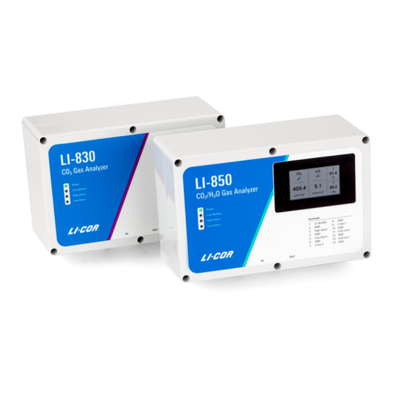
0 to 20,000 ppm. The instruments differ in that the LI-850 measures water vapor in air as well, and the LI-830 does not. As a consequence of the water vapor measurement, the LI-850 is able to measure CO concentrations with greater accuracy. -
Page 10: What's What
Section 1. General description What's what The LI-830 and LI-850 include a core set of components and each may include optional components. These are described below. Gas analyzer This is the gas analyzer in an enclosure. It may include an optional built-in pump and display. -
Page 11: Accessories Kit
Section 1. General description Accessories kit The instrument includes a standard accessories kit, which has accessories and some Accessories kit: Part Number 9980-065 replacement parts for your gas analyzer. The accessories kit includes the following components: Description Quantity Part Number Universal power supply;... -
Page 12: Connecting With The Analyzer
Install an air filter on the air-in port Caution: Always install an air filter on the input air before operating the LI-830 or LI-850. Failure to use a filter will cause contamination of the optical bench. - Page 13 Section 1. General description Power on the gas analyzer The LI-830 and LI-850 will turn on when power is supplied, so plug in the power cable to turn it on. If you use an alternative power supply, it must be able to source a minimum of 1.2 A at 12 VDC while the instrument warms up.
-
Page 14: The Terminal Strip
Ground V OUT 2 Voltage output channel 2 Ground V OUT 1 Voltage output channel 1 Ground 4-20 mA 2 Current output channel 2 Ground 4-20 mA 1 Current output channel 1 Ground Using the LI-830 and LI-850 Gas Analyzers... -
Page 15: Powering The Li-830 And Li-850
A power supply—either a battery or the universal power adapter—can be connected to the LI-830 and LI-850 power jack or to pins 1 and 2 on the terminal strip. The instruments require 12 to 30 VDC. The power supply must be able to provide 14 watts (1.2 A at 12 V) during warmup and about 3.6 watts (0.3 A at 12 V) during... -
Page 16: Installing Device Drivers
Installing device drivers If you are using Windows 7 and 8, you'll need to install device drivers. After con- necting the LI-830 or LI-850 to your computer with the USB cable, follow these steps: Download the drivers and unzip the file. -
Page 17: Section 2. Configuring The Gas Analyzer
Section 2. Configuring the gas analyzer This section describes the basic operating procedures for the LI-830 and LI-850 gas analyzers. This section depends upon the instrument software, which can be down- loaded from the LI-COR technical support web site: www.licor.com/env/support. Overview of the software After connecting, the software presents you with live data and graphs. -
Page 18: Configuring Graphs
When checked, you can choose from CO concentration, cell tem- perature, cell pressure, CO absorption, or input voltage. With the LI-850, the H concentration, H O dewpoint, and H O absorption will also be available. Using the LI-830 and LI-850 Gas Analyzers... -
Page 19: Logging Data To A Pc
Section 2. Configuring the gas analyzer Logging data to a PC The instrument can log data as a text file, which will be stored to the connected computer. Configure the log file under . To log data: Settings > Logging Options Create a file. -
Page 20: Instrument Settings
With the 0 to 5 volt output range corresponding with a 0 to 20,000 ppm CO con- centration range, the finest change in concentration that can be resolved is equal to 0.31 ppm. Using the LI-830 and LI-850 Gas Analyzers... -
Page 21: Computing Readings From The Dac Output
Section 2. Configuring the gas analyzer If you are measuring concentrations between 0 and 10,000 ppm, the range is 10,000 ppm. By configuring the DAC range for 0 V = 0 ppm CO and 5 V = 10,000 ppm, the DAC output will have twice the resolution as it would in the previous configuration. - Page 22 In this example, let's configure the output range so that 4 mA = 300 ppm and 20 mA = 500 ppm. Now, we need an offset that corresponds with the minimum CO reading (300 ppm). 2-10 If the current is 16.25 mA, then 2-11 Using the LI-830 and LI-850 Gas Analyzers...
-
Page 23: Other Options
Section 2. Configuring the gas analyzer Example 5: Computing cell temperature from a voltage output Cell temperature (T in °C) is calculated from the DAC output with the following: 2-12 where X is the full scale temperature value that corresponds to the high voltage, is the temperature value that corresponds to the low voltage, V is the voltage reading, and V is the output range (either 2.5 V or 5 V). -
Page 24: Using Alarms
700 ppm. The alarm is deactivated when the concentration drops below 600 ppm. Figure 2-3. The window is where you configure alarms. The settings shown Alarm Settings here will give the behavior shown in Figure 2-2 above. Using the LI-830 and LI-850 Gas Analyzers... - Page 25 Section 2. Configuring the gas analyzer (transistor-to-transistor logic), the instrument sends a +5 V signal TTL mode when the alarm is off and a 0 V signal when it is on. The alarm can be used to activate a relay switch or send a digital signal, for example. In Open collector mode the alarm works like a switch.
-
Page 26: Using The Pump
Section 2. Configuring the gas analyzer Using the Pump For instruments that are equipped with the LI-COR-installed pump, the pump is activated through the interface. Note: The pump will not run until the optical cell has reached the operating temperature of about 50 °C, regardless of the setting. If the cell temperature drops below 50 °C, the instrument will disable the pump temporarily until the... -
Page 27: Section 3. Troubleshooting
Section 3. Troubleshooting In this section, we describe how to identify some potential problems. If you can't find a solution here, contact your local distributor or LI-COR technical support for more help. Instrument will not power on Power supply adequate? The power supply should source at least 1.2 amps at 12 VDC (minimum of 14 watts during warmup). -
Page 28: Instrument Reports -50 Ppm Co2 Or Measurements Jump Around
If the instrument measures -50 ppm or the measurements are going between neg- ative and positive values, or just simply not making any sense, the optical source may have failed or be in the midst of failure. Contact technical support for addi- tional troubleshooting help. Using the LI-830 and LI-850 Gas Analyzers... -
Page 29: Section 4. Maintenance
Section 4. Maintenance The LI-830 and LI-850 will require little maintenance. Typical maintenance pro- cedures are described in this section. User calibration If the instrument is not measuring as expected, or if you have disassembled the optical bench for any reason, you should check the zero and span settings and set them if necessary. - Page 30 0.5 liters per minute. Flow Meter Rotameter × 100 cc/min Regulator Span Vent Enter the CO concentration of the span gas into the software When the CO reading has stabilized, click Span CO Using the LI-830 and LI-850 Gas Analyzers...
-
Page 31: Setting The Secondary Co2 Span
Section 4. Maintenance Setting the secondary CO span You can set a second span (using a gas that has a CO concentration that is higher or lower than the primary span gas) to improve the precision of the analyzer. The process is exactly the same as setting the primary span, only you'll enter a different concentration and click Span2 CO... -
Page 32: Cleaning The Optical Bench
Carefully lift the optical bench out of the foam. Remove the screws that secure the source and detector (4 each), then separate the source and detector housings (with circuit boards attached) from the optical path. Using the LI-830 and LI-850 Gas Analyzers... - Page 33 If the tubes are dirty or damaged, replace them with new tubes (available from LI-COR, part number 6580-041). Carefully remove them from the hose barbs. If the tubes are in good condition and clean, you may be able to reuse them. If the hose barbs are dirty, remove them and clean them with rubbing alcohol or soapy water.
-
Page 34: Replacing A Fuse
Using a needle-nose pliers, grasp the blown fuse and remove it from the holder. Replace it with a spare fuse. Power on the instrument to verify that the issue is resolved. Using the LI-830 and LI-850 Gas Analyzers... -
Page 35: Appendix A. Equation Summary
S( α ) is the span function, and raw absorptance α is computed from where V and V are the raw detector sample and reference readings, and Z is the zeroing parameter. Span is a linear function of absorptance. Using the LI-830 and LI-850 Gas Analyzers... - Page 36 O. This is measured at the factory and accounted for in the computation of absorptance (equation A-10). There is also a band broadening effect that is accoun- ted for in the computation of concentration (equation A-14). absorptance α c is computed from A-10 Using the LI-830 and LI-850 Gas Analyzers...
- Page 37 Appendix A. Equation Summary where V and V are the raw detector signals for sample and reference, Z is the zero parameter, and X is a cross sensitivity parameter for the effect of water vapor on CO . Its value is reported on the calibration sheet as The empirical pressure correction function g () depends on CO absorptance and...
- Page 38 ) and CO concentration is shown in Figure A-1 on the facing page. (‘Typical’ because the exact relationship depends on the rela- tionship between absorptance and CO , which is the calibration curve.) Using the LI-830 and LI-850 Gas Analyzers...
- Page 39 Appendix A. Equation Summary 1000 10000 100000 Approximate CO Concentration (ppm) Figure A-1. The typical relationship between h(α' ) and CO concentration. Note: We formulated equation A-19 with 0.64b – 0.64 instead of the simple equivalent (0.29) because this allows band broadening corrections to be turned =1, h( α...
- Page 40 A-24. Then, it uses these plus the retained values ( from the previous normal span) to compute A-26 Given the new span slope S , it updates the span offset S by equation A-23. Using the LI-830 and LI-850 Gas Analyzers...
- Page 41 Appendix A. Equation Summary Spanning CO When the command for setting the CO span is received, along with the target con- centration C , the instrument computes S from equation A-28, where are averaged for 5 seconds. A-27 A-28 where A-29 Note that A-30...
- Page 42 A-29. Then it uses these, plus the retained values ( α and β from the previous normal span) to compute A-34 Given the new span slope S , it updates the span offset S by equation A-28. Using the LI-830 and LI-850 Gas Analyzers...
-
Page 43: Appendix B. Specifications
Zero drift is the change with temperature at 0 concentration. Span drift is the residual error after re-zeroing following a temperature change. Total drift is the change with temperature without re-zeroing or re-spanning. Using the LI-830 and LI-850 Gas Analyzers... - Page 44 Storage temperature range: -20 to 60 °C Operating humidity range: 0 to 80% RH Nominal flow rate: 0.75 liters minute Power consumption: <0.75 W Expected life span: 8,000 hrs in standard conditions with a normal load Using the LI-830 and LI-850 Gas Analyzers...
- Page 45 Appendix B. Specifications Display specifications (optional) Dimensions: 6.7 cm corner-to-corner Resolution: 400 × 200 px; monochrome Power consumption: <200 µW Displayed variables: CO reading, H O reading (LI-850 only), optical bench tem- perature, and pressure. Specifications subject to change without prior notice. Dimensional drawings Appendix B.
- Page 46 The image below shows the pin assignments for the 9-pin RS-232 serial connector. Serial communication parameters The LI-830 and LI-850 can communicate through a RS-232 serial port on the front of the instrument. You may need to set the communication parameters on your computer or your terminal emulator program.
-
Page 47: Appendix C. Warranty
Inc.'s examination discloses to have been defective in material or workmanship without charge and only under the following conditions, which are: The defects are called to the attention of LI-COR, Inc. in Lincoln, Nebraska, in writing within one year after the shipping date of the instrument. - Page 48 The foregoing constitutes LI-COR, Inc.'s sole obligation and liability with respect to damages resulting from the use or performance of the instrument and in no event shall LI-COR, Inc. or its representatives be liable for damages beyond the price paid for the instrument, or for direct, incidental or con- sequential damages.
- Page 50 Regional Offices LI-COR Biosciences GmbH Siemensstraße 25A 61352 Bad Homburg Germany Phone: +49 (0) 6172 17 17 771 envsales-gmbh@licor.com LI-COR Biosciences UK Ltd. St. John’s Innovation Centre Cowley Road Cambridge CB4 0WS United Kingdom Phone: +44 (0) 1223 422102 envsales-UK@licor.com LI-COR Distributor Network: www.licor.com/env/distributors...
Need help?
Do you have a question about the LI-830 and is the answer not in the manual?
Questions and answers