
Subscribe to Our Youtube Channel
Related Manuals for Unical SPK 1000


Summary of Contents for Unical SPK 1000
- Page 1 18:28 giov 30 °C °C °C effettiva richiesta sanitaria 10/10 generatore modulazione status INFO MENU SPK 1000 INSTALLATION AND MAINTENANCE INSTRUCTIONS...
- Page 2 http://www.unicalag.it/catalogo-prodotti/professionale-300/334/commercial-condensazione-inox Provisions for proper disposal of the product After decommissioning, this appliance must not be disposed of as mixed urban waste. Separate waste collection is mandatory for this type of waste, in order to allow the recovery and reuse of the materials making up the appliance.
- Page 3 Attenzione il presente manuale contiene istruzioni ad uso esclusivo dell’installatore e/o del manutentore professionalmente qualificato, in conformità alle leggi vigenti. L’utente NoN è abilitato a intervenire sulla caldaia. Nel caso di danni a persone, animali o cose derivanti dalla mancata osservanza delle istruzioni contenute nei manuali forniti a corredo con la caldaia, il costruttore non può...
-
Page 4: General Information
Any product repairs must be performed solely by personnel The instruction booklet is an integral and essential part of the authorised by unical, using original spare parts only. failure to product and must be kept by the user. comply with the above can compromise the safety of the appli- ance and void the warranty. -
Page 5: Symbols Used In The Manual
Any other use must be considered improper. For any damage resulting from improper use, UNICAL AG S.p.A. assumes no responsibility. Use according to the intended purposes also includes strict compliance with the instructions in this manual. 1.4 - INFORMATION FOR THE SYSTEM MANAGER The user must be instructed concerning the use and operation of his heating system, in particular: •... -
Page 6: Safety Warnings
1.5 - SAFETY wARNINGS ATTENTION! The appliance must not be used by children. The appliance may be used by adults and only after carefully reading the operating instructions manual for the user. Children must be supervised so they do not play or tamper with the appliance. ATTENTION! The appliance must be installed, adjusted and maintained by professionally qualified personnel, in com- pliance with the standards and provisions in force. -
Page 7: Technical Data Plate
1.6 - TECHNICAL DATA PLATE KEY: CE marking 1 = CE monitoring body The CE marking certifies that the boilers meet: 2 = Type of boiler The essential requirements of the gas appliance directive 3 = Boiler model (directive 2009/142/EEC) 4 = Number of stars (directive 92/42 EEC) The essential requirements of the electromagnetic compat- 5 = (S.N°) Serial Number... -
Page 8: Water Treatment
1.7 - wATER TREATMENT ATTENTION! feed water treatment prevents problems and ANY DAMAGE TO THE BOILER CAUSED BY maintains the functionality and efficiency of the THE FORMATION OF FOULING OR BY COR- generator over time. ROSIVE wATER wILL NOT BE COVERED BY THE wARRANTY. -
Page 9: Boiler Antifreeze Protection
1.8 - BOILER ANTIFREEZE PROTECTION It is activated by default This protection can intervene only if the electricity and gas supplies are connected. If one of the two is not available and upon reset 11 (Sm) a temperature level between 2 and 5°C is detected, the appliance will behave as described in the table below, pos 2. -
Page 10: Technical Features And Dimensions
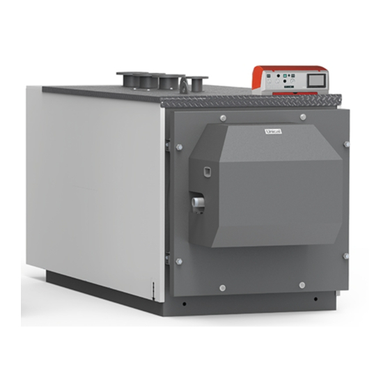
2.2 - MAIN COMPONENTS flow Low temperature return SPK 1000 boiler is equipped with a cylindrical furnace in whi- ch the flame of the premix burner develops towards the rear High temperature return door, where the first inversion of the fumes occurs in the pipes Expansion vessel of the second pass. - Page 11 Slides for sliding burner assembly outlet wiring (dx / sx) Detection electrode Gas Valve Burner Ignition electrode (n.2) Ignition transformer ( n.2)
-
Page 12: Front View
2.4 - DIMENSIONS SPK 1000 FRONT VIEw BACK VIEw 18:28 giov 30 °C °C °C effettiva richiesta sanitaria 10/10 generatore modulazione status INFO MENU UPPER VIEw Rat T3 M T1 Rbt T2 DImENSIoNS [mm] Chim- Depth Width Height Furnace Focolare... - Page 13 SIDE VIEw SECTION Rat T3 Rbt T2 M T1 SIDE VIEw wITH CASING CoNNECTIoNS Weight T1 (m) T2 (r) T3 (r) T5 (Sc) T7 (S) T8 (Scond) inch [mm] [mm] [mm] inch 1000 DN 125 DN 125 DN 125 DN 65 r 1’’...
-
Page 14: Types Of Gas
2.5 - OPERATING DATA AND GENERAL FEATURES for the adjustment data: NozzLES - PrESSurE - DIAGrAmS - fLoW rATES refer to the paragraph ADAPTATIoN To oTHEr TYPES of GAS. 1000 Boiler category modulation ratio rated heat output on P.C.I. Qn minimum heat output on P.C.I. - Page 15 2.5.1 - TECHNICAL DATA ACCORDING ErP DIRECTIVE 1000 Element Symbol Unit Effective nominal output Pnominale Seasonal energy efficiency to heat ƞ the room Season efficiency class to discharge For CH only and combination boilers: useful heat output useful Heat output in high-tempera- ture regime 923,2 (Tr 60 °C / Tm 80 °C)
-
Page 16: Installation Instructions
INSTALLATION INSTRUCTIONS ATTENTION! 3.1 - GENERAL wARNINGS If there is dust and/or if there are aggressive/corrosive vapours present in ATTENTION! the installation room, the appliance must This boiler is intended solely for the use for be protected suitably and must be able to which it was expressly designed. - Page 17 If it is possible to program replacements, you must provide NOTE! for intervention with protective washing equipped with basic Further details in the section dispersant. ‘‘Technical Information’’ on the boiler Washing must be carried out four weeks prior to replacement, page of the www.unicalag.it website with the system operating at 35°C - 40°C Attention! If the new boiler was replaced in an old system...
-
Page 18: Positioning In Boiler Room
3.5 - POSITIONING IN BOILER ROOM Comply with the minimum overall dimension The boiler must be installed in compliance with standards and distances in order to execute normal prescriptions in force. maintenance and cleaning operations. The room must be well ventilated by openings with a total surface no less than 1/30 the surface of the boiler room, with a minimum of 0.5 m². -
Page 19: Important Note
3.5.1 - IMPORTANT NOTE Before opening the hearth door, the following safety measures must be taken: ATTENTION - Cool the boiler by circulating the system water, and then Danger of burns! the flame control light can disconnect the burner from the electricity supply. Put a sign be very hot;... -
Page 20: Flue Gas Exhaust Pipe Connection
3.6 - FLUE GAS EXHAUST PIPE CONNECTION To connect the flue gas exhaust pipe, local and national stand- ards must be observed In the event the boiler is replaced, ALWAYS replace the flue gas pipe as well. The boiler is type approved for the exhaust configurations listed below: B23P ATTENTION... - Page 21 3.7 - CONNECTION CoNNECTIoNS M (T1) R (at / bt) (T2 - 3) return Gas Inlet flow expansion vessel Boiler drain flue gas Condensation drain [Inch] [PN6 - DN] [PN6 - DN] [PN6 - DN] [Inch] exhaust [Ø mm] [Ø mm] 1000 2’’...
-
Page 22: Condensate Drain
3.8 - CONDENSATE DRAIN Danger! The boiler, during the combustion process, produces conden- Before commissioning the appliance: sation that, through pipe “A”, flows into the trap. - check that the trap is assembled The condensation that forms inside the boiler flows into a suitable of the siphon (* H = XXX mm) drain via pipe “B”. -
Page 23: Filling And Emptying The System
3.9 - FILLING AND EMPTYING THE SYSTEM When all system connections have been com- pleted, the circuit can be filled. To fill the system, you must provide a filling valve on the system's return. EXAMPLE OF THE SYSTEM'S LOADING UNIT uNIT of LoADING... -
Page 24: Electrical Connections
3.9 - ELECTRICAL CONNECTIONS Danger! Only a qualified technician may perform trical parts, always disconnect electrical power and make the electrical installation. Before performing sure that it cannot be reconnected accidentally. connections or any type of operation on elec- 3.9.1 - PANEL BOARD 6.3 Af 6.3 Af N°... - Page 25 3.9.2 - BOILER POWER SUPPLY (*) The Dashed links and BOX general electrical by installer. ALIM. 400 V 50 Hz off 6.3 A Power supply connection 400V The installation of the boiler requires the electrical connection to a 400 V - 50 Hz network and a 230V - 50 Hz connection: these L1 PE N connections must be made as required by current standards.
- Page 26 NOTE: fan terminal block connection The dotted links are edited of the installer 0-10V NC COM Tach NOTE: TA connection (*) View of the internal panel position of the BCM board and 24 V terminal block for connections. ON-OFF 12 11 10 9 8 7 6 5 4 3 2 1 +24V 3 4 5 6 7 10 11 12 13 14...
- Page 27 INAIL safety connections FL Flow switch connection (*) Safety connection 12 11 10 9 8 7 6 5 4 3 2 1 12 11 10 9 8 7 6 5 4 3 2 1 +24V +24V 3 4 5 6 3 4 5 6 7 - remove the jumper and connect the cables as indicated - remove the jumper and connect the cables as indicated...
- Page 28 tanks, mixed areas, solar, etc), you must purchase SHC multi- NOTE: function modules to connect to the local bus for total manage- The boiler is set up for direct flow and storage tank ment through HSCP (and UFLY) heating controller. management.
- Page 29 3.10 - COMMISSIONING Commissioning must be done by professionally Before commissioning the boiler, check that: qualified personnel. The manufacturer will not be held liable for damage to persons, animals or objects due to failure to comply with the aforesaid instructions. does the installation meet the specific standards and regulations in force, both relating to the gas part as well as the electrical part? do the combustion air intake and flue gas exhaust take place properly according to...
-
Page 30: Positioning The Probes
3.11 - MEASUREMENT OF THE COMBUSTION EFFICIENCY DURING INSTALLATION Generator Menu 3.11.1 - CALIBRATION FUNCTION (CHIMNEY SwEEP) ATTENTION! ATTENTION! These functions are explained in Function reserved for After Sale chapter 6 (Burner menu) of the Service Centres only. Ufly P. installation and mainte- nance manual. - Page 31 GAS VALVE 1) Minimum output adjustment 2) Maximum output adjustment - operate the boiler in “calibration” mode at mINImum ouTPuT - operate the boiler in “calibration” mode at mAXImum ouT- (see 3.11.1) PuT (see 3.11.1) - once the burner is on, check that the “mINImum” Co2 output - once the burner is on check value corresponds to what is indicated in the table “NozzLES that the “mAXImum”...
- Page 32 If the capacity read is too low, make sure the power exchanger is not dirty. supply system and drain (power supply and drain pipes) are not clogged. NOZZLES - PRESSURE - FLOw RATES TABLE SPK 1000 Type of Gas Supply Press. Ø Noz- opening...
-
Page 33: Inspection And Maintenance Instructions
INSPECTION AND MAINTENANCE Yearly maintenance of the appliance is mandatory ATTENTION in compliance with Laws in force. before opening the combustion chamber, failure to perform Inspections and maintenance cool the fibre. can entail material and personal damage Inspections and maintenance performed profes- sionally and according to a regular schedule, as OBLIGATION! well as the use of original spare parts, are of the... - Page 34 ROUTINE YEARLY VERIFICATION OPERATIONS COMPONENT: VERIFY: CONTROL/INTERVENTION METH- Does the valve modulate properly? The check is carried out in “Calibration” (Gas valve) mode, requesting 100% , 50%, and minimum modulation percentage. Check the modules flame. SR (flow sensor) ( Do the sensors maintain the 12571 ohm at 20°...
-
Page 36: Programming The Operating Parameters
3.15 - PROGRAMMING THE OPERATING PARAMETERS ATTENTION! ATTENTION! These functions are explained Function reserved for After Sale in chapter chapter 8 (Device Service Centres only. setting) of the Ufly P installation and maintenance manual. Bmm parameters Simb Description unit min. max. - Page 37 BCm Parameters Code Symbol Description unit min. max. Imp. fab. Enabled Services Gen: Temp. Max Differential °K 50,0 Burner Hysteresis °K 20,0 CH#1: minimum Set-point °C 20,0 40.0 CH#1: maximum Set-point °C 45,0 85.0 Input 0/10V Programmable Input #1 Pump: Post-circulation min.
- Page 38 4.5 - PRACTICAL CONNECTION wIRING DIAGRAM ALIM. 400 V 50 Hz off 6.3 A L1 PE N Ufly / HSCP Ufly P ROD1 ROD 4 5 6 U-FLY TEFLON WH E.RIL. PF min Minimum flue pressure pressure switch (NO WKVV 1000 A1..A Services connectors PG max Gas maximum pressure switch E. ACC. 1-2 Ignition electrode 1-2 PG min...
- Page 39 INAIL 12 11 10 9 8 7 6 5 4 3 2 1 +24V 1000) 3 4 5 6 7 10 11 12 13 14 1 2 3 4 5 6 + 20/40Vdc - 20/40Vdc eBUS+ 3 4 5 6 7 10 11 12 13 14 ROD1 ROD 4 5 6...
-
Page 40: Error Codes
4.6 - ERROR CODES fault that causes the Hot water Generator to stop: fault that does NoT cause the Hot water Generator to stop: - The error code is displayed, the Hot water Generator has stopped running. After solving the - The error code is displayed, the Hot water failure, press reset to restart the Hot water Generator has a heating request, reset icon (in-... - Page 41 UNATTENDED AIR FLOw min pressure switch blocked (closed) SPEED OUT OF CONTROL Check fan operation and the connections Alteration of the fan speed; the speed is not reached. SPEED OUT OF CONTROL Check fan operation and the connections Alteration of the fan speed; the speed is above that requested Verify that the fan has a prevalence of at least 60 Pa.
- Page 44 S.p.A. info@unical-ag.com - export@unical-ag.com - www.unical.eu unical shall not be held liable for any inaccuracies due to transcription or printing errors. Furthermore, it reserves the right to modify its products as deemed necessary or useful, without affecting their essential features.
Need help?
Do you have a question about the SPK 1000 and is the answer not in the manual?
Questions and answers